Page 130 of 172

LT-130
INTERIOR ROOM LAMP
Revision: 2006 November2007 350Z
When the driver side door is unlocked by door key cylinder switch, The BCM receives information by commu-
nicating with power window main switch
�through grounds M30 and M66
�to door key cylinder switch terminal 2
�through door key cylinder switch terminal 1
�to power window main (door lock and unlock switch) switch terminal 7
�through power window main switch (door lock and unlock switch) terminal 12
�to BCM terminal 22.
When a signal, or combination of signals is received by BCM, ground is supplied
�through BCM terminal 48
�to map lamp terminal 2 (Coupe models)
�to map lamp terminal 3 (Roadster models).
With power and ground are supplied, map lamp illuminates.
SWITCH OPERATION
When map lamp switch is ON, ground is supplied
�to map lamp terminal 1 (Coupe models)
�to map lamp terminal 1 (Roadster models)
�through grounds M30 and M66.
And power is supplied
�through BCM terminal 41
�to ignition key hole illumination terminal 1
�to map lamp terminal 3 (Coupe models)
�to map lamp terminal 2 (Roadster models).
When vanity mirror lamp LH and RH is ON, ground is supplied
�to vanity mirror lamp LH and RH terminals 2
�through grounds M30 and M66.
And power is supplied
�through BCM terminal 41
�to vanity mirror lamp terminal 1.
MAP LAMP TIMER OPERATION
When the map lamp switch is in the DOOR position, and when all conditions below are met, BCM performs
timer control (maximum 30 seconds) for map lamp ON/OFF.
In addition, when map lamp turns ON or OFF there is gradual brightening or dimming over 1 second.
Power is supplied at all times
�to 10A fuse [No. 21 located in fuse block (J/B)]
�through key switch terminal 2.
When all doors are closed (all door switches OFF) and key is removed from key cylinder (key switch OFF),
power will not be supplied to BCM terminal 37.
Ground is supplied
�through BCM terminal 22
�to power window main switch (door lock and unlock switch) terminal 12.
At this time, BCM detects that driver door is unlocked. It determines that map lamp timer operation conditions
are met, and turns map lamp ON for 30 seconds.
When all doors are closed (all door switches OFF) and key is in key cylinder (key switch ON),
Power is supplied
�through key switch terminal 1
�to BCM terminal 37.
When the key is removed from key switch (key switch OFF), power supply to BCM terminal 37 is terminated.
BCM detects that key has been removed. It determines that map lamp timer conditions are met, and turns
map lamp ON for 30 seconds.
Page 131 of 172

INTERIOR ROOM LAMP
LT-131
C
D
E
F
G
H
I
J
L
MA
B
LT
Revision: 2006 November2007 350Z
When driver door opens → closes, and key is not inserted in key switch (key switch OFF), BCM terminal 62
changes between 0V (door open) → 5V (door closed). BCM determines that conditions for spot lamp opera-
tion are met and turns interior lamp ON for 30 seconds.
Timer control is canceled under the following conditions.
�Driver door is locked (When locked key fob or power window main switch (door lock and unlock switch,
door key cylinder switch).
�Driver door is opened (driver door switch turns ON).
�Ignition switch ON.
INTERIOR LAMP BATTERY SAVER CONTROL
If the room lamp remains illuminated by door switch open signal, or if room lamp switch is in the ON position
for more than 30 minutes after the ignition switch is turned to the OFF position, BCM will automatically turn off
map lamp, luggage room lamp (Coupe models), trunk room lamp (Roadster models) and vanity mirror lamp.
After lamps turn OFF by battery saver system, the lamps illuminate again when
�signal from key fob, door lock and unlock switch, or key cylinder is locked or unlocked,
�door is opened or closed,
�key is removed from ignition key cylinder or inserted in ignition key cylinder.
Interior lamp battery saver control period can be changed by the function setting of CONSULT-III.
Page 141 of 172

INTERIOR ROOM LAMP
LT-141
C
D
E
F
G
H
I
J
L
MA
B
LT
Revision: 2006 November2007 350Z
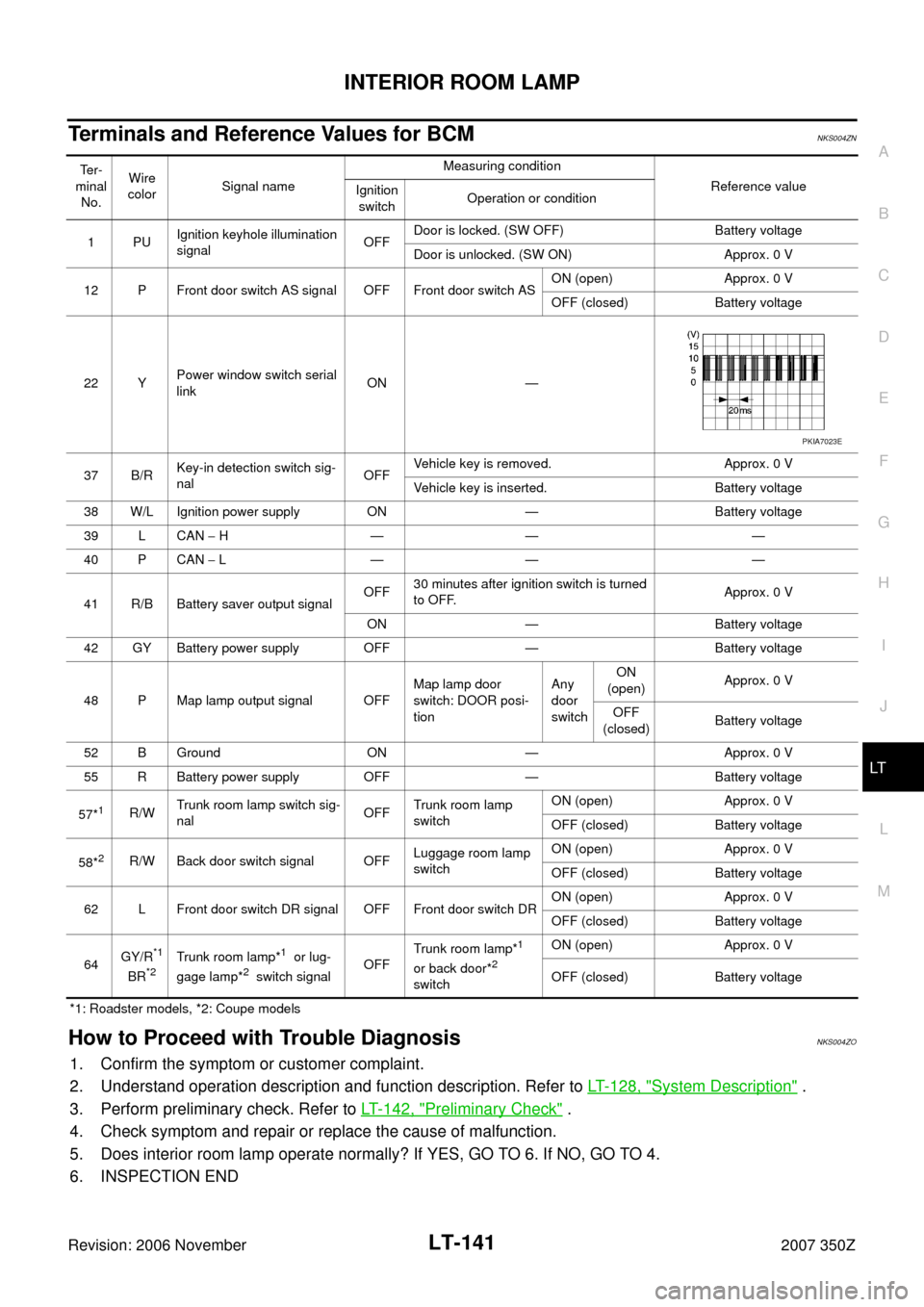
Terminals and Reference Values for BCMNKS004ZN
*1: Roadster models, *2: Coupe models
How to Proceed with Trouble DiagnosisNKS004ZO
1. Confirm the symptom or customer complaint.
2. Understand operation description and function description. Refer to LT- 1 2 8 , "
System Description" .
3. Perform preliminary check. Refer to LT- 1 4 2 , "
Preliminary Check" .
4. Check symptom and repair or replace the cause of malfunction.
5. Does interior room lamp operate normally? If YES, GO TO 6. If NO, GO TO 4.
6. INSPECTION END
Te r -
minal
No.Wire
colorSignal nameMeasuring condition
Reference value
Ignition
switchOperation or condition
1PUIgnition keyhole illumination
signalOFFDoor is locked. (SW OFF) Battery voltage
Door is unlocked. (SW ON) Approx. 0 V
12 P Front door switch AS signal OFF Front door switch ASON (open) Approx. 0 V
OFF (closed) Battery voltage
22 YPower window switch serial
linkON —
37 B/RKey-in detection switch sig-
nalOFFVehicle key is removed. Approx. 0 V
Vehicle key is inserted. Battery voltage
38 W/L Ignition power supply ON — Battery voltage
39 L CAN − H—— —
40 P CAN − L—— —
41 R/B Battery saver output signalOFF30 minutes after ignition switch is turned
to OFF.Approx. 0 V
ON — Battery voltage
42 GY Battery power supply OFF — Battery voltage
48 P Map lamp output signal OFFMap lamp door
switch: DOOR posi-
tionAny
door
switchON
(open)Approx. 0 V
OFF
(closed)Battery voltage
52 B Ground ON — Approx. 0 V
55 R Battery power supply OFF — Battery voltage
57*
1R/WTrunk room lamp switch sig-
nalOFFTrunk room lamp
switchON (open) Approx. 0 V
OFF (closed) Battery voltage
58*
2R/W Back door switch signal OFFLuggage room lamp
switch ON (open) Approx. 0 V
OFF (closed) Battery voltage
62 L Front door switch DR signal OFF Front door switch DRON (open) Approx. 0 V
OFF (closed) Battery voltage
64GY/R
*1
BR*2Trunk room lamp*1 or lug-
gage lamp*2 switch signalOFFTrunk room lamp*
1
or back door*2
switchON (open) Approx. 0 V
OFF (closed) Battery voltage
PKIA7023E
Page 153 of 172

INTERIOR ROOM LAMP
LT-153
C
D
E
F
G
H
I
J
L
MA
B
LT
Revision: 2006 November2007 350Z
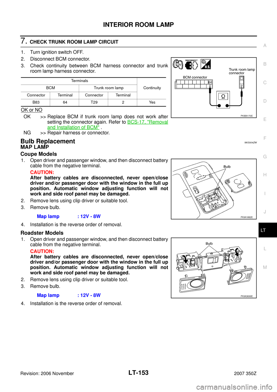
7. CHECK TRUNK ROOM LAMP CIRCUIT
1. Turn ignition switch OFF.
2. Disconnect BCM connector.
3. Check continuity between BCM harness connector and trunk
room lamp harness connector.
OK or NO
OK >> Replace BCM if trunk room lamp does not work after
setting the connector again. Refer to BCS-17, "
Removal
and Installation of BCM" .
NG >> Repair harness or connector.
Bulb ReplacementNKS004ZW
MAP LAMP
Coupe Models
1. Open driver and passenger window, and then disconnect battery
cable from the negative terminal.
CAUTION:
After battery cables are disconnected, never open/close
driver and/or passenger door with the window in the full up
position. Automatic window adjusting function will not
work and side roof panel may be damaged.
2. Remove lens using clip driver or suitable tool.
3. Remove bulb.
4. Installation is the reverse order of removal.
Roadster Models
1. Open driver and passenger window, and then disconnect battery
cable from the negative terminal.
CAUTION:
After battery cables are disconnected, never open/close
driver and/or passenger door with the window in the full up
position. Automatic window adjusting function will not
work and side roof panel may be damaged.
2. Remove lens using clip driver or suitable tool.
3. Remove bulb.
4. Installation is the reverse order of removal.
Terminals
Continuity BCM Trunk room lamp
Connector Terminal Connector Terminal
B83 64 T29 2 Yes
PKIB5170E
Map lamp : 12V - 8WPKIA1882E
Map lamp : 12V - 8WPKIA3699E