Page 41 of 82
POWER WINDOW SYSTEM
GW-41
C
D
E
F
G
H
J
K
L
MA
B
GW
Revision: 2006 November2007 350Z
5. CHECK ENCODER SIGNAL
1. Connect passenger side power window motor connector.
2. Turn ignition ON.
3. Check signal between power window sub-switch connector and ground with oscilloscope.
OK or NG
OK >> Replace power window sub-switch.
NG >> GO TO 6.
6. CHECK ENCODER CIRCUIT
1. Turn ignition switch OFF.
2. Disconnect power window sub-switch and passenger side power window motor connector.
3. Check continuity between power window sub-switch connector
D37 terminal 12 and passenger side power window motor con-
nector D38 terminal 3.
OK or NG
OK >> Replace passenger side power window motor.
NG >> Repair or replace harness.
ConnectorTerminals (Wire color)
ConditionSignal
(Reference valve)
(+) (-)
D37 12 (PU) Ground DOWN
PIIA2463EOCC3383D
12 (PU) – 3 (PU) : Continuity should exist.
PIIA8991E
Page 42 of 82
GW-42
POWER WINDOW SYSTEM
Revision: 2006 November2007 350Z
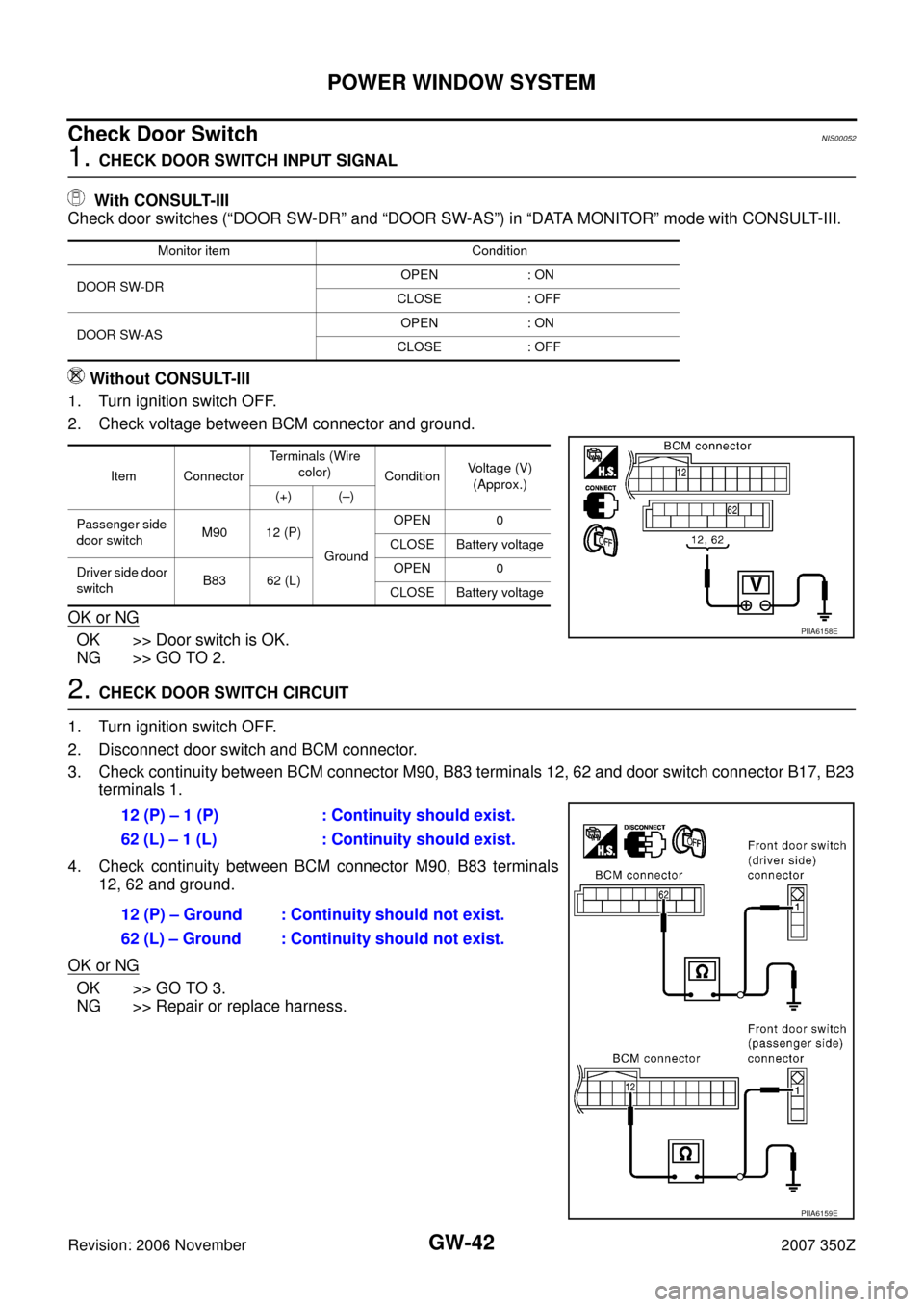
Check Door SwitchNIS00052
1. CHECK DOOR SWITCH INPUT SIGNAL
With CONSULT-III
Check door switches (“DOOR SW-DR” and “DOOR SW-AS”) in “DATA MONITOR” mode with CONSULT-III.
Without CONSULT-III
1. Turn ignition switch OFF.
2. Check voltage between BCM connector and ground.
OK or NG
OK >> Door switch is OK.
NG >> GO TO 2.
2. CHECK DOOR SWITCH CIRCUIT
1. Turn ignition switch OFF.
2. Disconnect door switch and BCM connector.
3. Check continuity between BCM connector M90, B83 terminals 12, 62 and door switch connector B17, B23
terminals 1.
4. Check continuity between BCM connector M90, B83 terminals
12, 62 and ground.
OK or NG
OK >> GO TO 3.
NG >> Repair or replace harness.
Monitor item Condition
DOOR SW-DROPEN : ON
CLOSE : OFF
DOOR SW-ASOPEN : ON
CLOSE : OFF
Item ConnectorTerminals (Wire
color)
ConditionVoltage (V)
(Approx.)
(+) (–)
Passenger side
door switch M90 12 (P)
GroundOPEN 0
CLOSE Battery voltage
Driver side door
switchB83 62 (L)OPEN 0
CLOSE Battery voltage
PIIA6158E
12 (P) – 1 (P) : Continuity should exist.
62 (L) – 1 (L) : Continuity should exist.
12 (P) – Ground : Continuity should not exist.
62 (L) – Ground : Continuity should not exist.
PIIA6159E
Page 47 of 82
POWER WINDOW SYSTEM
GW-47
C
D
E
F
G
H
J
K
L
MA
B
GW
Revision: 2006 November2007 350Z
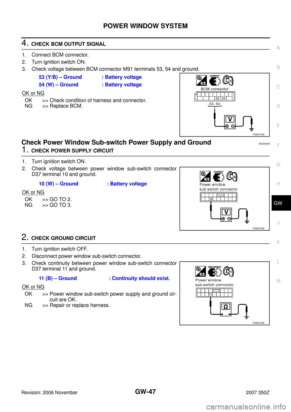
4. CHECK BCM OUTPUT SIGNAL
1. Connect BCM connector.
2. Turn ignition switch ON.
3. Check voltage between BCM connector M91 terminals 53, 54 and ground.
OK or NG
OK >> Check condition of harness and connector.
NG >> Replace BCM.
Check Power Window Sub-switch Power Supply and GroundNIS00055
1. CHECK POWER SUPPLY CIRCUIT
1. Turn ignition switch ON.
2. Check voltage between power window sub-switch connector
D37 terminal 10 and ground.
OK or NG
OK >> GO TO 2.
NG >> GO TO 3.
2. CHECK GROUND CIRCUIT
1. Turn ignition switch OFF.
2. Disconnect power window sub-switch connector.
3. Check continuity between power window sub-switch connector
D37 terminal 11 and ground.
OK or NG
OK >> Power window sub-switch power supply and ground cir-
cuit are OK.
NG >> Repair or replace harness.53 (Y/B) – Ground : Battery voltage
54 (W) – Ground : Battery voltage
PIIA6154E
10 (W) – Ground : Battery voltage
PIIA2754E
11 (B) – Ground : Continuity should exist.
PIIA2755E
Page 48 of 82
GW-48
POWER WINDOW SYSTEM
Revision: 2006 November2007 350Z
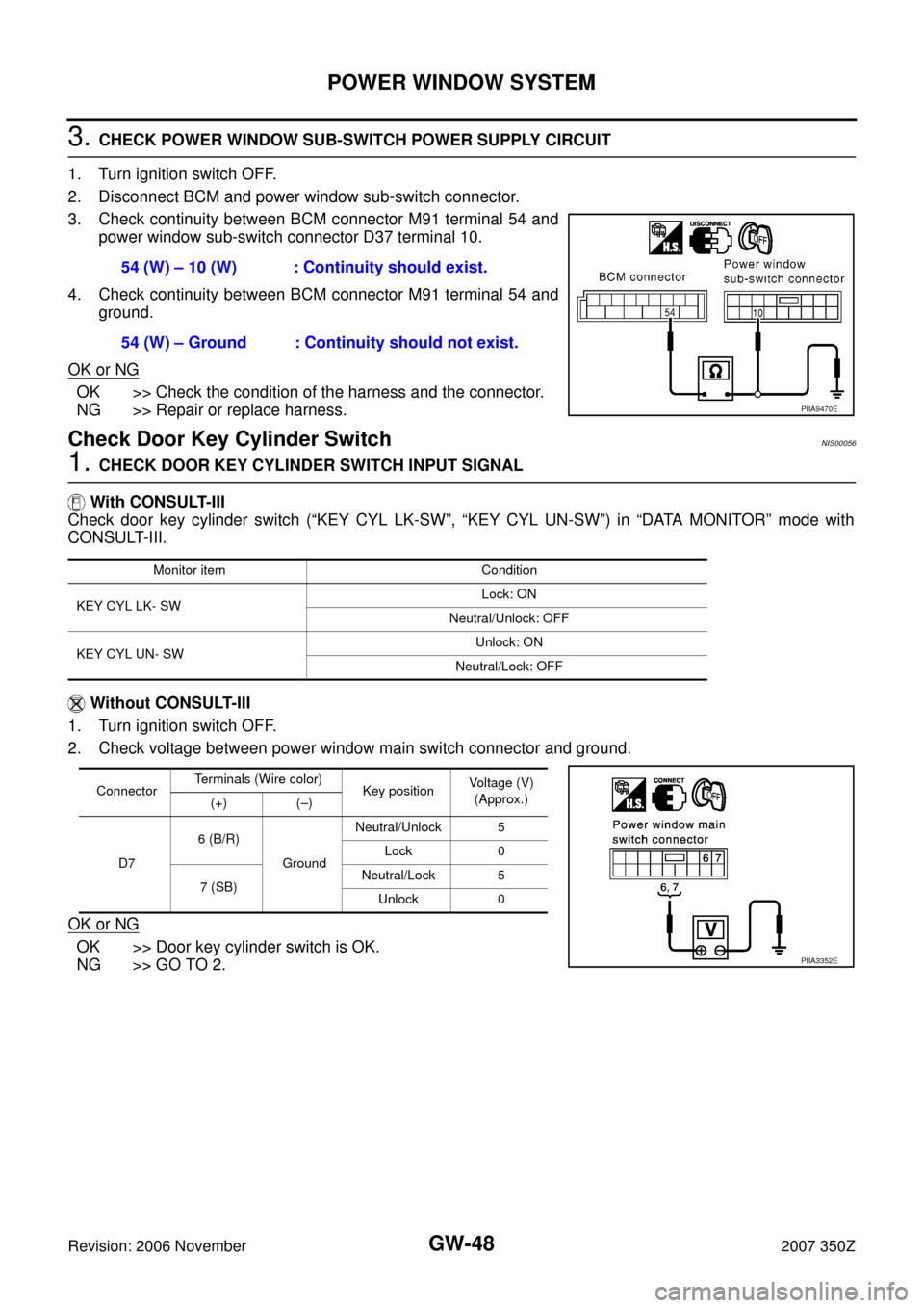
3. CHECK POWER WINDOW SUB-SWITCH POWER SUPPLY CIRCUIT
1. Turn ignition switch OFF.
2. Disconnect BCM and power window sub-switch connector.
3. Check continuity between BCM connector M91 terminal 54 and
power window sub-switch connector D37 terminal 10.
4. Check continuity between BCM connector M91 terminal 54 and
ground.
OK or NG
OK >> Check the condition of the harness and the connector.
NG >> Repair or replace harness.
Check Door Key Cylinder Switch NIS00056
1. CHECK DOOR KEY CYLINDER SWITCH INPUT SIGNAL
With CONSULT-III
Check door key cylinder switch (“KEY CYL LK-SW”, “KEY CYL UN-SW”) in “DATA MONITOR” mode with
CONSULT-III.
Without CONSULT-III
1. Turn ignition switch OFF.
2. Check voltage between power window main switch connector and ground.
OK or NG
OK >> Door key cylinder switch is OK.
NG >> GO TO 2.54 (W) – 10 (W) : Continuity should exist.
54 (W) – Ground : Continuity should not exist.
PIIA9470E
Monitor item Condition
KEY CYL LK- SWLock: ON
Neutral/Unlock: OFF
KEY CYL UN- SWUnlock: ON
Neutral/Lock: OFF
ConnectorTerminals (Wire color)
Key position Voltage (V)
(Approx.)
(+) (–)
D76 (B/R)
GroundNeutral/Unlock 5
Lock 0
7 (SB)Neutral/Lock 5
Unlock 0
PIIA3352E
Page 70 of 82
GW-70
REAR WINDOW DEFOGGER
Revision: 2006 November2007 350Z
Check IPDM E/R OperationNIS0005R
1. CHECK IPDM E/R OPERATION
With CONSULT-III
Check IPDM E/R “REAR DEFOGGER” in “ACTIVE TEST” mode with CONSULT-III.
Refer to GW-68, "
ACTIVE TEST" .
YES or NO
YES >> GO TO diagnosis/service procedure 3 in “Trouble Diagnosis Symptom Chart”. Refer to GW-69 .
NO >> GO TO diagnosis/service procedure 4 in “Trouble Diagnosis Symptom Chart”. Refer to GW-69
.
Check Rear Window Defogger Switch CircuitNIS0005S
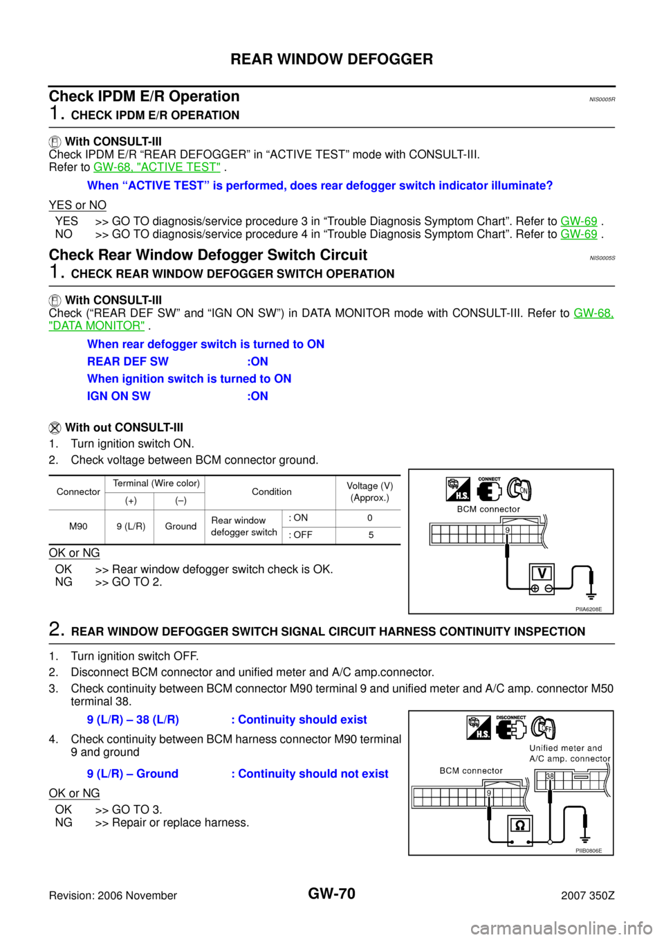
1. CHECK REAR WINDOW DEFOGGER SWITCH OPERATION
With CONSULT-III
Check (“REAR DEF SW” and “IGN ON SW”) in DATA MONITOR mode with CONSULT-III. Refer to GW-68,
"DATA MONITOR" .
With out CONSULT-III
1. Turn ignition switch ON.
2. Check voltage between BCM connector ground.
OK or NG
OK >> Rear window defogger switch check is OK.
NG >> GO TO 2.
2. REAR WINDOW DEFOGGER SWITCH SIGNAL CIRCUIT HARNESS CONTINUITY INSPECTION
1. Turn ignition switch OFF.
2. Disconnect BCM connector and unified meter and A/C amp.connector.
3. Check continuity between BCM connector M90 terminal 9 and unified meter and A/C amp. connector M50
terminal 38.
4. Check continuity between BCM harness connector M90 terminal
9 and ground
OK or NG
OK >> GO TO 3.
NG >> Repair or replace harness.When “ACTIVE TEST” is performed, does rear defogger switch indicator illuminate?
When rear defogger switch is turned to ON
REAR DEF SW :ON
When ignition switch is turned to ON
IGN ON SW :ON
ConnectorTerminal (Wire color)
ConditionVoltage (V)
(Approx.)
(+) (–)
M90 9 (L/R) GroundRear window
defogger switch: ON 0
: OFF 5
PIIA6208E
9 (L/R) – 38 (L/R) : Continuity should exist
9 (L/R) – Ground : Continuity should not exist
PIIB0806E
Page 72 of 82
GW-72
REAR WINDOW DEFOGGER
Revision: 2006 November2007 350Z
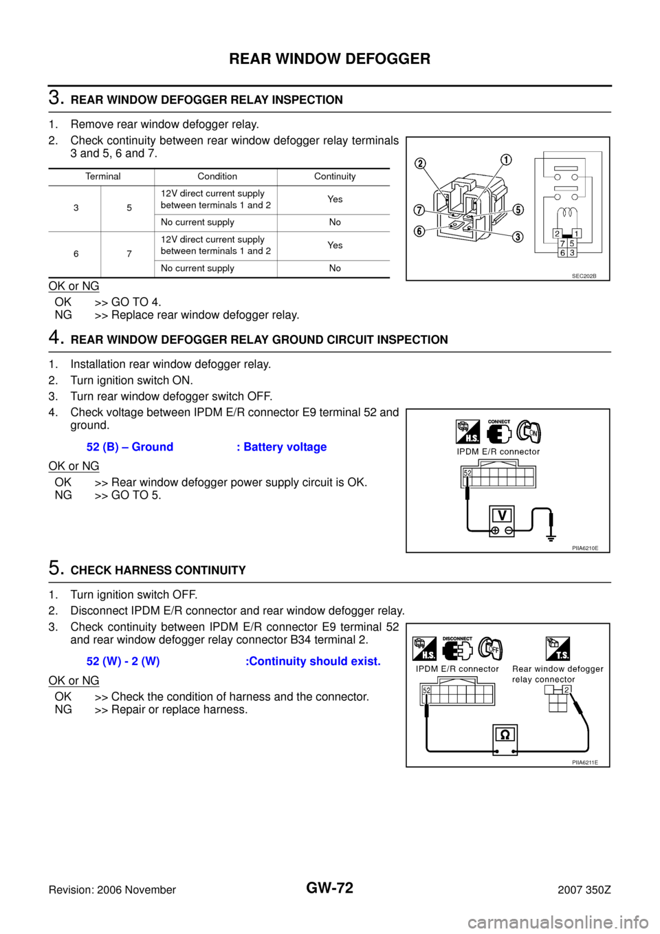
3. REAR WINDOW DEFOGGER RELAY INSPECTION
1. Remove rear window defogger relay.
2. Check continuity between rear window defogger relay terminals
3 and 5, 6 and 7.
OK or NG
OK >> GO TO 4.
NG >> Replace rear window defogger relay.
4. REAR WINDOW DEFOGGER RELAY GROUND CIRCUIT INSPECTION
1. Installation rear window defogger relay.
2. Turn ignition switch ON.
3. Turn rear window defogger switch OFF.
4. Check voltage between IPDM E/R connector E9 terminal 52 and
ground.
OK or NG
OK >> Rear window defogger power supply circuit is OK.
NG >> GO TO 5.
5. CHECK HARNESS CONTINUITY
1. Turn ignition switch OFF.
2. Disconnect IPDM E/R connector and rear window defogger relay.
3. Check continuity between IPDM E/R connector E9 terminal 52
and rear window defogger relay connector B34 terminal 2.
OK or NG
OK >> Check the condition of harness and the connector.
NG >> Repair or replace harness.
Terminal Condition Continuity
3512V direct current supply
between terminals 1 and 2Ye s
No current supply No
6712V direct current supply
between terminals 1 and 2Ye s
No current supply No
SEC202B
52 (B) – Ground : Battery voltage
PIIA6210E
52 (W) - 2 (W) :Continuity should exist.
PIIA6211E
Page 73 of 82
REAR WINDOW DEFOGGER
GW-73
C
D
E
F
G
H
J
K
L
MA
B
GW
Revision: 2006 November2007 350Z
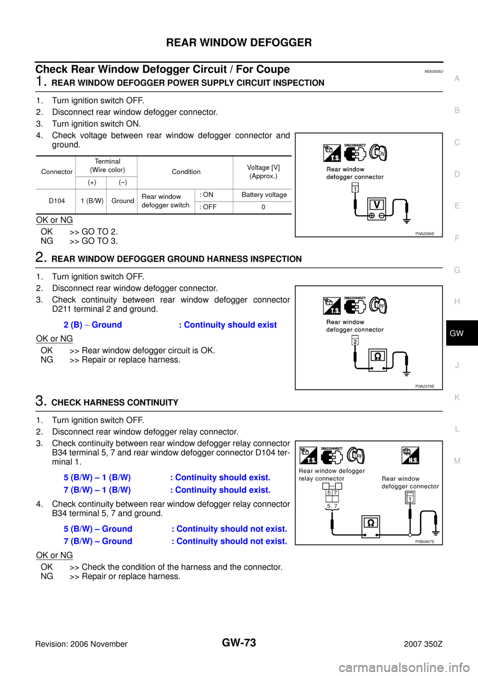
Check Rear Window Defogger Circuit / For CoupeNIS0005U
1. REAR WINDOW DEFOGGER POWER SUPPLY CIRCUIT INSPECTION
1. Turn ignition switch OFF.
2. Disconnect rear window defogger connector.
3. Turn ignition switch ON.
4. Check voltage between rear window defogger connector and
ground.
OK or NG
OK >> GO TO 2.
NG >> GO TO 3.
2. REAR WINDOW DEFOGGER GROUND HARNESS INSPECTION
1. Turn ignition switch OFF.
2. Disconnect rear window defogger connector.
3. Check continuity between rear window defogger connector
D211 terminal 2 and ground.
OK or NG
OK >> Rear window defogger circuit is OK.
NG >> Repair or replace harness.
3. CHECK HARNESS CONTINUITY
1. Turn ignition switch OFF.
2. Disconnect rear window defogger relay connector.
3. Check continuity between rear window defogger relay connector
B34 terminal 5, 7 and rear window defogger connector D104 ter-
minal 1.
4. Check continuity between rear window defogger relay connector
B34 terminal 5, 7 and ground.
OK or NG
OK >> Check the condition of the harness and the connector.
NG >> Repair or replace harness.
ConnectorTe r m i n a l
(Wire color)
ConditionVoltage [V]
(Approx.)
(+) (–)
D104 1 (B/W) GroundRear window
defogger switch: ON Battery voltage
: OFF 0
PIIA2396E
2 (B) − Ground : Continuity should exist
PIIA2378E
5 (B/W) – 1 (B/W) : Continuity should exist.
7 (B/W) – 1 (B/W) : Continuity should exist.
5 (B/W) – Ground : Continuity should not exist.
7 (B/W) – Ground : Continuity should not exist.
PIIB0807E
Page 74 of 82
GW-74
REAR WINDOW DEFOGGER
Revision: 2006 November2007 350Z
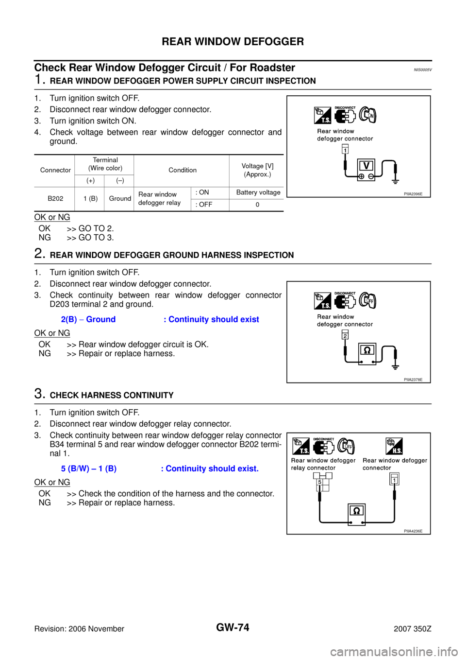
Check Rear Window Defogger Circuit / For RoadsterNIS0005V
1. REAR WINDOW DEFOGGER POWER SUPPLY CIRCUIT INSPECTION
1. Turn ignition switch OFF.
2. Disconnect rear window defogger connector.
3. Turn ignition switch ON.
4. Check voltage between rear window defogger connector and
ground.
OK or NG
OK >> GO TO 2.
NG >> GO TO 3.
2. REAR WINDOW DEFOGGER GROUND HARNESS INSPECTION
1. Turn ignition switch OFF.
2. Disconnect rear window defogger connector.
3. Check continuity between rear window defogger connector
D203 terminal 2 and ground.
OK or NG
OK >> Rear window defogger circuit is OK.
NG >> Repair or replace harness.
3. CHECK HARNESS CONTINUITY
1. Turn ignition switch OFF.
2. Disconnect rear window defogger relay connector.
3. Check continuity between rear window defogger relay connector
B34 terminal 5 and rear window defogger connector B202 termi-
nal 1.
OK or NG
OK >> Check the condition of the harness and the connector.
NG >> Repair or replace harness.
ConnectorTerminal
(Wire color)
ConditionVoltage [V]
(Approx.)
(+) (–)
B202 1 (B) GroundRear window
defogger relay: ON Battery voltage
: OFF 0
PIIA2396E
2(B) − Ground : Continuity should exist
PIIA2378E
5 (B/W) – 1 (B) : Continuity should exist.
PIIA4236E