Page 33 of 54

SERVICE INFORMATION FOR ELECTRICAL INCIDENT
GI-33
C
D
E
F
G
H
I
J
K
L
MB
GI
Revision: 2006 November2007 350Z
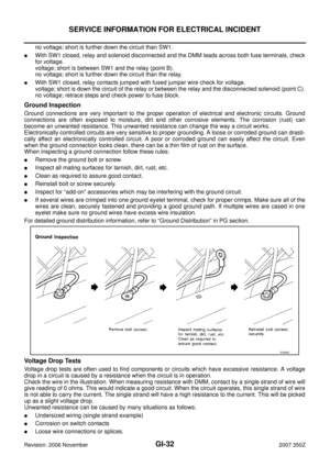
If repairs are needed always use wire that is of the same or larger gauge.
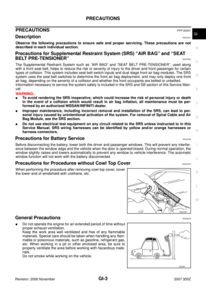
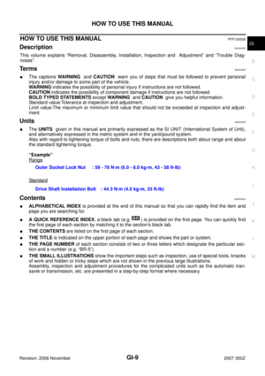
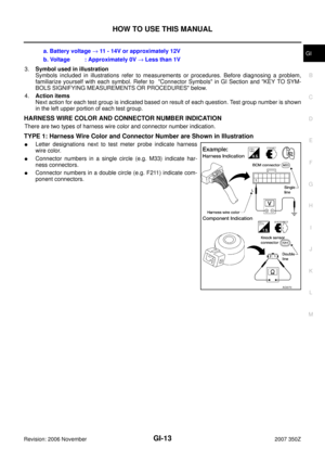
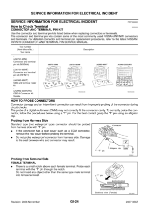
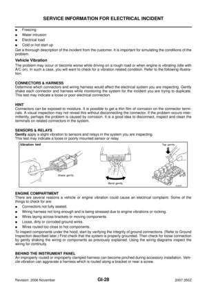
MEASURING VOLTAGE DROP — ACCUMULATED METHOD
�Connect the DMM across the connector or part of the circuit you want to check. The positive lead of the
DMM should be closer to power and the negative lead closer to ground.
�Operate the circuit.
�The DMM will indicate how many volts are being used to “push” current through that part of the circuit.
Note in the illustration that there is an excessive 4.1 volt drop between the battery and the bulb.
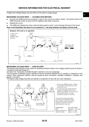
MEASURING VOLTAGE DROP — STEP-BY-STEP
The step-by-step method is most useful for isolating excessive drops in low voltage systems (such as those in
“Computer Controlled Systems”).
Circuits in the “Computer Controlled System” operate on very low amperage.
The (Computer Controlled) system operations can be adversely affected by any variation in resistance in the
system. Such resistance variation may be caused by poor connection, improper installation, improper wire
gauge or corrosion.
The step by step voltage drop test can identify a component or wire with too much resistance.
SGI974
SAIA0258E
Page 34 of 54

GI-34
SERVICE INFORMATION FOR ELECTRICAL INCIDENT
Revision: 2006 November2007 350Z
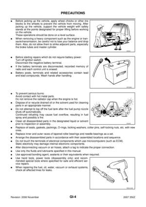
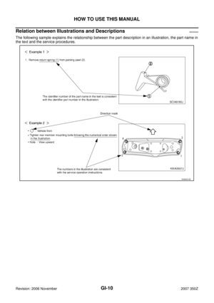
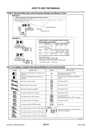
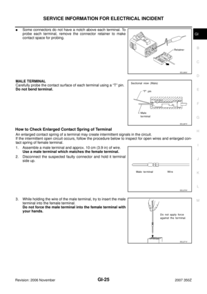
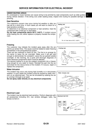
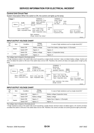
Control Unit Circuit Test
System Description:When the switch is ON, the control unit lights up the lamp.
INPUT-OUTPUT VOLTAGE CHART
The voltage value is based on the body ground.
*:If high resistance exists in the switch side circuit (caused by a single strand), terminal 1 does not detect battery voltage. Control unit
does not detect the switch is ON even if the switch does not turn ON. Therefore, the control unit does not supply power to light up the
lamp.
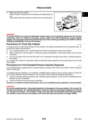
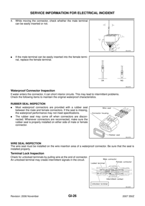
INPUT-OUTPUT VOLTAGE CHART
The voltage value is based on the body ground.
*:If high resistance exists in the switch side circuit (caused by a single strand), terminal 2 does not detect approx. 0V. Control unit does
not detect the switch is ON even if the switch does not turn ON. Therefore, the control unit does not control ground to light up the lamp.
MGI034A
Pin
No.Item ConditionVoltage
value [V]In case of high resistance such as single strand [V] *
1 SwitchSwitch ON Battery voltage Lower than battery voltage Approx. 8 (Example)
Switch OFF Approx. 0 Approx. 0
2LampSwitch ON Battery voltage Approx. 0 (Inoperative lamp)
Switch OFF Approx. 0 Approx. 0
MGI035A
Pin
No.Item ConditionVo l ta g e
value [V]In case of high resistance such as single strand [V] *
1LampSwitch ON Approx. 0 Battery voltage (Inoperative lamp)
Switch OFF Battery voltage Battery voltage
2 SwitchSwitch ON Approx. 0 Higher than 0 Approx. 4 (Example)
Switch OFF Approx. 5 Approx. 5
Page 35 of 54

SERVICE INFORMATION FOR ELECTRICAL INCIDENT
GI-35
C
D
E
F
G
H
I
J
K
L
MB
GI
Revision: 2006 November2007 350Z
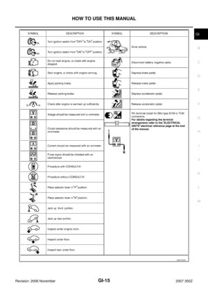
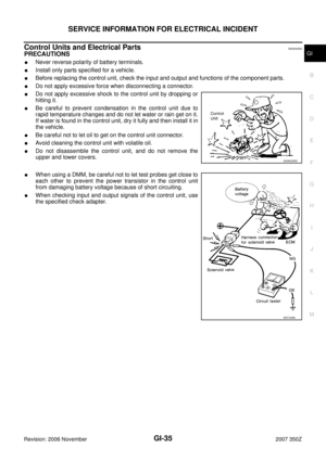
Control Units and Electrical PartsNAS0009Q
PRECAUTIONS
�Never reverse polarity of battery terminals.
�Install only parts specified for a vehicle.
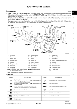
�Before replacing the control unit, check the input and output and functions of the component parts.
�Do not apply excessive force when disconnecting a connector.
�Do not apply excessive shock to the control unit by dropping or
hitting it.
�Be careful to prevent condensation in the control unit due to
rapid temperature changes and do not let water or rain get on it.
If water is found in the control unit, dry it fully and then install it in
the vehicle.
�Be careful not to let oil to get on the control unit connector.
�Avoid cleaning the control unit with volatile oil.
�Do not disassemble the control unit, and do not remove the
upper and lower covers.
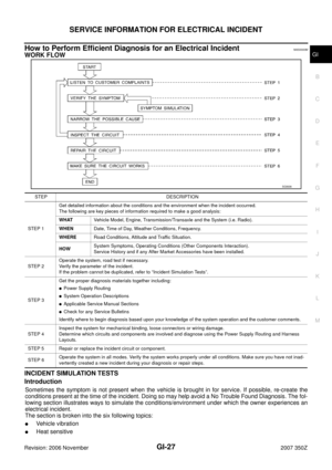
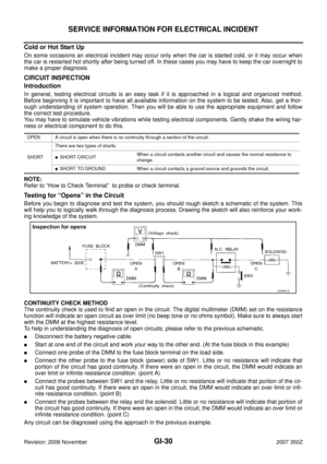
�When using a DMM, be careful not to let test probes get close to
each other to prevent the power transistor in the control unit
from damaging battery voltage because of short circuiting.
�When checking input and output signals of the control unit, use
the specified check adapter.
SAIA0255E
SEF348N
Page 36 of 54
 eq")
GI-36
CONSULT-III/GST CHECKING SYSTEM
Revision: 2006 November2007 350Z
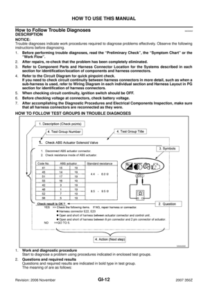
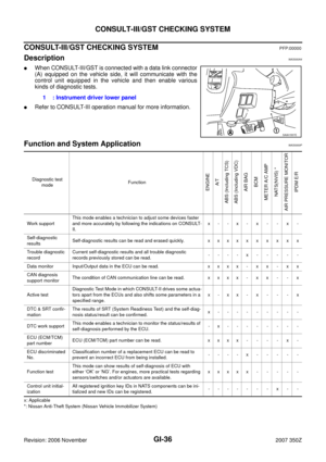
CONSULT-III/GST CHECKING SYSTEMPFP:00000
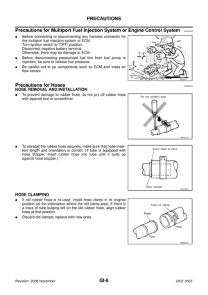
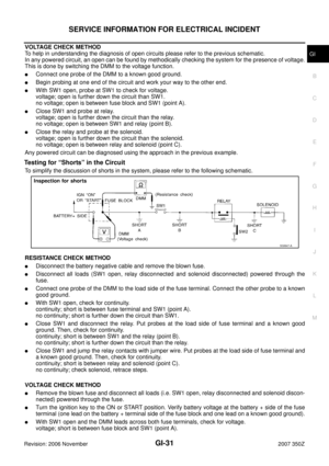
DescriptionNAS000A4
�When CONSULT-III/GST is connected with a data link connector
(A) equipped on the vehicle side, it will communicate with the
control unit equipped in the vehicle and then enable various
kinds of diagnostic tests.
�Refer to CONSULT-III operation manual for more information.
Function and System Application NAS0000P
x: Applicable
*: Nissan Anti-Theft System (Nissan Vehicle Immobilizer System)
1 : Instrument driver lower panel
SAIA1557E
Diagnostic test
modeFunction
ENGINE
A/T
ABS (Including TCS)
ABS (Including VDC)
AIR BAG
BCM
METER A/C AMP
NATS(NVIS) *
AIR PRESSURE MONITOR
IPDM E/R
Work supportThis mode enables a technician to adjust some devices faster
and more accurately by following the indications on CONSULT-
II.x- -x- x - - x -
Self-diagnostic
resultsSelf-diagnostic results can be read and erased quickly. x x x x x x x x x x
Trouble diagnostic
recordCurrent self-diagnostic results and all trouble diagnostic
records previously stored can be read.----x-----
Data monitor Input/Output data in the ECU can be read. x x x x - x x - x x
CAN diagnosis
support monitorThe condition of CAN communication line can be read. x x x x - x x - - x
Active testDiagnostic Test Mode in which CONSULT-II drives some actua-
tors apart from the ECUs and also shifts some parameters in a
specified range.x-xx-x- - -x
DTC & SRT confir-
mationThe results of SRT (System Readiness Test) and the self-diag-
nosis status/result can be confirmed.x---------
DTC work supportThis mode enables a technician to monitor the status/results of
self-diagnosis performed by the ECU.-x--------
ECU (ECM/TCM)
part numberECU (ECM/TCM) part number can be read. x x x x - - - - x -
ECU discriminated
No.Classification number of a replacement ECU can be read to
prevent an incorrect ECU from being installed.----x-----
Function testThis mode can show results of self-diagnosis of ECU with
either ‘OK’ or ‘NG’. For engines, more practical tests regarding
sensors/switches and/or actuators are available.xxxxx-----
Control unit initial-
izationAll registered ignition key IDs in NATS components can be ini-
tialized and new IDs can be registered.---- - - -x - -
Page 37 of 54
 CircuitNAS000A5
INSPECTION PROCEDURE
If the CONSULT-III cannot di")
CONSULT-III/GST CHECKING SYSTEM
GI-37
C
D
E
F
G
H
I
J
K
L
MB
GI
Revision: 2006 November2007 350Z
CONSULT-III Data Link Connector (DLC) CircuitNAS000A5
INSPECTION PROCEDURE
If the CONSULT-III cannot diagnose the system properly, check the following items.
NOTE:
The DDL1 and DDL2 circuits from DLC pins 12, 13, 14 and 15 may be connected to more than one system. A short in a DDL circuit con-
nected to a control unit in one system may affect CONSULT-III access to other systems.Symptom Check item
CONSULT-III cannot access
any system.
�CONSULT-III DLC power supply circuit (Terminal 8) and ground circuit (Terminal 4)
CONSULT-III cannot access
individual system. (Other sys-
tems can be accessed.)
�Power supply and ground circuit for the control unit of the system (For detailed circuit, refer to
wiring diagram for each system.)
�Open or short circuit between the system and CONSULT-III DLC (For detailed circuit, refer to
wiring diagram for each system.)
�Open or short circuit CAN communication line. Refer to LAN-16, "Trouble Diagnosis Flow Chart"
.
Page 38 of 54
GI-38
CONSULT-III/GST CHECKING SYSTEM
Revision: 2006 November2007 350Z
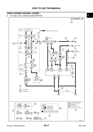
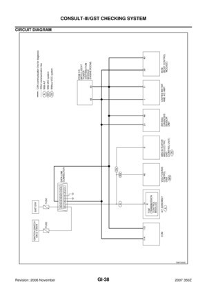
CIRCUIT DIAGRAM
TAWT0053E
Page 39 of 54

LIFTING POINT
GI-39
C
D
E
F
G
H
I
J
K
L
MB
GI
Revision: 2006 November2007 350Z
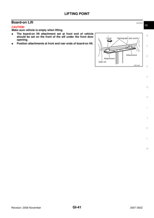
LIFTING POINTPFP:00000
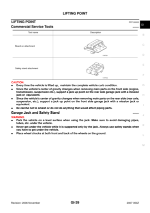
Commercial Service Tools NAS0000U
CAUTION:
�Every time the vehicle is lifted up, maintain the complete vehicle curb condition.
�Since the vehicle's center of gravity changes when removing main parts on the front side (engine,
transmission, suspension etc.), support a jack up point on the rear side garage jack with a mission
jack or equivalent.
�Since the vehicle's center of gravity changes when removing main parts on the rear side (rear axle,
suspension, etc.), support a jack up point on the front side garage jack with a mission jack or
equivalent.
�Be careful not to smash or do not do anything that would affect piping parts.
Garage Jack and Safety Stand NAS0000V
WARNING:
�Park the vehicle on a level surface when using the jack. Make sure to avoid damaging pipes,
tubes, etc. under the vehicle.
�Never get under the vehicle while it is supported only by the jack. Always use safety stands when
you have to get under the vehicle.
�Place wheel chocks at both front and back of the wheels on the ground.
Tool name Description
Board on attachment
Safety stand attachment
S-NT001
S-NT002
Page 40 of 54
GI-40
LIFTING POINT
Revision: 2006 November2007 350Z
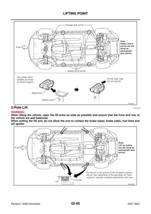
2-Pole Lift NAS0000W
WARNING:
When lifting the vehicle, open the lift arms as wide as possible and ensure that the front and rear of
the vehicle are well balanced.
When setting the lift arm, do not allow the arm to contact the brake tubes, brake cable, fuel lines and
sill spoiler.
PIIB7446E
PAIA0062E