Page 1 of 12
FL-1
FUEL SYSTEM
B ENGINE
CONTENTS
C
D
E
F
G
H
I
J
K
L
M
SECTION FL
A
FL
Revision: 2006 November2007 350Z
FUEL SYSTEM
PRECAUTIONS .......................................................... 2
Precautions for Battery Service ................................ 2
FUEL SYSTEM ........................................................... 3
Checking Fuel Lines ................................................. 3
General Precautions ................................................ 3
FUEL LEVEL SENSOR UNIT, FUEL FILTER AND
FUEL PUMP ASSEMBLY ........................................... 4
Removal and Installation .......................................... 4
REMOVAL ............................................................. 4
INSTALLATION ..................................................... 7INSPECTION AFTER INSTALLATION .................. 8
Disassembly and Assembly ...................................... 8
DISASSEMBLY ..................................................... 8
ASSEMBLY ........................................................... 9
FUEL TANK .............................................................. 10
Removal and Installation ........................................ 10
REMOVAL ........................................................... 10
INSTALLATION ................................................... 11
INSPECTION AFTER INSTALLATION ................ 11
SERVICE DATA AND SPECIFICATIONS (SDS) ...... 12
Standard and Limit .................................................. 12
Tightening Torque ................................................... 12
Page 4 of 12
FL-4
FUEL LEVEL SENSOR UNIT, FUEL FILTER AND FUEL PUMP ASSEMBLY
Revision: 2006 November2007 350Z
FUEL LEVEL SENSOR UNIT, FUEL FILTER AND FUEL PUMP ASSEMBLYPFP:17042
Removal and InstallationNBS000IZ
REMOVAL
WARNING:
Be sure to read “General Precautions” when working on the fuel system. Refer to FL-3, "
General Pre-
cautions" .
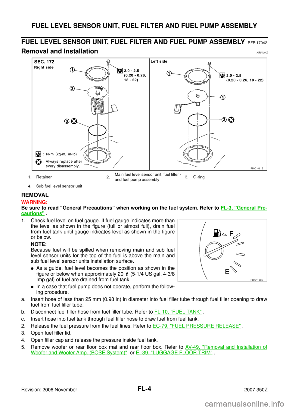
1. Check fuel level on fuel gauge. If fuel gauge indicates more than
the level as shown in the figure (full or almost full), drain fuel
from fuel tank until gauge indicates level as shown in the figure
or below.
NOTE:
Because fuel will be spilled when removing main and sub fuel
level sensor units for the top of the fuel is above the main and
sub fuel level sensor units installation surface.
�As a guide, fuel level becomes the position as shown in the
figure or below when approximately 20 (5-1/4 US gal, 4-3/8
Imp gal) of fuel are drained from fuel tank.
�In a case that fuel pump does not operate, perform the follow-
ing procedure.
a. Insert hose of less than 25 mm (0.98 in) in diameter into fuel filler tube through fuel filler opening to draw
fuel from fuel filler tube.
b. Disconnect fuel filler hose from fuel filler tube. Refer to FL-10, "
FUEL TANK" .
c. Insert hose into fuel tank through fuel filler hose to draw fuel from fuel tank.
2. Release the fuel pressure from the fuel lines. Refer to EC-79, "
FUEL PRESSURE RELEASE" .
3. Open fuel filler lid.
4. Open filler cap and release the pressure inside fuel tank.
5. Remove woofer or rear floor box mat and rear floor box. Refer to AV- 4 9 , "
Removal and Installation of
Woofer and Woofer Amp. (BOSE System)" or EI-39, "LUGGAGE FLOOR TRIM" .
1. Retainer 2.Main fuel level sensor unit, fuel filter -
and fuel pump assembly3. O-ring
4. Sub fuel level sensor unit
PBIC1061E
PBIC1139E
Page 7 of 12
FUEL LEVEL SENSOR UNIT, FUEL FILTER AND FUEL PUMP ASSEMBLY
FL-7
C
D
E
F
G
H
I
J
K
L
MA
FL
Revision: 2006 November2007 350Z
INSTALLATION
Note the following, and install in the reverse order of removal.
Main and Sub Fuel Level Sensor Unit
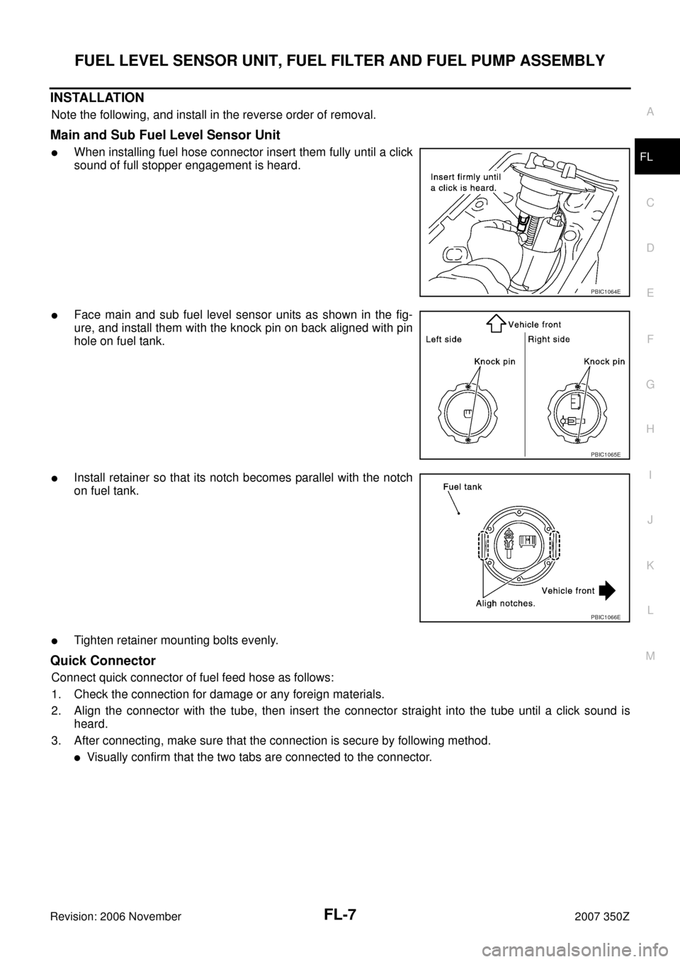
�When installing fuel hose connector insert them fully until a click
sound of full stopper engagement is heard.
�Face main and sub fuel level sensor units as shown in the fig-
ure, and install them with the knock pin on back aligned with pin
hole on fuel tank.
�Install retainer so that its notch becomes parallel with the notch
on fuel tank.
�Tighten retainer mounting bolts evenly.
Quick Connector
Connect quick connector of fuel feed hose as follows:
1. Check the connection for damage or any foreign materials.
2. Align the connector with the tube, then insert the connector straight into the tube until a click sound is
heard.
3. After connecting, make sure that the connection is secure by following method.
�Visually confirm that the two tabs are connected to the connector.
PBIC1064E
PBIC1065E
PBIC1066E
Page 10 of 12
FL-10
FUEL TANK
Revision: 2006 November2007 350Z
FUEL TANKPFP:17202
Removal and InstallationNBS000J1
REMOVAL
WARNING:
Be sure to read “General Precautions” before working on the fuel system. Refer to FL-3, "
General Pre-
cautions" .
�Drain fuel from fuel tank if necessary. Refer to FL-4, "REMOVAL" .
�Perform work on level place.
1. Perform steps 2 to 7 of “REMOVAL” in “ FUEL LEVEL SENSOR UNIT, FUEL FILTER AND FUEL PUMP
ASSEMBLY” on main and sub fuel level sensor units. Refer to FL-4, "
REMOVAL" .
2. Remove tunnel stay. Refer to RSU-5, "
REAR SUSPENSION ASSEMBLY" .
3. Remove exhaust front tube, center muffler and main muffler. Refer to EX-3, "
EXHAUST SYSTEM" .
4. Remove propeller shaft. Refer to PR-5, "
REAR PROPELLER SHAFT" .
CAUTION:
Do not impact or damage propeller shaft tube.
5. Remove parking rear brake cables. Refer to PB-4, "
PARKING BRAKE CONTROL" .
6. Remove rear suspension assembly. Refer to RSU-5, "
REAR SUSPENSION ASSEMBLY" .
7. Remove fuel tank protector.
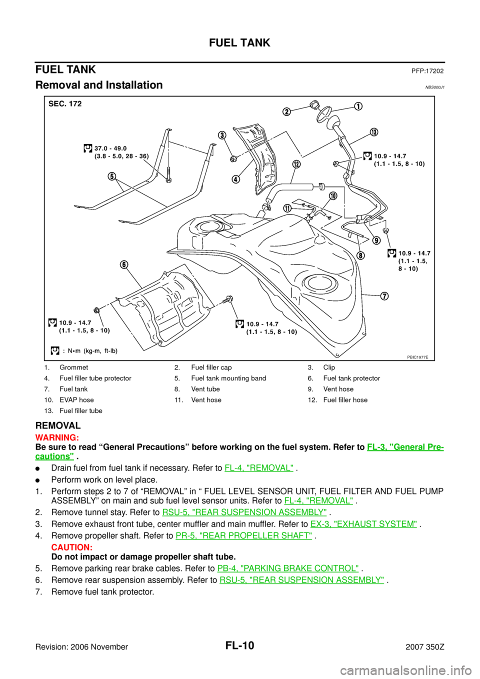
1. Grommet 2. Fuel filler cap 3. Clip
4. Fuel filler tube protector 5. Fuel tank mounting band 6. Fuel tank protector
7. Fuel tank 8. Vent tube 9. Vent hose
10. EVAP hose 11. Vent hose 12. Fuel filler hose
13. Fuel filler tube
PBIC1977E
Page 11 of 12
FUEL TANK
FL-11
C
D
E
F
G
H
I
J
K
L
MA
FL
Revision: 2006 November2007 350Z
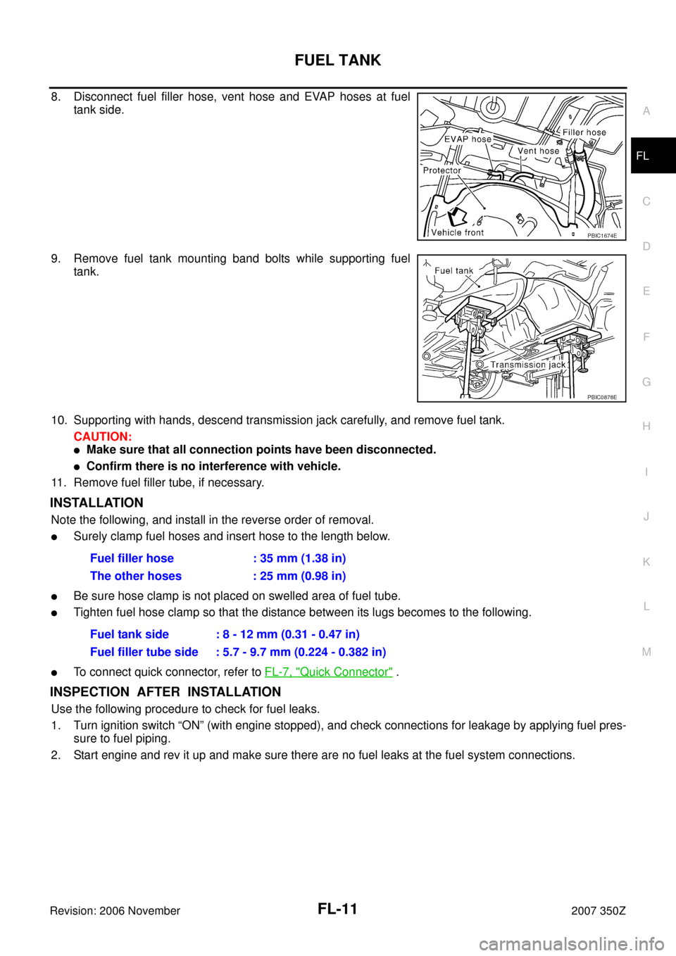
8. Disconnect fuel filler hose, vent hose and EVAP hoses at fuel
tank side.
9. Remove fuel tank mounting band bolts while supporting fuel
tank.
10. Supporting with hands, descend transmission jack carefully, and remove fuel tank.
CAUTION:
�Make sure that all connection points have been disconnected.
�Confirm there is no interference with vehicle.
11. Remove fuel filler tube, if necessary.
INSTALLATION
Note the following, and install in the reverse order of removal.
�Surely clamp fuel hoses and insert hose to the length below.
�Be sure hose clamp is not placed on swelled area of fuel tube.
�Tighten fuel hose clamp so that the distance between its lugs becomes to the following.
�To connect quick connector, refer to FL-7, "Quick Connector" .
INSPECTION AFTER INSTALLATION
Use the following procedure to check for fuel leaks.
1. Turn ignition switch “ON” (with engine stopped), and check connections for leakage by applying fuel pres-
sure to fuel piping.
2. Start engine and rev it up and make sure there are no fuel leaks at the fuel system connections.
PBIC1674E
PBIC0878E
Fuel filler hose : 35 mm (1.38 in)
The other hoses : 25 mm (0.98 in)
Fuel tank side : 8 - 12 mm (0.31 - 0.47 in)
Fuel filler tube side : 5.7 - 9.7 mm (0.224 - 0.382 in)