Page 3 of 12

FUEL SYSTEM
FL-3
C
D
E
F
G
H
I
J
K
L
MA
FL
Revision: 2006 November2007 350Z
FUEL SYSTEMPFP:17503
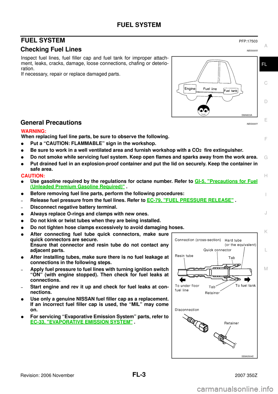
Checking Fuel LinesNBS000IX
Inspect fuel lines, fuel filler cap and fuel tank for improper attach-
ment, leaks, cracks, damage, loose connections, chafing or deterio-
ration.
If necessary, repair or replace damaged parts.
General PrecautionsNBS000IY
WARNING:
When replacing fuel line parts, be sure to observe the following.
�Put a “CAUTION: FLAMMABLE” sign in the workshop.
�Be sure to work in a well ventilated area and furnish workshop with a CO2 fire extinguisher.
�Do not smoke while servicing fuel system. Keep open flames and sparks away from the work area.
�Put drained fuel in an explosion-proof container and put the lid on securely. Keep the container in
safe area.
CAUTION:
�Use gasoline required by the regulations for octane number. Refer to GI-5, "Precautions for Fuel
(Unleaded Premium Gasoline Required)" .
�Before removing fuel line parts, perform the following procedures:
–Release fuel pressure from the fuel lines. Refer to EC-79, "FUEL PRESSURE RELEASE" .
–Disconnect negative battery terminal.
�Always replace O-rings and clamps with new ones.
�Do not kink or twist tubes when they are being installed.
�Do not tighten hose clamps excessively to avoid damaging hoses.
�After connecting fuel tube quick connectors, make sure
quick connectors are secure.
Ensure that connector and resin tube do not contact any
adjacent parts.
�After installing tubes, make sure there is no fuel leakage at
connections in the following steps.
–Apply fuel pressure to fuel lines with turning ignition switch
“ON” (with engine stopped). Then check for fuel leaks at
connections.
–Start engine and rev it up and check for fuel leaks at con-
nections.
�Use only a genuine NISSAN fuel filler cap as a replacement.
If an incorrect fuel filler cap is used, the “MIL” may come
on.
�For servicing “Evaporative Emission System” parts, refer to
EC-33, "
EVAPORATIVE EMISSION SYSTEM" .
SMA803A
SBIA0504E
Page 7 of 12

FUEL LEVEL SENSOR UNIT, FUEL FILTER AND FUEL PUMP ASSEMBLY
FL-7
C
D
E
F
G
H
I
J
K
L
MA
FL
Revision: 2006 November2007 350Z
INSTALLATION
Note the following, and install in the reverse order of removal.
Main and Sub Fuel Level Sensor Unit
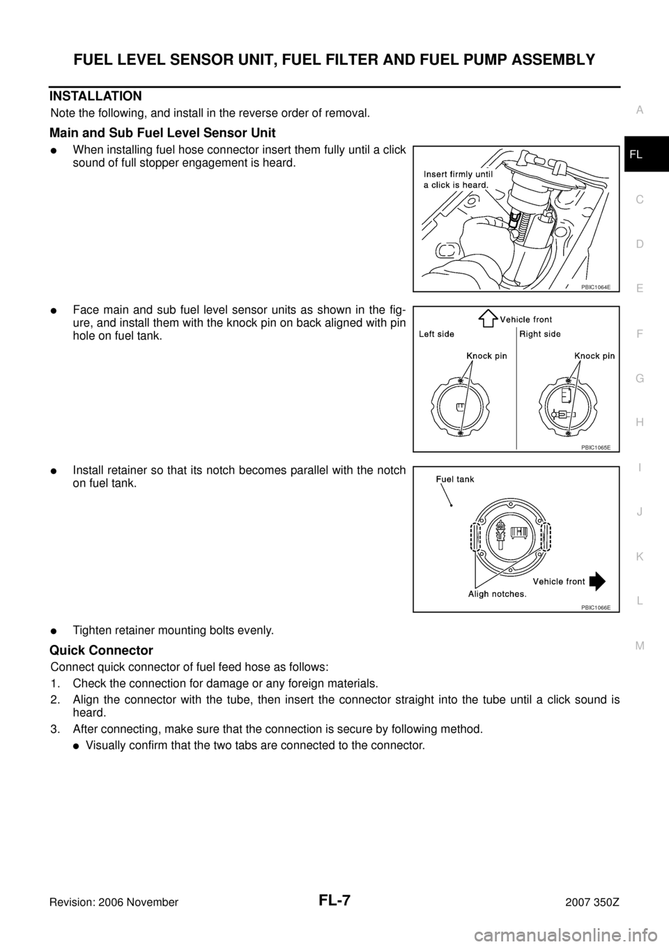
�When installing fuel hose connector insert them fully until a click
sound of full stopper engagement is heard.
�Face main and sub fuel level sensor units as shown in the fig-
ure, and install them with the knock pin on back aligned with pin
hole on fuel tank.
�Install retainer so that its notch becomes parallel with the notch
on fuel tank.
�Tighten retainer mounting bolts evenly.
Quick Connector
Connect quick connector of fuel feed hose as follows:
1. Check the connection for damage or any foreign materials.
2. Align the connector with the tube, then insert the connector straight into the tube until a click sound is
heard.
3. After connecting, make sure that the connection is secure by following method.
�Visually confirm that the two tabs are connected to the connector.
PBIC1064E
PBIC1065E
PBIC1066E
Page 8 of 12

FL-8
FUEL LEVEL SENSOR UNIT, FUEL FILTER AND FUEL PUMP ASSEMBLY
Revision: 2006 November2007 350Z
�Pull the tube and the connector to make sure they are
securely connected.
Inspection Hole Cover
1. Install inspection hole cover with direction mark (arrow) facing front of vehicle.
2. Lock clips by turning counter-clockwise.
INSPECTION AFTER INSTALLATION
Use the following procedure to check for fuel leaks.
1. Turn ignition switch “ON” (with engine stopped), then check connections for leaks by applying fuel pres-
sure to fuel piping.
2. Start engine and rev it up and make sure there are no fuel leaks at the fuel system connections.
Disassembly and AssemblyNBS000J0
CAUTION:
Sub fuel level sensor unit cannot be disassembled and should be replaced as a unit.
DISASSEMBLY
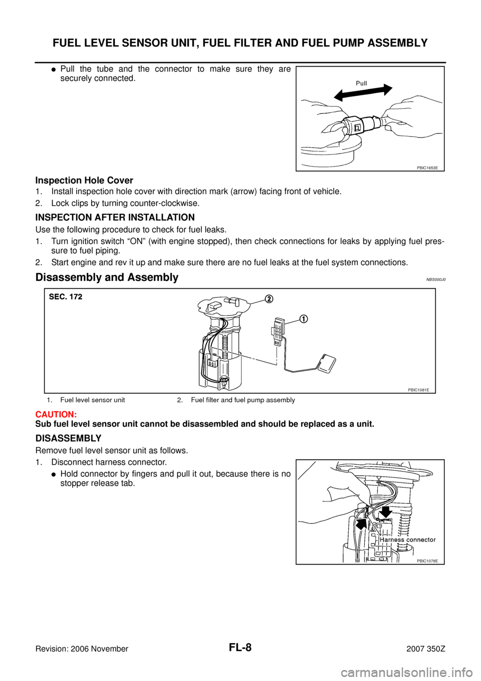
Remove fuel level sensor unit as follows.
1. Disconnect harness connector.
�Hold connector by fingers and pull it out, because there is no
stopper release tab.
PBIC1653E
1. Fuel level sensor unit 2. Fuel filter and fuel pump assembly
PBIC1081E
PBIC1078E
Page 9 of 12
FUEL LEVEL SENSOR UNIT, FUEL FILTER AND FUEL PUMP ASSEMBLY
FL-9
C
D
E
F
G
H
I
J
K
L
MA
FL
Revision: 2006 November2007 350Z
2. Using suitable tool, pull up tabs points as shown in the figure
(two points) to release the lock.
CAUTION:
Be careful not to damage it.
3. After fixing tabs are disengaged, slide fuel level sensor unit out
in direction shown by the arrow.
CAUTION:
Do not disassemble fuel filter and fuel pump assembly.
ASSEMBLY
1. Check for damage of fuel level sensor unit installation position on the side of fuel filter and fuel pump
assembly.
2. Slide fuel level sensor unit until it aligns to installation groove, then insert it until it stops.
�Insert until you hear a “click” sound and actually feel the engagement.
�After inserting, apply force in reverse direction (removal direction) to ensure it cannot be pulled out.
3. Connect harness connector.
�Securely insert harness connector until it stops.
PBIC1654E
PBIC1080E