FSU-12
COIL SPRING AND SHOCK ABSORBER
Revision: 2006 November2007 350Z
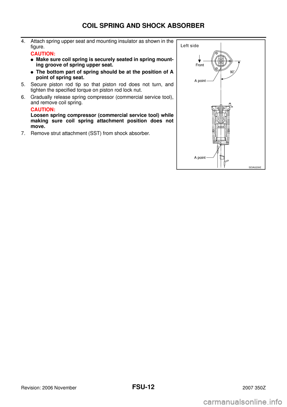
4. Attach spring upper seat and mounting insulator as shown in the
figure.
CAUTION:
�Make sure coil spring is securely seated in spring mount-
ing groove of spring upper seat.
�The bottom part of spring should be at the position of A
point of spring seat.
5. Secure piston rod tip so that piston rod does not turn, and
tighten the specified torque on piston rod lock nut.
6. Gradually release spring compressor (commercial service tool),
and remove coil spring.
CAUTION:
Loosen spring compressor (commercial service tool) while
making sure coil spring attachment position does not
move.
7. Remove strut attachment (SST) from shock absorber.
SEIA0239E
TRANSVERSE LINK
FSU-13
C
D
F
G
H
I
J
K
L
MA
B
FSU
Revision: 2006 November2007 350Z
TRANSVERSE LINKPFP:54500
Removal and InstallationNES0000B
REMOVAL
1. Remove tires from vehicle with power tool.
2. Remove undercover with power tool.
3. Remove mounting nut and washer on lower portion of stabilizer connecting rod with power tool.
4. Remove mounting nut between transverse link and shock absorber on lower position.
5. Remove mounting nut between transverse link and front suspension member with power tool.
6. Remove transverse link from steering knuckle. Refer to FAX-4, "
FRONT WHEEL HUB AND KNUCKLE" .
7. Remove transverse link from vehicle.
INSPECTION AFTER REMOVAL
Visual Inspection
Check transverse link and bushing for deformation, cracks, or damage. If any non-standard condition is found,
replace it.
INSTALLATION
�Refer to FSU-8, "Components" for tightening torque. Install in the reverse order of removal.
NOTE:
Refer to component parts location and do not reuse non-reusable parts.
�Perform final tightening of front suspension member installation position and shock absorber lower side
(rubber bushing) under unladen condition with tires on ground. Check wheel alignment. Refer to FSU-21,
"SERVICE DATA AND SPECIFICATIONS (SDS)" .
FSU-14
UPPER LINK
Revision: 2006 November2007 350Z
UPPER LINKPFP:54524
Removal and InstallationNES0000C
REMOVAL
1. Remove tires from vehicle with power tool.
2. Remove undercover with power tool.
3. Remove shock absorber. Refer to FSU-10, "
COIL SPRING AND SHOCK ABSORBER" .
4. Remove cotter pin of upper link ball joint, then loosen mounting nut.
5. Use a ball joint remover (suitable tool) to remove upper link from steering knuckle. Be careful not to dam-
age ball joint boot.
CAUTION:
Tighten temporarily mounting nut to prevent damage to threads and to prevent ball joint remover
(suitable tool) from coming off.
6. Remove bolts holding upper link to body with power tool.
7. Remove upper link from vehicle.
INSPECTION AFTER REMOVAL
Visual Inspection
�Check upper link and bushing for deformation, cracks, or damage. If any non-standard condition is found,
replace it.
�Check boot of ball joint for cracks, or other damage, and also for grease leakage. If any non-standard con-
dition is found, replace it.
Ball Joint Inspection
�Manually move ball stud to confirm it moves smoothly with no binding.
Swing Torque Inspection
NOTE:
Before measurement, move ball joint at least ten times by hand to check for smooth movement.
�Hook spring balance at ball stud. Confirm spring balance mea-
surement value is within the specifications when ball stud begins
moving.
�If it is outside the specified range, replace upper link assembly.
Rotating Torque Inspection
�Attach mounting nut to ball stud. Check that rotating torque is
within specifications with a preload gauge.
�If it is outside the specified range, replace upper link assembly.Swing torque:
Less than 2.0 N·m (0.20 kg-m, 18 in-lb)
Measured value of spring balance:
Less than 34.8 N (3.5 kg, 7.8 lb)
SEIA0523E
Tool number A: ST3127S000 (J−25765−A)
Rotating torque:
Less than 2.0 N·m (0.20 kg-m, 18 in-lb)
PDIA1258E