Page 603 of 720
DTC P1564 ASCD STEERING SWITCH
EC-603
C
D
E
F
G
H
I
J
K
L
MA
EC
Revision: 2006 November2007 350Z
DTC Confirmation ProcedureNBS000FW
NOTE:
If DTC Confirmation Procedure has been previously conducted, always turn ignition switch OFF and wait at
least 10 seconds before conducting the next test.
WITH CONSULT-III
1. Turn ignition switch ON and wait at least 10 seconds.
2. Press MAIN switch for at least 10 seconds, then release it and wait at least 10 seconds.
3. Press CANCEL switch for at least 10 seconds, then release it and wait at least 10 seconds.
4. Press RESUME/ACCELERATE switch for at least 10 seconds, then release it and wait at least 10 sec-
onds.
5. Press SET/COAST switch for at least 10 seconds, then release it and wait at least 10 seconds.
6. Check DTC.
7. If DTC is detected, go to EC-606, "
Diagnostic Procedure" .
WITH GST
Follow the procedure “WITH CONSULT-III” above.
Page 604 of 720
EC-604
DTC P1564 ASCD STEERING SWITCH
Revision: 2006 November2007 350Z
Wiring DiagramNBS000FX
TBWT1660E
Page 605 of 720
DTC P1564 ASCD STEERING SWITCH
EC-605
C
D
E
F
G
H
I
J
K
L
MA
EC
Revision: 2006 November2007 350Z
Specification data are reference values and are measured between each terminal and ground.
CAUTION:
Do not use ECM ground terminals when measuring input/output voltage. Doing so may result in dam-
age to the ECM's transistor. Use a ground other than ECM terminals, such as the ground.
TER-
MINAL
NO.WIRE
COLORITEM CONDITION DATA (DC Voltage)
101 G/Y ASCD steering switch[Ignition switch: ON]
�ASCD steering switch: OFF4V
[Ignition switch: ON]
�MAIN switch: Pressed0V
[Ignition switch: ON]
�CANCEL switch: Pressed1V
[Ignition switch: ON]
�RESUME/ACCELERATE switch: Pressed3V
[Ignition switch: ON]
�SET/COAST switch: Pressed2V
108 B/YSensor ground
(ASCD steering switch)[Engine is running]
�Warm-up condition
�Idle speed0V
Page 606 of 720
EC-606
DTC P1564 ASCD STEERING SWITCH
Revision: 2006 November2007 350Z
Diagnostic ProcedureNBS000FY
1. CHECK GROUND CONNECTIONS
Models with VDC system, navigation system or telephone
1. Turn ignition switch OFF.
2. Loosen and retighten ground screws on the body. Refer to EC-150, "
Ground Inspection" .
Models without VDC system, navigation system and telephone
1. Turn ignition switch OFF.
2. Loosen and retighten ground screws on the body. Refer to EC-150, "
Ground Inspection" .
OK or NG
OK >> GO TO 2.
NG >> Repair or replace ground connections.
1. Body ground E17 2. Body ground E43 3. Body ground B102
:Vehicle front
1. Body ground E17 2. Body ground E43 3. Body ground F152
(Passenger side view with dash side
finisher removed)
:Vehicle front
PBIB3560E
PBIB3561E
Page 607 of 720

DTC P1564 ASCD STEERING SWITCH
EC-607
C
D
E
F
G
H
I
J
K
L
MA
EC
Revision: 2006 November2007 350Z
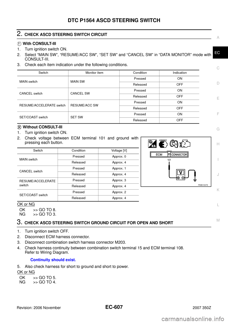
2. CHECK ASCD STEERING SWITCH CIRCUIT
With CONSULT-III
1. Turn ignition switch ON.
2. Select “MAIN SW”, “RESUME/ACC SW”, “SET SW” and “CANCEL SW” in “DATA MONITOR” mode with
CONSULT-III.
3. Check each item indication under the following conditions.
Without CONSULT-III
1. Turn ignition switch ON.
2. Check voltage between ECM terminal 101 and ground with
pressing each button.
OK or NG
OK >> GO TO 8.
NG >> GO TO 3.
3. CHECK ASCD STEERING SWITCH GROUND CIRCUIT FOR OPEN AND SHORT
1. Turn ignition switch OFF.
2. Disconnect ECM harness connector.
3. Disconnect combination switch harness connector M203.
4. Check harness continuity between combination switch terminal 15 and ECM terminal 108.
Refer to Wiring Diagram.
5. Also check harness for short to ground and short to power.
OK or NG
OK >> GO TO 5.
NG >> GO TO 4.
Switch Monitor item Condition Indication
MAIN switch MAIN SWPressed ON
Released OFF
CANCEL switch CANCEL SWPressed ON
Released OFF
RESUME/ACCELERATE switch RESUME/ACC SWPressed ON
Released OFF
SET/COAST switch SET SWPressed ON
Released OFF
Switch Condition Voltage [V]
MAIN switchPressed Approx. 0
Released Approx. 4
CANCEL switchPressed Approx. 1
Released Approx. 4
RESUME/ACCELERATE
switchPressed Approx. 3
Released Approx. 4
SET/COAST switchPressed Approx. 2
Released Approx. 4
PBIB1537E
Continuity should exist.
Page 608 of 720

EC-608
DTC P1564 ASCD STEERING SWITCH
Revision: 2006 November2007 350Z
4. DETECT MALFUNCTIONING PART
Check the following.
�Combination switch (spiral cable)
�Harness for open and short between ECM and combination switch
>> Repair open circuit or short to ground or short to power in harness or connectors.
5. CHECK ASCD STEERING SWITCH INPUT SIGNAL CIRCUIT FOR OPEN AND SHORT
1. Check harness continuity between ECM terminal 101 and combination switch terminal 14.
Refer to Wiring Diagram.
2. Also check harness for short to ground and short to power.
OK or NG
OK >> GO TO 7.
NG >> GO TO 6.
6. DETECT MALFUNCTIONING PART
Check the following.
�Combination switch (spiral cable)
�Harness for open and short between ECM and combination switch
>> Repair open circuit or short to ground or short to power in harness or connectors.
7. CHECK ASCD STEERING SWITCH
Refer to EC-609, "
Component Inspection" .
OK or NG
OK >> GO TO 8.
NG >> Replace steering wheel.
8. CHECK INTERMITTENT INCIDENT
Refer to EC-141, "
TROUBLE DIAGNOSIS FOR INTERMITTENT INCIDENT" .
>>INSPECTION END Continuity should exist.
Page 609 of 720
DTC P1564 ASCD STEERING SWITCH
EC-609
C
D
E
F
G
H
I
J
K
L
MA
EC
Revision: 2006 November2007 350Z
Component InspectionNBS000FZ
ASCD STEERING SWITCH
1. Disconnect combination switch (spiral cable) harness connector M203.
2. Check continuity between combination switch harness connec-
tor terminals 14 and 15 with pushing each switch.
3. If NG, replace ASCD steering switch.
Switch Condition Resistance [Ω]
MAIN switchPressed Approx. 0
Released Approx. 4,000
CANCEL switchPressed Approx. 250
Released Approx. 4,000
RESUME/ACCELERATE
switchPressed Approx. 1,480
Released Approx. 4,000
SET/COAST switchPressed Approx. 660
Released Approx. 4,000
PBIB2549E
Page 681 of 720

ASCD INDICATOR
EC-681
C
D
E
F
G
H
I
J
K
L
MA
EC
Revision: 2006 November2007 350Z
ASCD INDICATORPFP:24814
Component DescriptionNBS000IE
ASCD indicator lamp illuminates to indicate ASCD operation status. Lamp has two indicators, CRUISE, SET,
and is integrated in combination meter.
CRUISE indicator illuminates when MAIN switch on ASCD steering switch is turned ON to indicated that
ASCD system is ready for operation.
SET indicator illuminates when following conditions are met.
�CRUISE indicator is illuminated.
�SET/COAST switch on ASCD steering switch is turned ON while vehicle speed is within the range of
ASCD setting.
SET indicator remains lit during ASCD control.
Refer to EC-30, "
AUTOMATIC SPEED CONTROL DEVICE (ASCD)" for the ASCD function.
CONSULT-III Reference Value in Data Monitor ModeNBS000IF
Specification data are reference value.
MONITOR ITEM CONDITION SPECIFICATION
CRUISE LAMP
�Ignition switch: ONMAIN switch: Pressed at the 1st time →
at the 2nd timeON → OFF
SET LAMP
�MAIN switch: ON
�When vehicle speed is between
40 km/h (25 MPH) and 144 km/h
(89MPH)ASCD: Operating ON
ASCD: Not operating OFF