Page 194 of 720

EC-194
DTC P0078 P0084 EVT CONTROL MAGNET RETARDER
Revision: 2006 November2007 350Z
Specification data are reference values and are measured between each terminal and ground.
Pulse signal is measured by CONSULT-III.
CAUTION:
Do not use ECM ground terminals when measuring input/output voltage. Doing so may result in dam-
age to the ECM's transistor. Use a ground other than ECM terminals, such as the ground.
: Average voltage for pulse signal (Actual pulse signal can be confirmed by oscilloscope.)TER-
MINAL
NO.WIRE
COLORITEM CONDITION DATA (DC Voltage)
7Y/RExhaust valve timing control
magnet retarder (bank 2)[Engine is running]
�Warm-up condition
�Idle speedBATTERY VOLTAGE
(11 - 14V)
[Engine is running]
�Warm-up condition
�Around 2,500 rpm while the engine speed is
rising7 - 12V
24 BR/YECM relay
(Self shut-off)[Engine is running]
[Ignition switch: OFF]
�For a few seconds after turning ignition
switch OFF0 - 1.5V
[Ignition switch: OFF]
�More than a few seconds after turning igni-
tion switch OFFBATTERY VOLTAGE
(11 - 14V)
125 R Power supply for ECM[Ignition switch: ON]BATTERY VOLTAGE
(11 - 14V)
PBIB3542E
Page 201 of 720
DTC P0101, P010B MAF SENSOR
EC-201
C
D
E
F
G
H
I
J
K
L
MA
EC
Revision: 2006 November2007 350Z
Specification data are reference values and are measured between each terminal and ground.
CAUTION:
Do not use ECM ground terminals when measuring input/output voltage. Doing so may result in dam-
age to the ECM's transistor. Use a ground other than ECM terminals, such as the ground.
TER-
MINAL
NO.WIRE
COLORITEM CONDITION DATA (DC Voltage)
24 BR/YECM relay
(Self shut-off)[Engine is running]
[Ignition switch: OFF]
�For a few seconds after turning ignition
switch OFF0 - 1.5V
68 BSensor ground
[Mass air flow sensor
(bank1), Intake air tempera-
ture sensor (bank 1)][Engine is running]
�Warm-up condition
�Idle speed0V
77 L/WMass air flow sensor
(bank1)[Engine is running]
�Warm-up condition
�Idle speed0.8 - 1.1V
[Engine is running]
�Warm-up condition
�Engine speed: 2,500 rpm1.4 - 1.7V
125 R Power supply for ECM[Ignition switch: ON]BATTERY VOLTAGE
(11 - 14V)
Page 203 of 720

DTC P0101, P010B MAF SENSOR
EC-203
C
D
E
F
G
H
I
J
K
L
MA
EC
Revision: 2006 November2007 350Z
Specification data are reference values and are measured between each terminal and ground.
CAUTION:
Do not use ECM ground terminals when measuring input/output voltage. Doing so may result in dam-
age to the ECM's transistor. Use a ground other than ECM terminals, such as the ground.
Diagnostic ProcedureNBS00055
1. INSPECTION START
Which malfunction (A or B) is duplicated?
A or B
A>>GO TO 3.
B>>GO TO 2.
2. CHECK INTAKE SYSTEM
Check the following for connection.
�Air duct
�Va c u u m h o s e s
�Intake air passage between air duct and intake manifold
OK or NG
OK >> GO TO 3.
NG >> Reconnect the parts.
TER-
MINAL
NO.WIRE
COLORITEM CONDITION DATA (DC Voltage)
24 BR/YECM relay
(Self shut-off)[Engine is running]
[Ignition switch: OFF]
�For a few seconds after turning ignition
switch OFF0 - 1.5V
79 GY/RMass air flow sensor
(bank2)[Engine is running]
�Warm-up condition
�Idle speed0.8 - 1.1V
[Engine is running]
�Warm-up condition
�Engine speed: 2,500 rpm1.4 - 1.7V
94 L/YSensor ground
[Mass air flow sensor (bank
2)][Engine is running]
�Warm-up condition
�Idle speed0V
125 R Power supply for ECM[Ignition switch: ON]BATTERY VOLTAGE
(11 - 14V)
Page 211 of 720
DTC P0102, P0103, P010C, P010D MAF SENSOR
EC-211
C
D
E
F
G
H
I
J
K
L
MA
EC
Revision: 2006 November2007 350Z
Specification data are reference values and are measured between each terminal and ground.
CAUTION:
Do not use ECM ground terminals when measuring input/output voltage. Doing so may result in dam-
age to the ECM's transistor. Use a ground other than ECM terminals, such as the ground.
TER-
MINAL
NO.WIRE
COLORITEM CONDITION DATA (DC Voltage)
24 BR/YECM relay
(Self shut-off)[Engine is running]
[Ignition switch: OFF]
�For a few seconds after turning ignition
switch OFF0 - 1.5V
68 BSensor ground
[Mass air flow sensor
(bank1), Intake air tempera-
ture sensor (bank 1)][Engine is running]
�Warm-up condition
�Idle speed0V
77 L/WMass air flow sensor
(bank1)[Engine is running]
�Warm-up condition
�Idle speed0.8 - 1.1V
[Engine is running]
�Warm-up condition
�Engine speed: 2,500 rpm1.4 - 1.7V
125 R Power supply for ECM[Ignition switch: ON]BATTERY VOLTAGE
(11 - 14V)
Page 213 of 720

DTC P0102, P0103, P010C, P010D MAF SENSOR
EC-213
C
D
E
F
G
H
I
J
K
L
MA
EC
Revision: 2006 November2007 350Z
Specification data are reference values and are measured between each terminal and ground.
CAUTION:
Do not use ECM ground terminals when measuring input/output voltage. Doing so may result in dam-
age to the ECM's transistor. Use a ground other than ECM terminals, such as the ground.
Diagnostic ProcedureNBS006U2
1. INSPECTION START
Confirm the detected DTC.
Which DTC is detected?
P0102, P010C>>GO TO 2.
P0103, P010D>>GO TO 3.
2. CHECK INTAKE SYSTEM
Check the following for connection.
�Air duct
�Va c u u m h o s e s
�Intake air passage between air duct and intake manifold
OK or NG
OK >> GO TO 3.
NG >> Reconnect the parts.
TER-
MINAL
NO.WIRE
COLORITEM CONDITION DATA (DC Voltage)
24 BR/YECM relay
(Self shut-off)[Engine is running]
[Ignition switch: OFF]
�For a few seconds after turning ignition
switch OFF0 - 1.5V
79 GY/RMass air flow sensor
(bank2)[Engine is running]
�Warm-up condition
�Idle speed0.8 - 1.1V
[Engine is running]
�Warm-up condition
�Engine speed: 2,500 rpm1.4 - 1.7V
94 L/YSensor ground
[Mass air flow sensor (bank
2)][Engine is running]
�Warm-up condition
�Idle speed0V
125 R Power supply for ECM[Ignition switch: ON]BATTERY VOLTAGE
(11 - 14V)
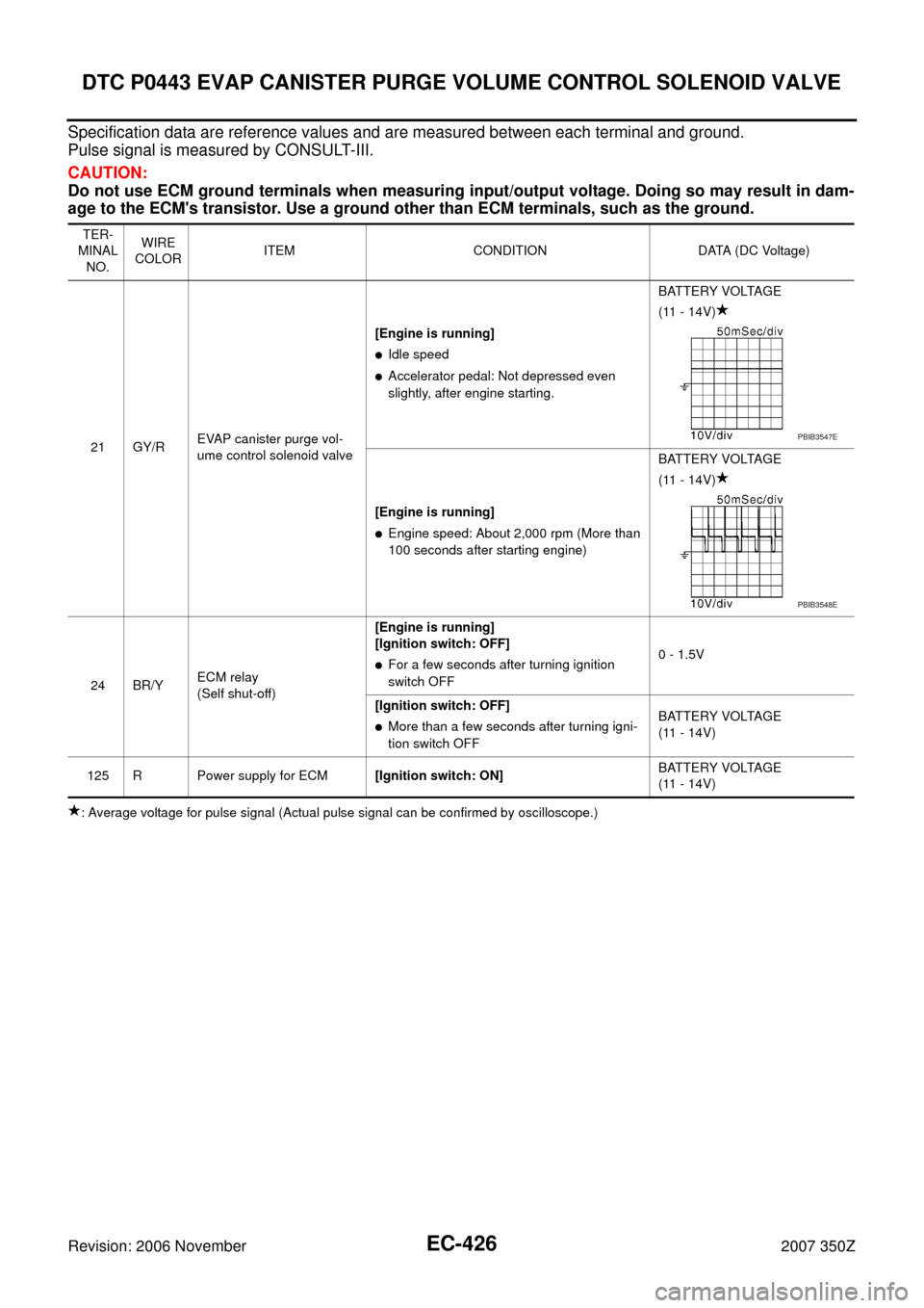
Page 426 of 720

EC-426
DTC P0443 EVAP CANISTER PURGE VOLUME CONTROL SOLENOID VALVE
Revision: 2006 November2007 350Z
Specification data are reference values and are measured between each terminal and ground.
Pulse signal is measured by CONSULT-III.
CAUTION:
Do not use ECM ground terminals when measuring input/output voltage. Doing so may result in dam-
age to the ECM's transistor. Use a ground other than ECM terminals, such as the ground.
: Average voltage for pulse signal (Actual pulse signal can be confirmed by oscilloscope.)TER-
MINAL
NO.WIRE
COLORITEM CONDITION DATA (DC Voltage)
21 GY/REVAP canister purge vol-
ume control solenoid valve[Engine is running]
�Idle speed
�Accelerator pedal: Not depressed even
slightly, after engine starting.BATTERY VOLTAGE
(11 - 14V)
[Engine is running]
�Engine speed: About 2,000 rpm (More than
100 seconds after starting engine)BATTERY VOLTAGE
(11 - 14V)
24 BR/YECM relay
(Self shut-off)[Engine is running]
[Ignition switch: OFF]
�For a few seconds after turning ignition
switch OFF0 - 1.5V
[Ignition switch: OFF]
�More than a few seconds after turning igni-
tion switch OFFBATTERY VOLTAGE
(11 - 14V)
125 R Power supply for ECM[Ignition switch: ON]BATTERY VOLTAGE
(11 - 14V)
PBIB3547E
PBIB3548E
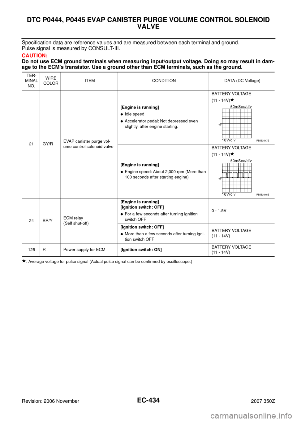
Page 434 of 720

EC-434
DTC P0444, P0445 EVAP CANISTER PURGE VOLUME CONTROL SOLENOID
VALVE
Revision: 2006 November2007 350Z
Specification data are reference values and are measured between each terminal and ground.
Pulse signal is measured by CONSULT-III.
CAUTION:
Do not use ECM ground terminals when measuring input/output voltage. Doing so may result in dam-
age to the ECM's transistor. Use a ground other than ECM terminals, such as the ground.
: Average voltage for pulse signal (Actual pulse signal can be confirmed by oscilloscope.)TER-
MINAL
NO.WIRE
COLORITEM CONDITION DATA (DC Voltage)
21 GY/REVAP canister purge vol-
ume control solenoid valve[Engine is running]
�Idle speed
�Accelerator pedal: Not depressed even
slightly, after engine starting.BATTERY VOLTAGE
(11 - 14V)
[Engine is running]
�Engine speed: About 2,000 rpm (More than
100 seconds after starting engine)BATTERY VOLTAGE
(11 - 14V)
24 BR/YECM relay
(Self shut-off)[Engine is running]
[Ignition switch: OFF]
�For a few seconds after turning ignition
switch OFF0 - 1.5V
[Ignition switch: OFF]
�More than a few seconds after turning igni-
tion switch OFFBATTERY VOLTAGE
(11 - 14V)
125 R Power supply for ECM[Ignition switch: ON]BATTERY VOLTAGE
(11 - 14V)
PBIB3547E
PBIB3548E
Page 440 of 720

EC-440
DTC P0447 EVAP CANISTER VENT CONTROL VALVE
Revision: 2006 November2007 350Z
Specification data are reference values and are measured between each terminal and ground.
CAUTION:
Do not use ECM ground terminals when measuring input/output voltage. Doing so may result in dam-
age to the ECM's transistor. Use a ground other than ECM terminals, such as the ground.
Diagnostic ProcedureNBS00099
1. INSPECTION START
Do you have CONSULT-III?
Ye s o r N o
Yes >> GO TO 2.
No >> GO TO 3.
2. CHECK EVAP CANISTER VENT CONTROL VALVE CIRCUIT
With CONSULT-III
1. Turn ignition switch ON.
2. Select “VENT CONTROL/V” in “ACTIVE TEST” mode with CONSULT-III.
3. Touch “ON/OFF” on CONSULT-III screen.
4. Check for operating sound of the valve.
OK or NG
OK >> GO TO 7.
NG >> GO TO 3.
TER-
MINAL
NO.WIRE
COLORITEM CONDITION DATA (DC Voltage)
24 BR/YECM relay
(Self shut-off)[Engine is running]
[Ignition switch: OFF]
�For a few seconds after turning ignition
switch OFF0 - 1.5V
[Ignition switch: OFF]
�More than a few seconds after turning igni-
tion switch OFFBATTERY VOLTAGE
(11 - 14V)
121 LGEVAP canister vent control
valve[Ignition switch: ON]BATTERY VOLTAGE
(11 - 14V)
125 R Power supply for ECM[Ignition switch: ON]BATTERY VOLTAGE
(11 - 14V)
Clicking noise should be heard.