Page 185 of 720

DTC P0075, P0081 IVT CONTROL SOLENOID VALVE
EC-185
C
D
E
F
G
H
I
J
K
L
MA
EC
Revision: 2006 November2007 350Z
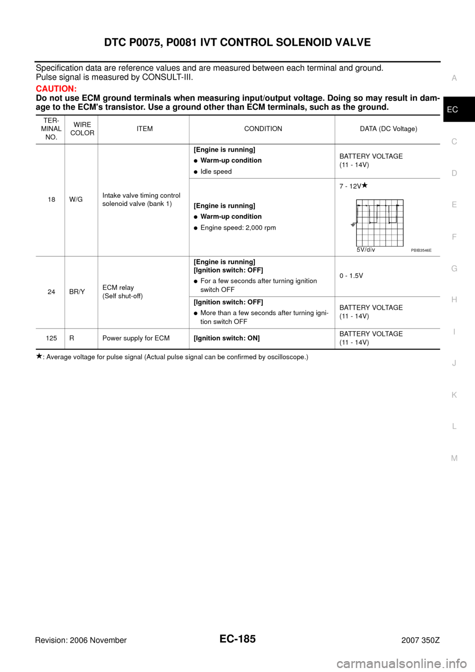
Specification data are reference values and are measured between each terminal and ground.
Pulse signal is measured by CONSULT-III.
CAUTION:
Do not use ECM ground terminals when measuring input/output voltage. Doing so may result in dam-
age to the ECM's transistor. Use a ground other than ECM terminals, such as the ground.
: Average voltage for pulse signal (Actual pulse signal can be confirmed by oscilloscope.)TER-
MINAL
NO.WIRE
COLORITEM CONDITION DATA (DC Voltage)
18 W/GIntake valve timing control
solenoid valve (bank 1)[Engine is running]
�Warm-up condition
�Idle speedBATTERY VOLTAGE
(11 - 14V)
[Engine is running]
�Warm-up condition
�Engine speed: 2,000 rpm7 - 12V
24 BR/YECM relay
(Self shut-off)[Engine is running]
[Ignition switch: OFF]
�For a few seconds after turning ignition
switch OFF0 - 1.5V
[Ignition switch: OFF]
�More than a few seconds after turning igni-
tion switch OFFBATTERY VOLTAGE
(11 - 14V)
125 R Power supply for ECM[Ignition switch: ON]BATTERY VOLTAGE
(11 - 14V)
PBIB3546E
Page 186 of 720
EC-186
DTC P0075, P0081 IVT CONTROL SOLENOID VALVE
Revision: 2006 November2007 350Z
BANK 2
TBWT1622E
Page 187 of 720

DTC P0075, P0081 IVT CONTROL SOLENOID VALVE
EC-187
C
D
E
F
G
H
I
J
K
L
MA
EC
Revision: 2006 November2007 350Z
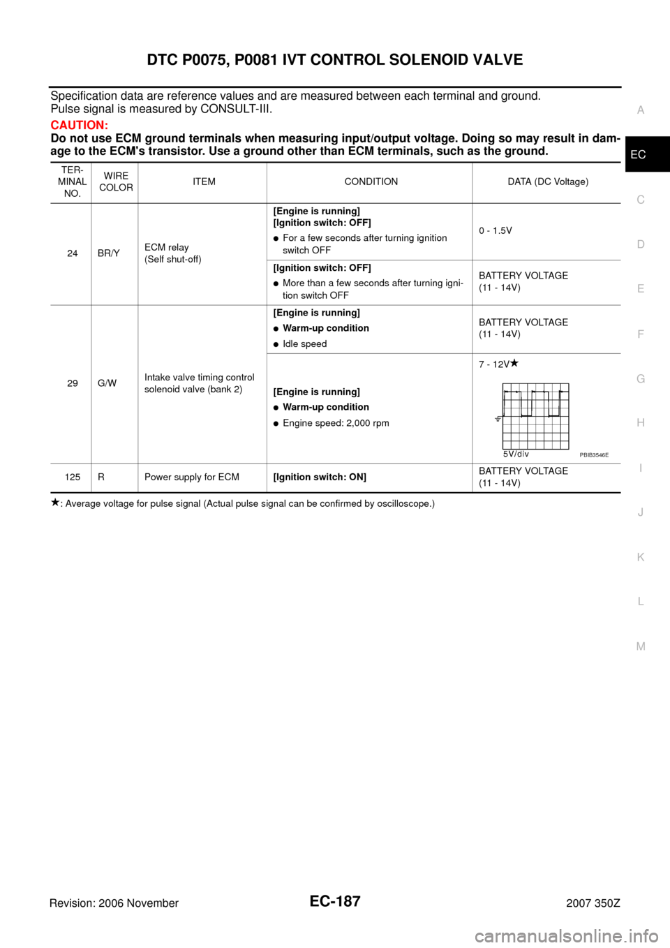
Specification data are reference values and are measured between each terminal and ground.
Pulse signal is measured by CONSULT-III.
CAUTION:
Do not use ECM ground terminals when measuring input/output voltage. Doing so may result in dam-
age to the ECM's transistor. Use a ground other than ECM terminals, such as the ground.
: Average voltage for pulse signal (Actual pulse signal can be confirmed by oscilloscope.)TER-
MINAL
NO.WIRE
COLORITEM CONDITION DATA (DC Voltage)
24 BR/YECM relay
(Self shut-off)[Engine is running]
[Ignition switch: OFF]
�For a few seconds after turning ignition
switch OFF0 - 1.5V
[Ignition switch: OFF]
�More than a few seconds after turning igni-
tion switch OFFBATTERY VOLTAGE
(11 - 14V)
29 G/WIntake valve timing control
solenoid valve (bank 2)[Engine is running]
�Warm-up condition
�Idle speedBATTERY VOLTAGE
(11 - 14V)
[Engine is running]
�Warm-up condition
�Engine speed: 2,000 rpm7 - 12V
125 R Power supply for ECM[Ignition switch: ON]BATTERY VOLTAGE
(11 - 14V)
PBIB3546E
Page 188 of 720

EC-188
DTC P0075, P0081 IVT CONTROL SOLENOID VALVE
Revision: 2006 November2007 350Z
Diagnostic ProcedureNBS000BW
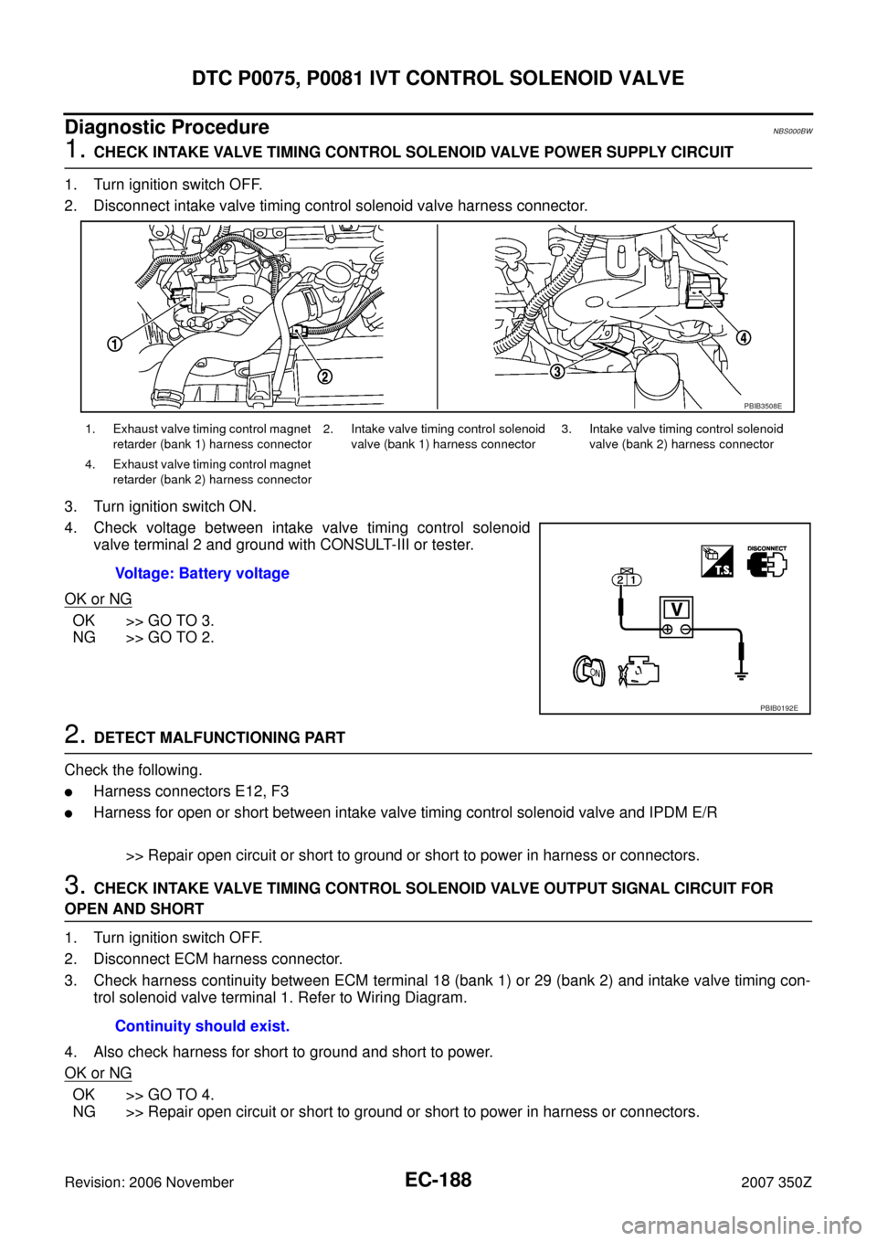
1. CHECK INTAKE VALVE TIMING CONTROL SOLENOID VALVE POWER SUPPLY CIRCUIT
1. Turn ignition switch OFF.
2. Disconnect intake valve timing control solenoid valve harness connector.
3. Turn ignition switch ON.
4. Check voltage between intake valve timing control solenoid
valve terminal 2 and ground with CONSULT-III or tester.
OK or NG
OK >> GO TO 3.
NG >> GO TO 2.
2. DETECT MALFUNCTIONING PART
Check the following.
�Harness connectors E12, F3
�Harness for open or short between intake valve timing control solenoid valve and IPDM E/R
>> Repair open circuit or short to ground or short to power in harness or connectors.
3. CHECK INTAKE VALVE TIMING CONTROL SOLENOID VALVE OUTPUT SIGNAL CIRCUIT FOR
OPEN AND SHORT
1. Turn ignition switch OFF.
2. Disconnect ECM harness connector.
3. Check harness continuity between ECM terminal 18 (bank 1) or 29 (bank 2) and intake valve timing con-
trol solenoid valve terminal 1. Refer to Wiring Diagram.
4. Also check harness for short to ground and short to power.
OK or NG
OK >> GO TO 4.
NG >> Repair open circuit or short to ground or short to power in harness or connectors.
1. Exhaust valve timing control magnet
retarder (bank 1) harness connector2. Intake valve timing control solenoid
valve (bank 1) harness connector3. Intake valve timing control solenoid
valve (bank 2) harness connector
4. Exhaust valve timing control magnet
retarder (bank 2) harness connector
Voltage: Battery voltage
PBIB3508E
PBIB0192E
Continuity should exist.
Page 189 of 720

DTC P0075, P0081 IVT CONTROL SOLENOID VALVE
EC-189
C
D
E
F
G
H
I
J
K
L
MA
EC
Revision: 2006 November2007 350Z
4. CHECK INTAKE VALVE TIMING CONTROL SOLENOID VALVE
Refer to EC-189, "
Component Inspection" .
OK or NG
OK >> GO TO 5.
NG >> Replace malfunctioning intake valve timing control solenoid valve.
5. CHECK INTERMITTENT INCIDENT
Refer to EC-141, "
TROUBLE DIAGNOSIS FOR INTERMITTENT INCIDENT" .
>>INSPECTION END
Component InspectionNBS000BX
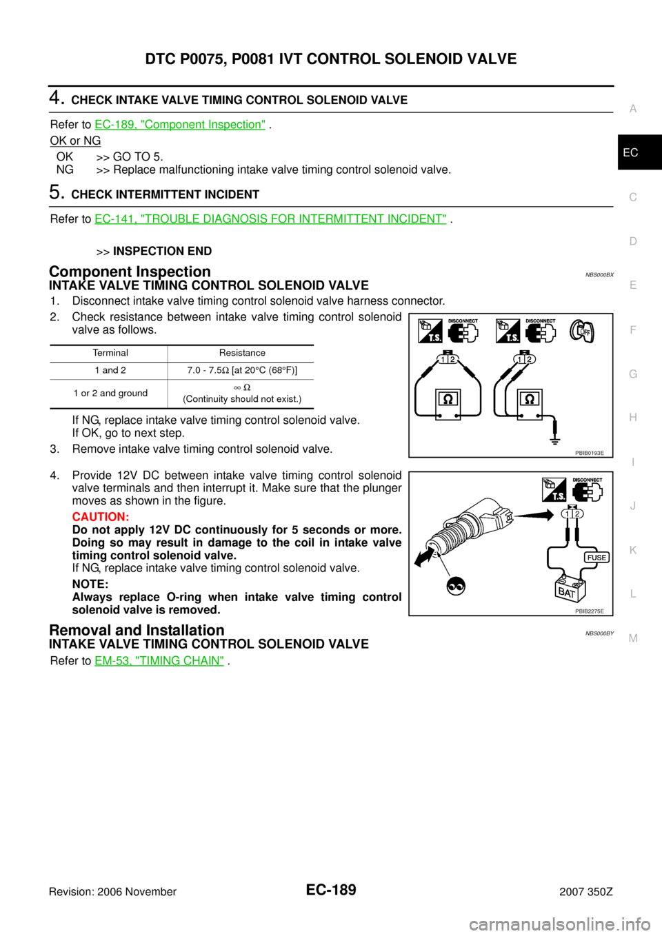
INTAKE VALVE TIMING CONTROL SOLENOID VALVE
1. Disconnect intake valve timing control solenoid valve harness connector.
2. Check resistance between intake valve timing control solenoid
valve as follows.
If NG, replace intake valve timing control solenoid valve.
If OK, go to next step.
3. Remove intake valve timing control solenoid valve.
4. Provide 12V DC between intake valve timing control solenoid
valve terminals and then interrupt it. Make sure that the plunger
moves as shown in the figure.
CAUTION:
Do not apply 12V DC continuously for 5 seconds or more.
Doing so may result in damage to the coil in intake valve
timing control solenoid valve.
If NG, replace intake valve timing control solenoid valve.
NOTE:
Always replace O-ring when intake valve timing control
solenoid valve is removed.
Removal and InstallationNBS000BY
INTAKE VALVE TIMING CONTROL SOLENOID VALVE
Refer to EM-53, "TIMING CHAIN" .
Terminal Resistance
1 and 2 7.0 - 7.5Ω [at 20°C (68°F)]
1 or 2 and ground∞ Ω
(Continuity should not exist.)
PBIB0193E
PBIB2275E