Page 572 of 720
EC-572
DTC P1236, P2118 THROTTLE CONTROL MOTOR
Revision: 2006 November2007 350Z
Wiring DiagramNBS000CJ
BANK 1
TBWT1668E
Page 577 of 720

DTC P1236, P2118 THROTTLE CONTROL MOTOR
EC-577
C
D
E
F
G
H
I
J
K
L
MA
EC
Revision: 2006 November2007 350Z
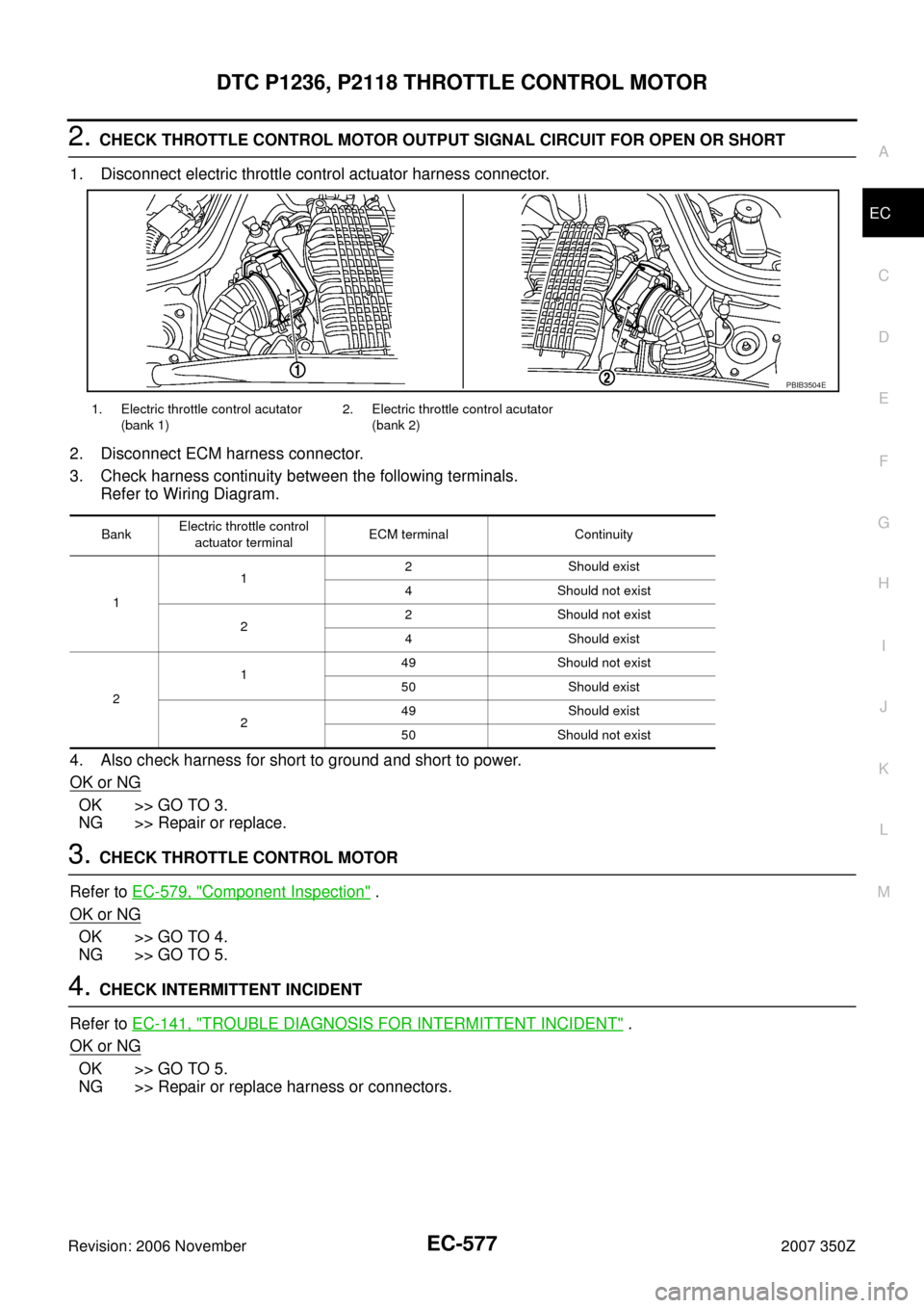
2. CHECK THROTTLE CONTROL MOTOR OUTPUT SIGNAL CIRCUIT FOR OPEN OR SHORT
1. Disconnect electric throttle control actuator harness connector.
2. Disconnect ECM harness connector.
3. Check harness continuity between the following terminals.
Refer to Wiring Diagram.
4. Also check harness for short to ground and short to power.
OK or NG
OK >> GO TO 3.
NG >> Repair or replace.
3. CHECK THROTTLE CONTROL MOTOR
Refer to EC-579, "
Component Inspection" .
OK or NG
OK >> GO TO 4.
NG >> GO TO 5.
4. CHECK INTERMITTENT INCIDENT
Refer to EC-141, "
TROUBLE DIAGNOSIS FOR INTERMITTENT INCIDENT" .
OK or NG
OK >> GO TO 5.
NG >> Repair or replace harness or connectors.
1. Electric throttle control acutator
(bank 1)2. Electric throttle control acutator
(bank 2)
BankElectric throttle control
actuator terminalECM terminal Continuity
112 Should exist
4 Should not exist
22 Should not exist
4 Should exist
2149 Should not exist
50 Should exist
249 Should exist
50 Should not exist
PBIB3504E
Page 584 of 720
EC-584
DTC P1239, P2135 TP SENSOR
Revision: 2006 November2007 350Z
Wiring DiagramNBS000H9
BANK 1
TBWT1672E
Page 589 of 720

DTC P1239, P2135 TP SENSOR
EC-589
C
D
E
F
G
H
I
J
K
L
MA
EC
Revision: 2006 November2007 350Z
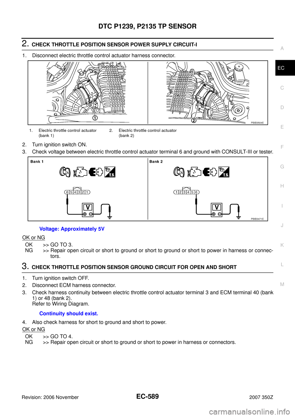
2. CHECK THROTTLE POSITION SENSOR POWER SUPPLY CIRCUIT-I
1. Disconnect electric throttle control actuator harness connector.
2. Turn ignition switch ON.
3. Check voltage between electric throttle control actuator terminal 6 and ground with CONSULT-III or tester.
OK or NG
OK >> GO TO 3.
NG >> Repair open circuit or short to ground or short to ground or short to power in harness or connec-
tors.
3. CHECK THROTTLE POSITION SENSOR GROUND CIRCUIT FOR OPEN AND SHORT
1. Turn ignition switch OFF.
2. Disconnect ECM harness connector.
3. Check harness continuity between electric throttle control actuator terminal 3 and ECM terminal 40 (bank
1) or 48 (bank 2).
Refer to Wiring Diagram.
4. Also check harness for short to ground and short to power.
OK or NG
OK >> GO TO 4.
NG >> Repair open circuit or short to ground or short to power in harness or connectors.
1. Electric throttle control actuator
(bank 1)2. Electric throttle control actuator
(bank 2)
Voltage: Approximately 5V
PBIB3504E
PBIB3471E
Continuity should exist.
Page 590 of 720

EC-590
DTC P1239, P2135 TP SENSOR
Revision: 2006 November2007 350Z
4. CHECK THROTTLE POSITION SENSOR INPUT SIGNAL CIRCUIT FOR OPEN AND SHORT
1. Check harness continuity between the following;
ECM terminal 30 (bank 1) or 31 (bank 2) and electric throttle control actuator terminal 4,
ECM terminal 34 (bank 1) or 35 (bank 2) and electric throttle control actuator terminal 5.
Refer to Wiring Diagram.
2. Also check harness for short to ground and short to power.
OK or NG
OK >> GO TO 5.
NG >> Repair open circuit or short to ground or short to power in harness or connectors.
5. CHECK THROTTLE POSITION SENSOR
Refer to EC-590, "
Component Inspection" .
OK or NG
OK >> GO TO 7.
NG >> GO TO 6.
6. REPLACE ELECTRIC THROTTLE CONTROL ACTUATOR
1. Replace the electric throttle control actuator.
2. Perform EC-77, "
Throttle Valve Closed Position Learning" .
3. Perform EC-77, "
Idle Air Volume Learning" .
>>INSPECTION END
7. CHECK INTERMITTENT INCIDENT
Refer to EC-141, "
TROUBLE DIAGNOSIS FOR INTERMITTENT INCIDENT" .
>>INSPECTION END
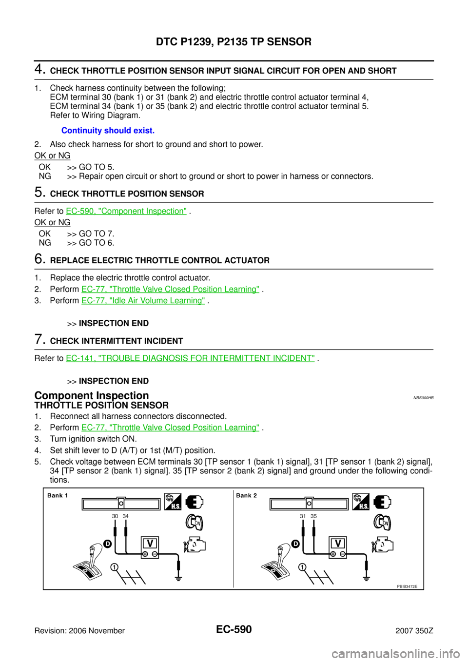
Component InspectionNBS000HB
THROTTLE POSITION SENSOR
1. Reconnect all harness connectors disconnected.
2. Perform EC-77, "
Throttle Valve Closed Position Learning" .
3. Turn ignition switch ON.
4. Set shift lever to D (A/T) or 1st (M/T) position.
5. Check voltage between ECM terminals 30 [TP sensor 1 (bank 1) signal], 31 [TP sensor 1 (bank 2) signal],
34 [TP sensor 2 (bank 1) signal]. 35 [TP sensor 2 (bank 2) signal] and ground under the following condi-
tions.Continuity should exist.
PBIB3472E
Page 594 of 720
EC-594
DTC P1290, P2100, P2103 THROTTLE CONTROL MOTOR RELAY
Revision: 2006 November2007 350Z
Wiring DiagramNBS000CE
BANK 1
TBWT1664E
Page 598 of 720

EC-598
DTC P1290, P2100, P2103 THROTTLE CONTROL MOTOR RELAY
Revision: 2006 November2007 350Z
2. CHECK THROTTLE CONTROL MOTOR RELAY POWER SUPPLY CIRCUIT-II
1. Disconnect ECM harness connector.
2. Disconnect IPDM E/R harness connector E9.
3. Check continuity between ECM terminal 25 and IPDM E/R terminal 47.
Refer to Wiring Diagram.
4. Also check harness for short to ground and short to power.
OK or NG
OK >> GO TO 4.
NG >> GO TO 3.
3. DETECT MALFUNCTIONING PART
Check the following.
�Harness connectors E10, F1
�Harness for open or short between ECM and IPDM E/R
>> Repair open circuit or short to ground or short to power in harness or connectors.
4. CHECK FUSE
1. Disconnect 15A fuse.
2. Check 15A fuse for blown.
OK or NG
OK >> GO TO 8.
NG >> Replace 15A fuse.
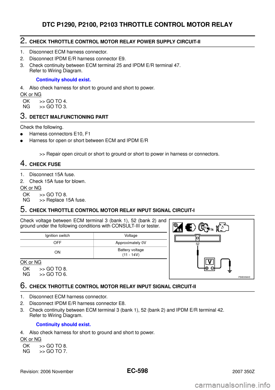
5. CHECK THROTTLE CONTROL MOTOR RELAY INPUT SIGNAL CIRCUIT-I
Check voltage between ECM terminal 3 (bank 1), 52 (bank 2) and
ground under the following conditions with CONSULT-III or tester.
OK or NG
OK >> GO TO 8.
NG >> GO TO 6.
6. CHECK THROTTLE CONTROL MOTOR RELAY INPUT SIGNAL CIRCUIT-II
1. Disconnect ECM harness connector.
2. Disconnect IPDM E/R harness connector E8.
3. Check continuity between ECM terminal 3 (bank 1), 52 (bank 2) and IPDM E/R terminal 42.
Refer to Wiring Diagram.
4. Also check harness for short to ground and short to power.
OK or NG
OK >> GO TO 8.
NG >> GO TO 7.Continuity should exist.
Ignition switch Voltage
OFF Approximately 0V
ONBattery voltage
(11 - 14V)
PBIB3580E
Continuity should exist.
Page 604 of 720
EC-604
DTC P1564 ASCD STEERING SWITCH
Revision: 2006 November2007 350Z
Wiring DiagramNBS000FX
TBWT1660E