Page 657 of 720
DTC P2138 APP SENSOR
EC-657
C
D
E
F
G
H
I
J
K
L
MA
EC
Revision: 2006 November2007 350Z
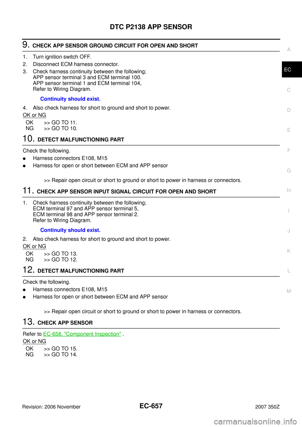
9. CHECK APP SENSOR GROUND CIRCUIT FOR OPEN AND SHORT
1. Turn ignition switch OFF.
2. Disconnect ECM harness connector.
3. Check harness continuity between the following;
APP sensor terminal 3 and ECM terminal 100.
APP sensor terminal 1 and ECM terminal 104,
Refer to Wiring Diagram.
4. Also check harness for short to ground and short to power.
OK or NG
OK >> GO TO 11.
NG >> GO TO 10.
10. DETECT MALFUNCTIONING PART
Check the following.
�Harness connectors E108, M15
�Harness for open or short between ECM and APP sensor
>> Repair open circuit or short to ground or short to power in harness or connectors.
11 . CHECK APP SENSOR INPUT SIGNAL CIRCUIT FOR OPEN AND SHORT
1. Check harness continuity between the following;
ECM terminal 97 and APP sensor terminal 5,
ECM terminal 98 and APP sensor terminal 2.
Refer to Wiring Diagram.
2. Also check harness for short to ground and short to power.
OK or NG
OK >> GO TO 13.
NG >> GO TO 12.
12. DETECT MALFUNCTIONING PART
Check the following.
�Harness connectors E108, M15
�Harness for open or short between ECM and APP sensor
>> Repair open circuit or short to ground or short to power in harness or connectors.
13. CHECK APP SENSOR
Refer to EC-658, "
Component Inspection" .
OK or NG
OK >> GO TO 15.
NG >> GO TO 14.Continuity should exist.
Continuity should exist.
Page 658 of 720
EC-658
DTC P2138 APP SENSOR
Revision: 2006 November2007 350Z
14. REPLACE ACCELERATOR PEDAL ASSEMBLY
1. Replace accelerator pedal assembly.
2. Perform EC-77, "
Accelerator Pedal Released Position Learning" .
3. Perform EC-77, "
Throttle Valve Closed Position Learning" .
4. Perform EC-77, "
Idle Air Volume Learning" .
>>INSPECTION END
15. CHECK INTERMITTENT INCIDENT
Refer to EC-141, "
TROUBLE DIAGNOSIS FOR INTERMITTENT INCIDENT" .
>>INSPECTION END
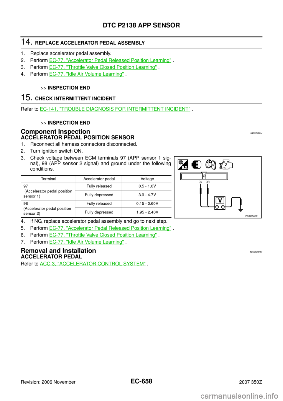
Component InspectionNBS000HJ
ACCELERATOR PEDAL POSITION SENSOR
1. Reconnect all harness connectors disconnected.
2. Turn ignition switch ON.
3. Check voltage between ECM terminals 97 (APP sensor 1 sig-
nal), 98 (APP sensor 2 signal) and ground under the following
conditions.
4. If NG, replace accelerator pedal assembly and go to next step.
5. Perform EC-77, "
Accelerator Pedal Released Position Learning" .
6. Perform EC-77, "
Throttle Valve Closed Position Learning" .
7. Perform EC-77, "
Idle Air Volume Learning" .
Removal and InstallationNBS000HK
ACCELERATOR PEDAL
Refer to ACC-3, "ACCELERATOR CONTROL SYSTEM" .
Terminal Accelerator pedal Voltage
97
(Accelerator pedal position
sensor 1)Fully released 0.5 - 1.0V
Fully depressed 3.9 - 4.7V
98
(Accelerator pedal position
sensor 2)Fully released 0.15 - 0.60V
Fully depressed 1.95 - 2.40V
PBIB3582E
Page 669 of 720
DTC P2A00, P2A03 A/F SENSOR 1
EC-669
C
D
E
F
G
H
I
J
K
L
MA
EC
Revision: 2006 November2007 350Z
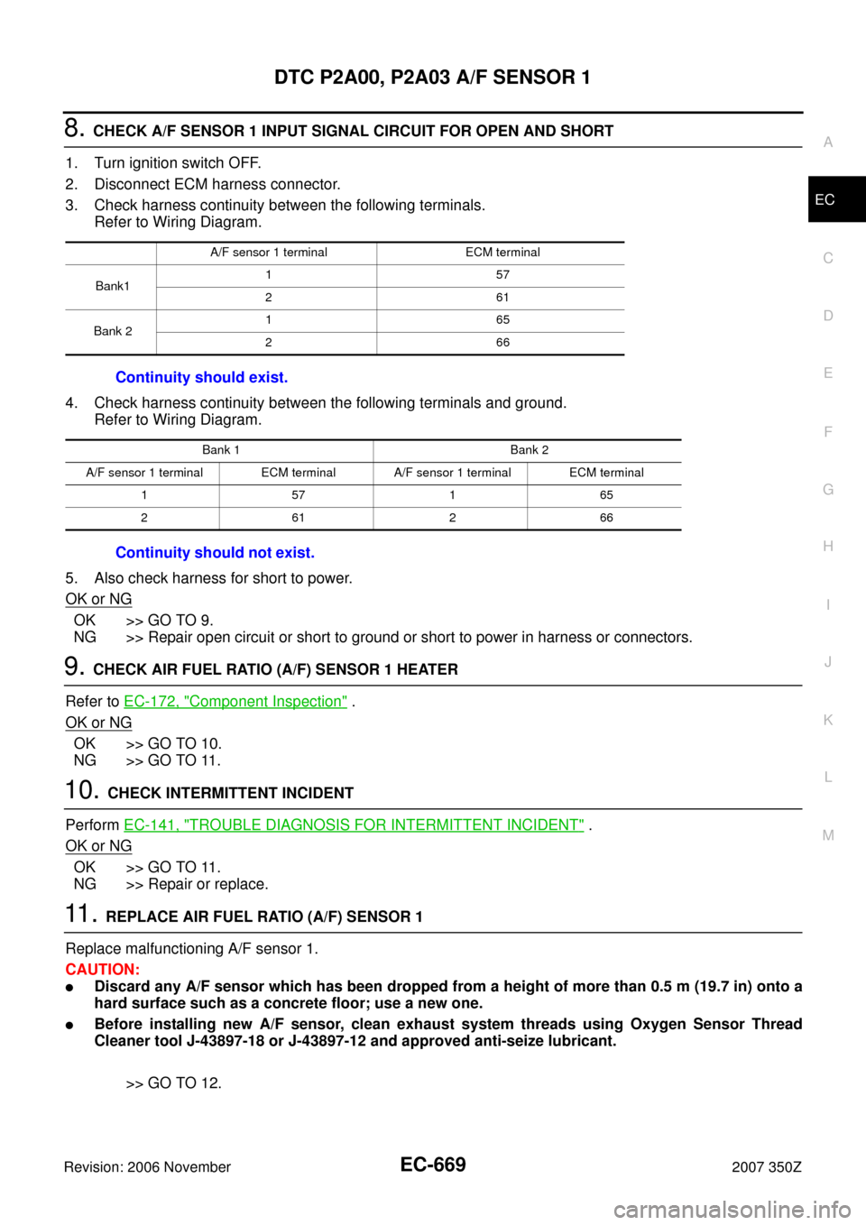
8. CHECK A/F SENSOR 1 INPUT SIGNAL CIRCUIT FOR OPEN AND SHORT
1. Turn ignition switch OFF.
2. Disconnect ECM harness connector.
3. Check harness continuity between the following terminals.
Refer to Wiring Diagram.
4. Check harness continuity between the following terminals and ground.
Refer to Wiring Diagram.
5. Also check harness for short to power.
OK or NG
OK >> GO TO 9.
NG >> Repair open circuit or short to ground or short to power in harness or connectors.
9. CHECK AIR FUEL RATIO (A/F) SENSOR 1 HEATER
Refer to EC-172, "
Component Inspection" .
OK or NG
OK >> GO TO 10.
NG >> GO TO 11.
10. CHECK INTERMITTENT INCIDENT
Perform EC-141, "
TROUBLE DIAGNOSIS FOR INTERMITTENT INCIDENT" .
OK or NG
OK >> GO TO 11.
NG >> Repair or replace.
11 . REPLACE AIR FUEL RATIO (A/F) SENSOR 1
Replace malfunctioning A/F sensor 1.
CAUTION:
�Discard any A/F sensor which has been dropped from a height of more than 0.5 m (19.7 in) onto a
hard surface such as a concrete floor; use a new one.
�Before installing new A/F sensor, clean exhaust system threads using Oxygen Sensor Thread
Cleaner tool J-43897-18 or J-43897-12 and approved anti-seize lubricant.
>> GO TO 12.
A/F sensor 1 terminal ECM terminal
Bank1157
261
Bank 2165
266
Continuity should exist.
Bank 1 Bank 2
A/F sensor 1 terminal ECM terminal A/F sensor 1 terminal ECM terminal
157165
261266
Continuity should not exist.
Page 671 of 720
ASCD BRAKE SWITCH
EC-671
C
D
E
F
G
H
I
J
K
L
MA
EC
Revision: 2006 November2007 350Z
ASCD BRAKE SWITCHPFP:25320
Component DescriptionNBS000I9
When the brake pedal is depressed, ASCD brake switch is turned
OFF and stop lamp switch is turned ON. ECM detects the state of
the brake pedal by this input of two kinds (ON/OFF signal).
Refer to EC-30, "
AUTOMATIC SPEED CONTROL DEVICE (ASCD)"
for the ASCD function.
CONSULT-III Reference Value in Data Monitor ModeNBS000IA
Specification data are reference values.
PBIB1282E
MONITOR ITEM CONDITION SPECIFICATION
BRAKE SW1
(ASCD brake switch)
�Ignition switch: ON
�Brake pedal: Fully released (A/T)
�Brake pedal and clutch pedal: Fully
released (M/T)ON
�Brake pedal: Slightly depressed (A/T)
�Brake pedal and/or clutch pedal:
Slightly depressed (M/T)OFF
BRAKE SW2
(Stop lamp switch)
�Ignition switch: ONBrake pedal: Fully released OFF
Brake pedal: Slightly depressed ON
Page 676 of 720
EC-676
ASCD BRAKE SWITCH
Revision: 2006 November2007 350Z
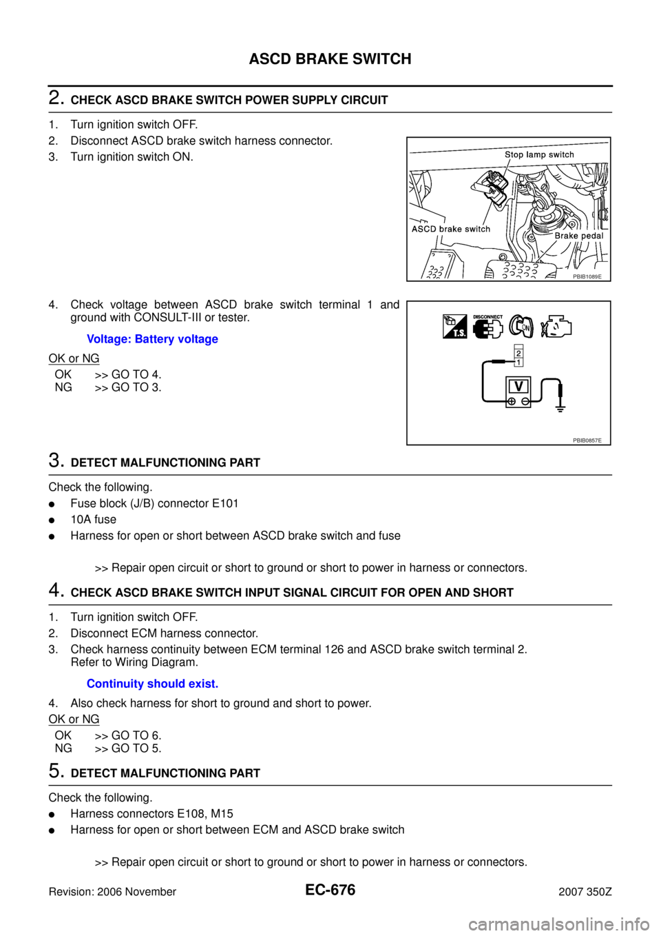
2. CHECK ASCD BRAKE SWITCH POWER SUPPLY CIRCUIT
1. Turn ignition switch OFF.
2. Disconnect ASCD brake switch harness connector.
3. Turn ignition switch ON.
4. Check voltage between ASCD brake switch terminal 1 and
ground with CONSULT-III or tester.
OK or NG
OK >> GO TO 4.
NG >> GO TO 3.
3. DETECT MALFUNCTIONING PART
Check the following.
�Fuse block (J/B) connector E101
�10A fuse
�Harness for open or short between ASCD brake switch and fuse
>> Repair open circuit or short to ground or short to power in harness or connectors.
4. CHECK ASCD BRAKE SWITCH INPUT SIGNAL CIRCUIT FOR OPEN AND SHORT
1. Turn ignition switch OFF.
2. Disconnect ECM harness connector.
3. Check harness continuity between ECM terminal 126 and ASCD brake switch terminal 2.
Refer to Wiring Diagram.
4. Also check harness for short to ground and short to power.
OK or NG
OK >> GO TO 6.
NG >> GO TO 5.
5. DETECT MALFUNCTIONING PART
Check the following.
�Harness connectors E108, M15
�Harness for open or short between ECM and ASCD brake switch
>> Repair open circuit or short to ground or short to power in harness or connectors.
PBIB1089E
Voltage: Battery voltage
PBIB0857E
Continuity should exist.
Page 679 of 720
ASCD BRAKE SWITCH
EC-679
C
D
E
F
G
H
I
J
K
L
MA
EC
Revision: 2006 November2007 350Z
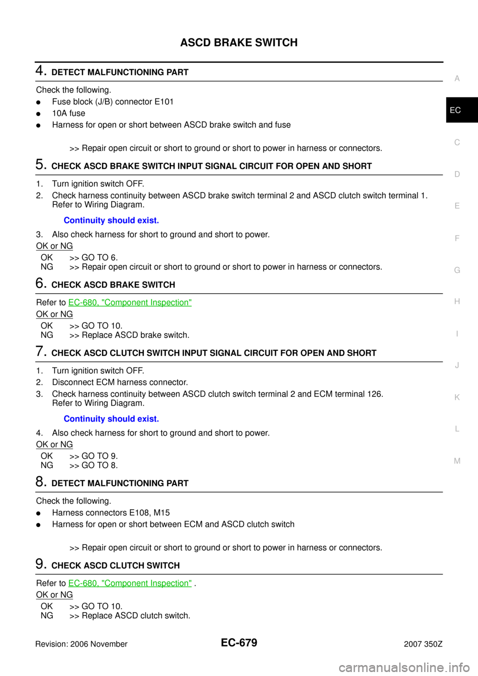
4. DETECT MALFUNCTIONING PART
Check the following.
�Fuse block (J/B) connector E101
�10A fuse
�Harness for open or short between ASCD brake switch and fuse
>> Repair open circuit or short to ground or short to power in harness or connectors.
5. CHECK ASCD BRAKE SWITCH INPUT SIGNAL CIRCUIT FOR OPEN AND SHORT
1. Turn ignition switch OFF.
2. Check harness continuity between ASCD brake switch terminal 2 and ASCD clutch switch terminal 1.
Refer to Wiring Diagram.
3. Also check harness for short to ground and short to power.
OK or NG
OK >> GO TO 6.
NG >> Repair open circuit or short to ground or short to power in harness or connectors.
6. CHECK ASCD BRAKE SWITCH
Refer to EC-680, "
Component Inspection"
OK or NG
OK >> GO TO 10.
NG >> Replace ASCD brake switch.
7. CHECK ASCD CLUTCH SWITCH INPUT SIGNAL CIRCUIT FOR OPEN AND SHORT
1. Turn ignition switch OFF.
2. Disconnect ECM harness connector.
3. Check harness continuity between ASCD clutch switch terminal 2 and ECM terminal 126.
Refer to Wiring Diagram.
4. Also check harness for short to ground and short to power.
OK or NG
OK >> GO TO 9.
NG >> GO TO 8.
8. DETECT MALFUNCTIONING PART
Check the following.
�Harness connectors E108, M15
�Harness for open or short between ECM and ASCD clutch switch
>> Repair open circuit or short to ground or short to power in harness or connectors.
9. CHECK ASCD CLUTCH SWITCH
Refer to EC-680, "
Component Inspection" .
OK or NG
OK >> GO TO 10.
NG >> Replace ASCD clutch switch.Continuity should exist.
Continuity should exist.
Page 684 of 720

EC-684
ELECTRICAL LOAD SIGNAL
Revision: 2006 November2007 350Z
ELECTRICAL LOAD SIGNALPFP:25350
DescriptionNBS000I6
The electrical load signal (Headlamp switch signal, rear window defogger switch signal, etc.) is transferred
through the CAN communication line from BCM to ECM via IPDM E/R.
CONSULT-III Reference Value in Data Monitor ModeNBS000I7
Specification data are reference values.
Diagnostic ProcedureNBS000I8
1. CHECK LOAD SIGNAL CIRCUIT OVERALL FUNCTION-I
1. Turn ignition switch ON.
2. Connect CONSULT-III and select “DATA MONITOR” mode.
3. Select “LOAD SIGNAL” and check indication under the following conditions.
OK or NG
OK >> GO TO 2.
NG >> GO TO 4.
2. CHECK LOAD SIGNAL CIRCUIT OVERALL FUNCTION-II
Check “LOAD SIGNAL” indication under the following conditions.
OK or NG
OK >> GO TO 3.
NG >> GO TO 5.
3. CHECK HEATER FAN SIGNAL CIRCUIT OVERALL FUNCTION
With CONSULT-III
Check “HEATER FAN SW” in “DATA MONITOR” mode with CONSULT-III under the following conditions.
OK or NG
OK >>INSPECTION END
NG >> GO TO 6.
MONITOR ITEM CONDITION SPECIFICATION
LOAD SIGNAL
�Ignition switch: ONRear window defogger switch: ON and/
or lighting switch: 2nd positionON
Rear window defogger switch and light-
ing switch: OFFOFF
HEATER FAN SW
�Engine: After warming up, idle
the engineHeater fan switch: ON ON
Heater fan switch: OFF OFF
Condition Indication
Rear window defogger switch: ON ON
Rear window defogger switch: OFF OFF
Condition Indication
Lighting switch: ON at 2nd position ON
Lighting switch: OFF OFF
Condition Indication
Heater fan: Operating ON
Heater fan: Not operating OFF
Page 688 of 720
EC-688
FUEL INJECTOR
Revision: 2006 November2007 350Z
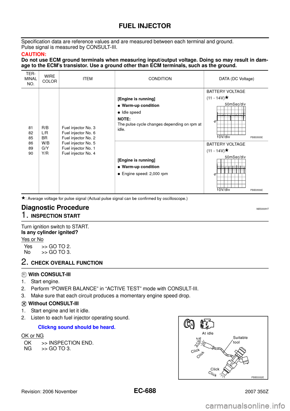
Specification data are reference values and are measured between each terminal and ground.
Pulse signal is measured by CONSULT-III.
CAUTION:
Do not use ECM ground terminals when measuring input/output voltage. Doing so may result in dam-
age to the ECM's transistor. Use a ground other than ECM terminals, such as the ground.
: Average voltage for pulse signal (Actual pulse signal can be confirmed by oscilloscope.)
Diagnostic ProcedureNBS000HT
1. INSPECTION START
Turn ignition switch to START.
Is any cylinder ignited?
Ye s o r N o
Yes >> GO TO 2.
No >> GO TO 3.
2. CHECK OVERALL FUNCTION
With CONSULT-III
1. Start engine.
2. Perform “POWER BALANCE” in “ACTIVE TEST” mode with CONSULT-III.
3. Make sure that each circuit produces a momentary engine speed drop.
Without CONSULT-III
1. Start engine and let it idle.
2. Listen to each fuel injector operating sound.
OK or NG
OK >> INSPECTION END.
NG >> GO TO 3.
TER-
MINAL
NO.WIRE
COLORITEM CONDITION DATA (DC Voltage)
81
82
85
86
89
90R/B
L/R
BR
W/B
G/Y
Y/RFuel injector No. 3
Fuel injector No. 6
Fuel injector No. 2
Fuel injector No. 5
Fuel injector No. 1
Fuel injector No. 4[Engine is running]
�Warm-up condition
�Idle speed
NOTE:
The pulse cycle changes depending on rpm at
idle.BATTERY VOLTAGE
(11 - 14V)
[Engine is running]
�Warm-up condition
�Engine speed: 2,000 rpmBATTERY VOLTAGE
(11 - 14V)
PBIB3555E
PBIB3556E
Clickng sound should be heard.
PBIB3332E