Page 677 of 720

ASCD BRAKE SWITCH
EC-677
C
D
E
F
G
H
I
J
K
L
MA
EC
Revision: 2006 November2007 350Z
6. CHECK ASCD BRAKE SWITCH
Refer to EC-680, "
Component Inspection"
OK or NG
OK >> GO TO 7.
NG >> Replace ASCD brake switch.
7. CHECK INTERMITTENT INCIDENT
Refer to EC-141, "
TROUBLE DIAGNOSIS FOR INTERMITTENT INCIDENT" .
>>INSPECTION END
M/T MODELS
1. CHECK OVERALL FUNCTION-I
With CONSULT-III
1. Turn ignition switch ON.
2. Select “BRAKE SW1” in “DATA MONITOR” mode with CONSULT-III.
3. Check “BRAKE SW1” indication under the following conditions.
Without CONSULT-III
1. Turn ignition switch ON.
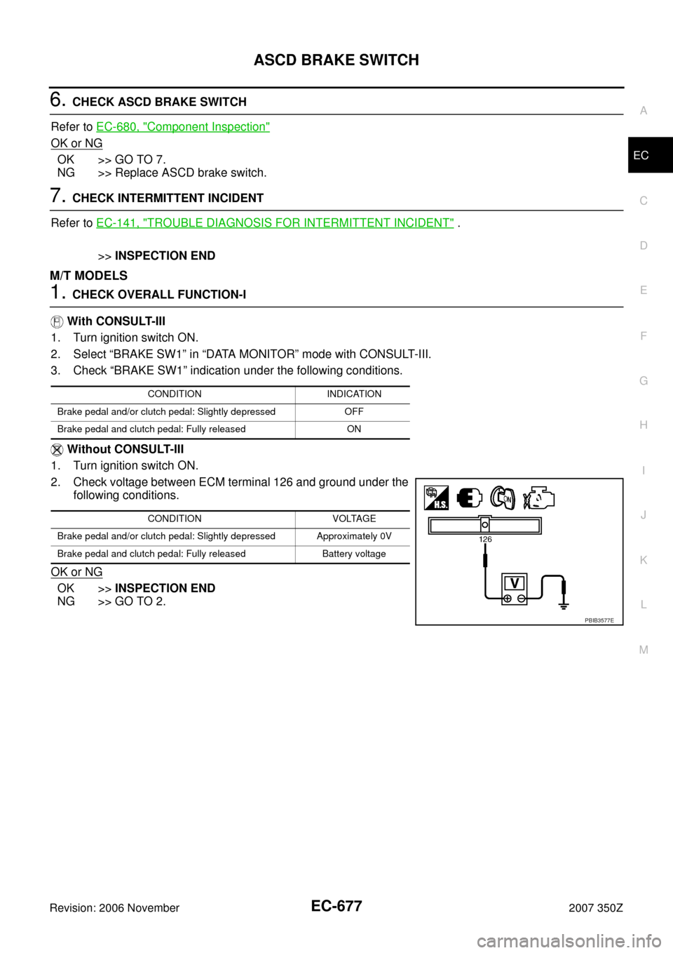
2. Check voltage between ECM terminal 126 and ground under the
following conditions.
OK or NG
OK >>INSPECTION END
NG >> GO TO 2.
CONDITION INDICATION
Brake pedal and/or clutch pedal: Slightly depressed OFF
Brake pedal and clutch pedal: Fully released ON
CONDITION VOLTAGE
Brake pedal and/or clutch pedal: Slightly depressed Approximately 0V
Brake pedal and clutch pedal: Fully released Battery voltage
PBIB3577E
Page 680 of 720

EC-680
ASCD BRAKE SWITCH
Revision: 2006 November2007 350Z
10. CHECK INTERMITTENT INCIDENT
Refer to EC-141, "
TROUBLE DIAGNOSIS FOR INTERMITTENT INCIDENT" .
>>INSPECTION END
Component InspectionNBS000ID
ASCD BRAKE SWITCH
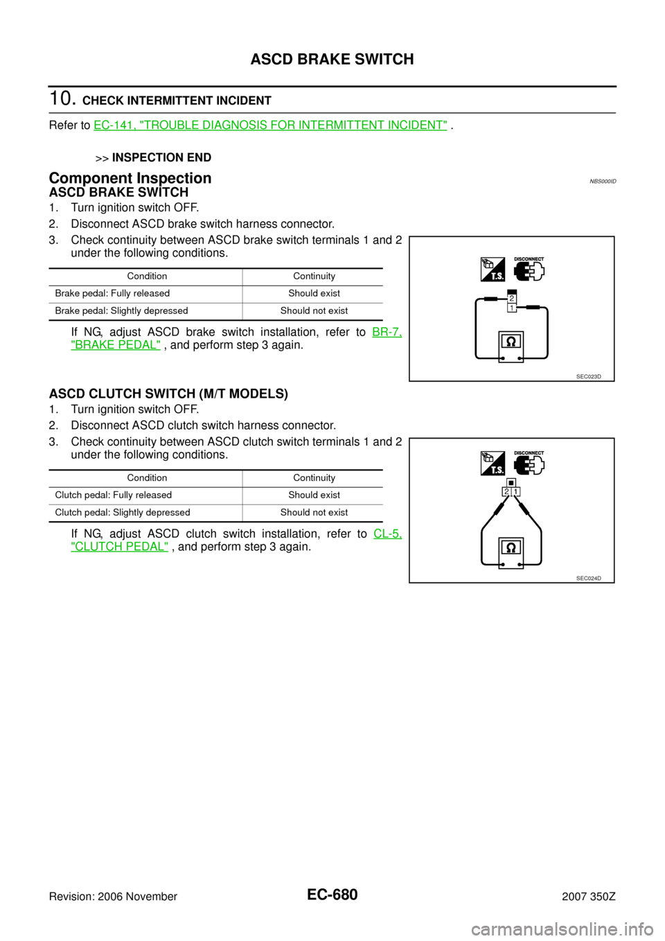
1. Turn ignition switch OFF.
2. Disconnect ASCD brake switch harness connector.
3. Check continuity between ASCD brake switch terminals 1 and 2
under the following conditions.
If NG, adjust ASCD brake switch installation, refer to BR-7,
"BRAKE PEDAL" , and perform step 3 again.
ASCD CLUTCH SWITCH (M/T MODELS)
1. Turn ignition switch OFF.
2. Disconnect ASCD clutch switch harness connector.
3. Check continuity between ASCD clutch switch terminals 1 and 2
under the following conditions.
If NG, adjust ASCD clutch switch installation, refer to CL-5,
"CLUTCH PEDAL" , and perform step 3 again.
Condition Continuity
Brake pedal: Fully released Should exist
Brake pedal: Slightly depressed Should not exist
SEC023D
Condition Continuity
Clutch pedal: Fully released Should exist
Clutch pedal: Slightly depressed Should not exist
SEC024D
Page 684 of 720

EC-684
ELECTRICAL LOAD SIGNAL
Revision: 2006 November2007 350Z
ELECTRICAL LOAD SIGNALPFP:25350
DescriptionNBS000I6
The electrical load signal (Headlamp switch signal, rear window defogger switch signal, etc.) is transferred
through the CAN communication line from BCM to ECM via IPDM E/R.
CONSULT-III Reference Value in Data Monitor ModeNBS000I7
Specification data are reference values.
Diagnostic ProcedureNBS000I8
1. CHECK LOAD SIGNAL CIRCUIT OVERALL FUNCTION-I
1. Turn ignition switch ON.
2. Connect CONSULT-III and select “DATA MONITOR” mode.
3. Select “LOAD SIGNAL” and check indication under the following conditions.
OK or NG
OK >> GO TO 2.
NG >> GO TO 4.
2. CHECK LOAD SIGNAL CIRCUIT OVERALL FUNCTION-II
Check “LOAD SIGNAL” indication under the following conditions.
OK or NG
OK >> GO TO 3.
NG >> GO TO 5.
3. CHECK HEATER FAN SIGNAL CIRCUIT OVERALL FUNCTION
With CONSULT-III
Check “HEATER FAN SW” in “DATA MONITOR” mode with CONSULT-III under the following conditions.
OK or NG
OK >>INSPECTION END
NG >> GO TO 6.
MONITOR ITEM CONDITION SPECIFICATION
LOAD SIGNAL
�Ignition switch: ONRear window defogger switch: ON and/
or lighting switch: 2nd positionON
Rear window defogger switch and light-
ing switch: OFFOFF
HEATER FAN SW
�Engine: After warming up, idle
the engineHeater fan switch: ON ON
Heater fan switch: OFF OFF
Condition Indication
Rear window defogger switch: ON ON
Rear window defogger switch: OFF OFF
Condition Indication
Lighting switch: ON at 2nd position ON
Lighting switch: OFF OFF
Condition Indication
Heater fan: Operating ON
Heater fan: Not operating OFF
Page 685 of 720
ELECTRICAL LOAD SIGNAL
EC-685
C
D
E
F
G
H
I
J
K
L
MA
EC
Revision: 2006 November2007 350Z
4. CHECK REAR WINDOW DEFOGGER SYSTEM
Refer to GW-56, "
REAR WINDOW DEFOGGER" .
>>INSPECTION END
5. CHECK HEADLAMP SYSTEM
Refer to LT- 5 , "
HEADLAMP (FOR USA)" or LT- 3 2 , "HEADLAMP (FOR CANADA) - DAYTIME LIGHT SYS-
TEM -" .
>>INSPECTION END
6. CHECK HEATER FAN CONTROL SYSTEM
Refer to AT C - 3 3 , "
TROUBLE DIAGNOSIS" .
>>INSPECTION END
Page 718 of 720

EC-718
SERVICE DATA AND SPECIFICATIONS (SDS)
Revision: 2006 November2007 350Z
SERVICE DATA AND SPECIFICATIONS (SDS)PFP:00030
Fuel PressureNBS000IJ
Idle Speed and Ignition TimingNBS000IK
*: Under the following conditions:
�Air conditioner switch: OFF
�Electric load: OFF (Lights, heater fan & rear window defogger)
�Steering wheel: Kept in straight-ahead position
Calculated Load ValueNBS000IL
Mass Air Flow SensorNBS000IM
*: Engine is warmed up to normal operating temperature and running under no load.
Intake Air Temperature SensorNBS000IN
Engine Coolant Temperature SensorNBS000IO
Air Fuel Ratio (A/F) Sensor 1 HeaterNBS000IP
Heated Oxygen sensor 2 HeaterNBS000IQ
Crankshaft Position Sensor (POS)NBS000IR
Refer to EC-393, "Component Inspection" .
Camshaft Position Sensor (PHASE)NBS000IS
Refer to EC-405, "Component Inspection" .
Fuel pressure at idling kPa (kg/cm2 , psi)Approximately 350 (3.57, 51)
Target idle speedA/T No load* (in P or N position)
650 ± 50 rpm
M/T No load* (in Neutral position)
Air conditioner: ONA/T In P or N position 650 rpm or more
M/T In Neutral position 800 rpm or more
Ignition timingA/T In P or N position
15° ± 5° BTDC
M/T In Neutral position
Conditions Calculated load value % (Using CONSULT-III or GST)
At idle5 - 35
At 2,500 rpm5 - 35
Supply voltageBattery voltage (11 - 14V)
Output voltage at idle0.8 - 1.1V*
Mass air flow (Using CONSULT-III or GST)2.0 - 6.0 g·m/sec at idle*
7.0 - 20.0 g·m/sec at 2,500 rpm*
Temperature °C (°F) Resistance kΩ
25 (77)1.800 - 2.200
Temperature °C (°F) Resistance kΩ
20 (68)2.37 - 2.63
50 (122)0.68 - 1.00
90 (194)0.236 - 0.260
Resistance [at 25°C (77°F)] 1.8 - 2.44Ω
Resistance [at 25°C (77°F)] 3.4 - 4.4Ω