Page 77 of 260
REMOTE KEYLESS ENTRY SYSTEM
BL-77
C
D
E
F
G
H
J
K
L
MA
B
BL
Revision: 2006 November2007 350Z
Check Key Fob Battery and Function NIS0001K
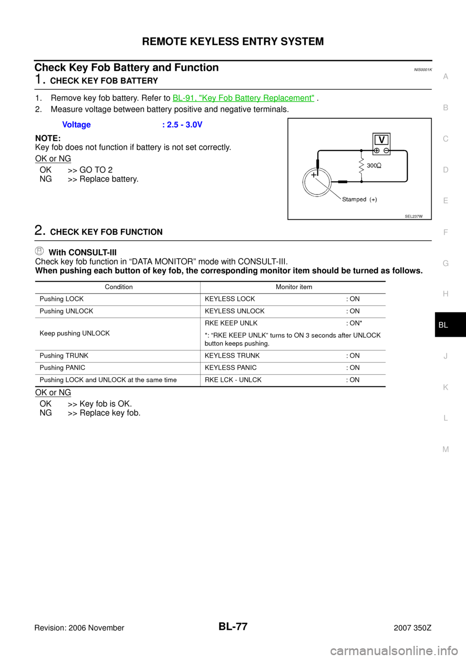
1. CHECK KEY FOB BATTERY
1. Remove key fob battery. Refer to BL-91, "
Key Fob Battery Replacement" .
2. Measure voltage between battery positive and negative terminals.
NOTE:
Key fob does not function if battery is not set correctly.
OK or NG
OK >> GO TO 2
NG >> Replace battery.
2. CHECK KEY FOB FUNCTION
With CONSULT-III
Check key fob function in “DATA MONITOR” mode with CONSULT-III.
When pushing each button of key fob, the corresponding monitor item should be turned as follows.
OK or NG
OK >> Key fob is OK.
NG >> Replace key fob.Voltage : 2.5 - 3.0V
SEL237W
Condition Monitor item
Pushing LOCK KEYLESS LOCK : ON
Pushing UNLOCK KEYLESS UNLOCK : ON
Keep pushing UNLOCKRKE KEEP UNLK : ON*
*: “RKE KEEP UNLK” turns to ON 3 seconds after UNLOCK
button keeps pushing.
Pushing TRUNK KEYLESS TRUNK : ON
Pushing PANIC KEYLESS PANIC : ON
Pushing LOCK and UNLOCK at the same time RKE LCK - UNLCK : ON
Page 78 of 260
BL-78
REMOTE KEYLESS ENTRY SYSTEM
Revision: 2006 November2007 350Z
Check ACC Switch NIS0001L
1. CHECK ACC SWITCH
With CONSULT-III
Check ACC switch (“ACC ON SW”) in “DATA MONITOR” mode with CONSULT-III.
Without CONSULT-III
Check voltage between BCM connector and ground.
OK or NG
OK >> ACC switch is OK.
NG >> Check the following.
�10A fuse [No. 6, located in fuse block (J/B)]
�Harness for open or short between BCM and fuse
Monitor item Condition
ACC ON SWIgnition switch position is ACC or ON : ON
Ignition switch position is OFF : OFF
ItemCon-
nectorTerminals
(Wire color)
ConditionVoltage [V]
(Approx.)
(+) (–)
Ignition switch M90 11 (LG) GroundACC or ON Battery voltage
OFF 0
PIIA7002E
Page 81 of 260
REMOTE KEYLESS ENTRY SYSTEM
BL-81
C
D
E
F
G
H
J
K
L
MA
B
BL
Revision: 2006 November2007 350Z
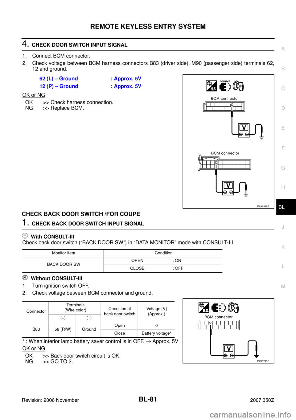
4. CHECK DOOR SWITCH INPUT SIGNAL
1. Connect BCM connector.
2. Check voltage between BCM harness connectors B83 (driver side), M90 (passenger side) terminals 62,
12 and ground.
OK or NG
OK >> Check harness connection.
NG >> Replace BCM.
CHECK BACK DOOR SWITCH /FOR COUPE
1. CHECK BACK DOOR SWITCH INPUT SIGNAL
With CONSULT-III
Check back door switch (“BACK DOOR SW”) in “DATA MONITOR” mode with CONSULT-III.
Without CONSULT-III
1. Turn ignition switch OFF.
2. Check voltage between BCM connector and ground.
* : When interior lamp battery saver control is in OFF. → Approx. 5V
OK or NG
OK >> Back door switch circuit is OK.
NG >> GO TO 2.62 (L) – Ground : Approx. 5V
12 (P) – Ground : Approx. 5V
PIIA9539E
Monitor item Condition
BACK DOOR SWOPEN : ON
CLOSE : OFF
ConnectorTerminals
(Wire color)Condition of
back door switchVoltage [V]
(Approx.)
(+) (–)
B83 58 (R/W) GroundOpen 0
Close Battery voltage*
PIIB3793E
Page 83 of 260
REMOTE KEYLESS ENTRY SYSTEM
BL-83
C
D
E
F
G
H
J
K
L
MA
B
BL
Revision: 2006 November2007 350Z
Check Trunk Lid Lock Assembly (Trunk Room Lamp Switch) / For RoadsterNIS0001N
1. CHECK TRUNK LID LOCK ASSEMBLY (TRUNK ROOM LAMP SWITCH) INPUT SIGNAL
With CONSULT-III
Check trunk lid opener switch (“TRUNK OPN MNTR”) in “DATA MONITOR” mode with CONSULT-III.
Without CONSULT-III
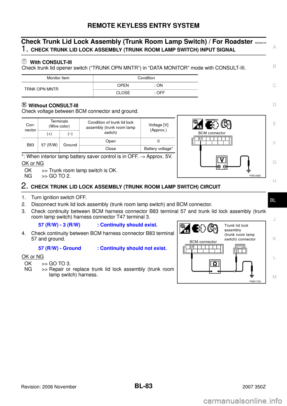
Check voltage between BCM connector and ground.
*: When interior lamp battery saver control is in OFF. → Approx. 5V.
OK or NG
OK >> Trunk room lamp switch is OK.
NG >> GO TO 2.
2. CHECK TRUNK LID LOCK ASSEMBLY (TRUNK ROOM LAMP SWITCH) CIRCUIT
1. Turn ignition switch OFF.
2. Disconnect trunk lid lock assembly (trunk room lamp switch) and BCM connector.
3. Check continuity between BCM harness connector B83 terminal 57 and trunk lid lock assembly (trunk
room lamp switch) harness connector T47 terminal 3.
4. Check continuity between BCM harness connector B83 terminal
57 and ground.
OK or NG
OK >> GO TO 3.
NG >> Repair or replace trunk lid lock assembly (trunk room
lamp switch) harness.
Monitor item Condition
TRNK OPN MNTROPEN : ON
CLOSE : OFF
Con-
nectorTe r m i n a l s
(Wire color)Condition of trunk lid lock
assembly (trunk room lamp
switch)Voltage [V]
(Approx.)
(+) (–)
B83 57 (R/W) GroundOpen 0
Close Battery voltage*
PIIB1266E
57 (R/W) - 3 (R/W) : Continuity should exist.
57 (R/W) - Ground : Continuity should not exist.
PIIB9170E
Page 85 of 260
REMOTE KEYLESS ENTRY SYSTEM
BL-85
C
D
E
F
G
H
J
K
L
MA
B
BL
Revision: 2006 November2007 350Z
Check IPDM E/R Operation NIS0001P
1. CHECK IPDM E/R INPUT SIGNAL
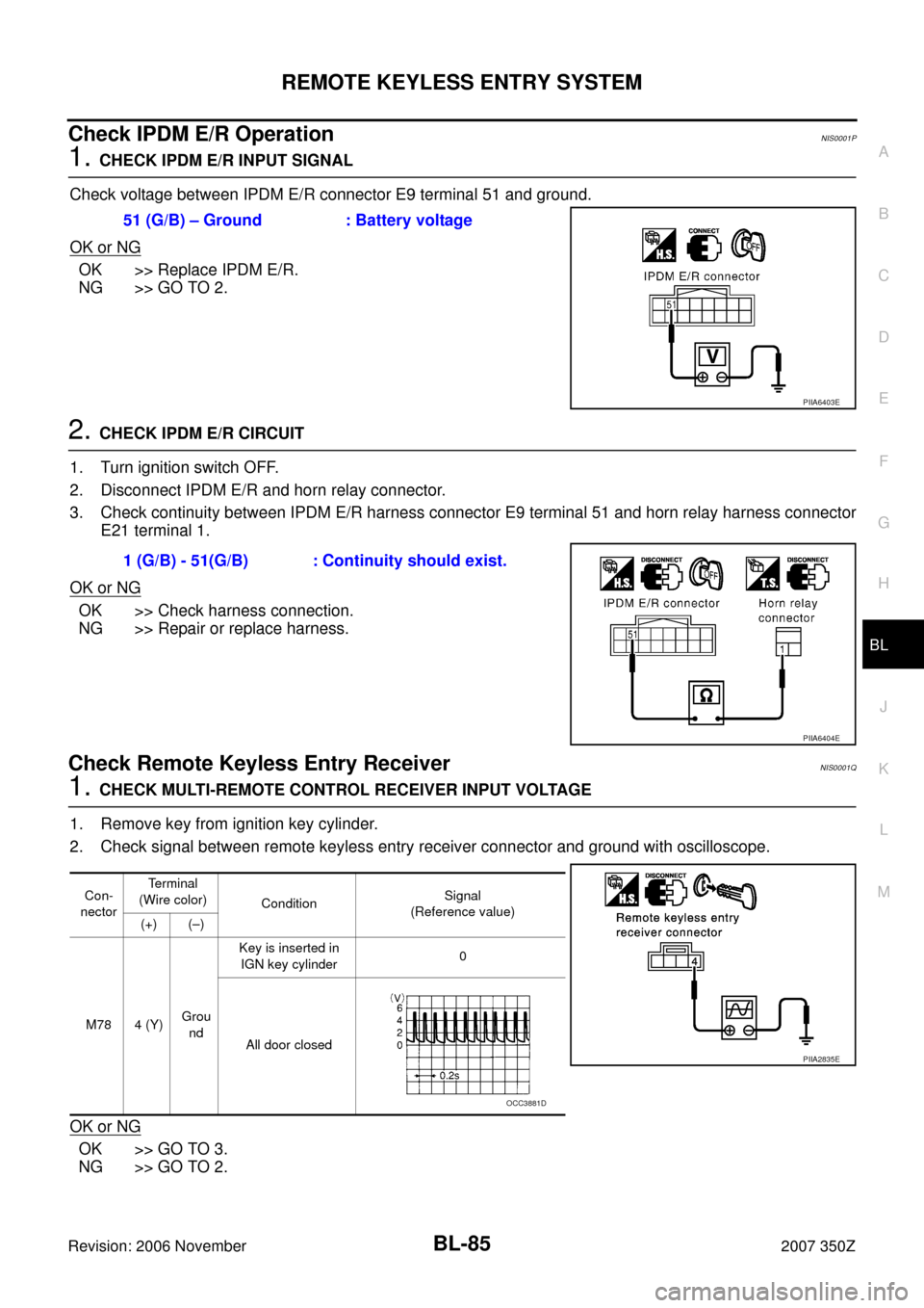
Check voltage between IPDM E/R connector E9 terminal 51 and ground.
OK or NG
OK >> Replace IPDM E/R.
NG >> GO TO 2.
2. CHECK IPDM E/R CIRCUIT
1. Turn ignition switch OFF.
2. Disconnect IPDM E/R and horn relay connector.
3. Check continuity between IPDM E/R harness connector E9 terminal 51 and horn relay harness connector
E21 terminal 1.
OK or NG
OK >> Check harness connection.
NG >> Repair or replace harness.
Check Remote Keyless Entry Receiver NIS0001Q
1. CHECK MULTI-REMOTE CONTROL RECEIVER INPUT VOLTAGE
1. Remove key from ignition key cylinder.
2. Check signal between remote keyless entry receiver connector and ground with oscilloscope.
OK or NG
OK >> GO TO 3.
NG >> GO TO 2.51 (G/B) – Ground : Battery voltage
PIIA6403E
1 (G/B) - 51(G/B) : Continuity should exist.
PIIA6404E
Con-
nectorTerminal
(Wire color)
Condition Signal
(Reference value)
(+) (–)
M78 4 (Y)Grou
ndKey is inserted in
IGN key cylinder 0
All door closed
PIIA2835E
OCC3881D
Page 91 of 260
REMOTE KEYLESS ENTRY SYSTEM
BL-91
C
D
E
F
G
H
J
K
L
MA
B
BL
Revision: 2006 November2007 350Z
NOTE:
�If a key fob is lost, the ID code of the lost key fob must be erased to prevent unauthorized use. A specific
ID code can be erased with CONSULT-III. However, when the ID code of a lost key fob is not known, all
controller ID codes should be erased. After all ID codes are erased, the ID codes of all remaining and/or
new key fobs must be re-registered.
To erase all ID codes in memory, register one ID code (key fob) five times. After all ID codes are erased,
the ID codes of all remaining and/or new key fobs must be re-registered.
�When registering an additional key fob, the existing ID codes in memory may or may not be erased. If five
ID codes are stored in memory, when an additional code is registered, only the oldest code is erased. If
less than five ID codes are stored in memory, when an additional ID code is registered, the new ID code is
added and no ID codes are erased.
�If you need to activate more than two additional new key fobs, repeat the procedure “Additional ID code
entry” for each new key fob.
�Entry of maximum five ID codes is allowed. When more than five ID codes are entered, the oldest ID code
will be erased.
�Even if same ID code that is already in the memory is input, the same ID code can be entered. The code
is counted as an additional code.
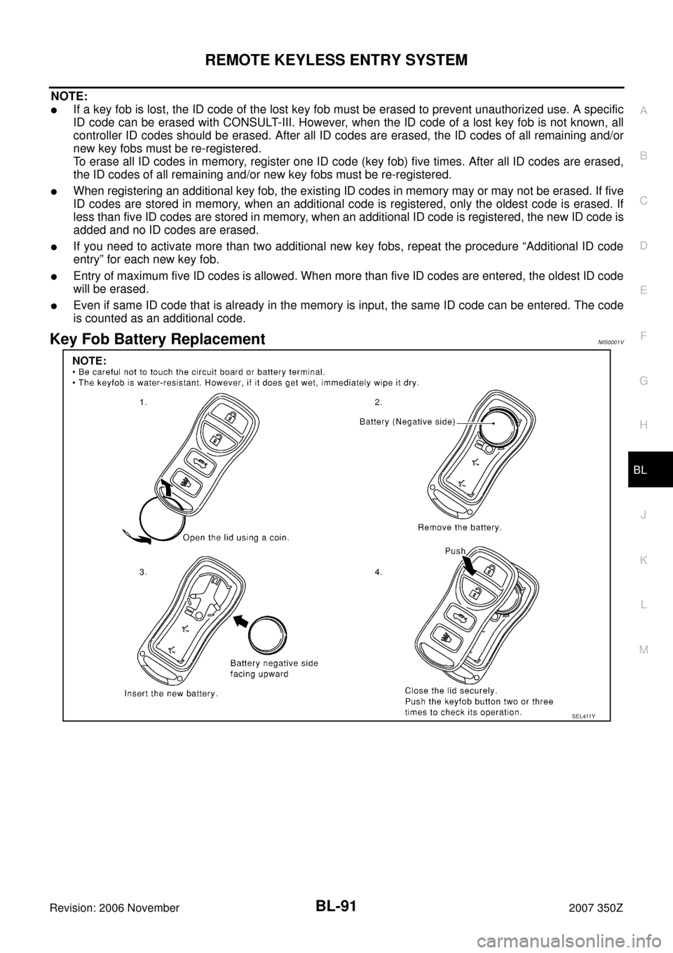
Key Fob Battery ReplacementNIS0001V
SEL411Y
Page 118 of 260
BL-118
TRUNK LID OPENER
Revision: 2006 November2007 350Z
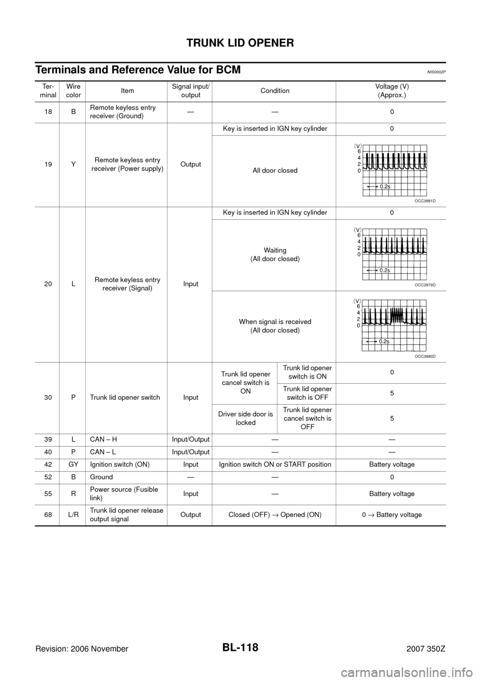
Terminals and Reference Value for BCMNIS0002P
Te r -
minalWire
colorItemSignal input/
outputConditionVoltage (V)
(Approx.)
18 BRemote keyless entry
receiver (Ground)—— 0
19 YRemote keyless entry
receiver (Power supply)OutputKey is inserted in IGN key cylinder 0
All door closed
20 LRemote keyless entry
receiver (Signal)InputKey is inserted in IGN key cylinder 0
Waiting
(All door closed)
When signal is received
(All door closed)
30 P Trunk lid opener switch InputTrunk lid opener
cancel switch is
ONTrunk lid opener
switch is ON0
Trunk lid opener
switch is OFF5
Driver side door is
lockedTrunk lid opener
cancel switch is
OFF5
39 L CAN – H Input/Output — —
40 P CAN – L Input/Output — —
42 GY Ignition switch (ON) Input Ignition switch ON or START position Battery voltage
52 B Ground — — 0
55 RPower source (Fusible
link)Input — Battery voltage
68 L/RTrunk lid opener release
output signalOutput Closed (OFF) → Opened (ON) 0 → Battery voltage
OCC3881D
OCC3879D
OCC3880D
Page 120 of 260
BL-120
TRUNK LID OPENER
Revision: 2006 November2007 350Z
Trouble DiagnosisNIS0002R
TRUNK DOSE NOT OPEN WITH TRUNK LID OPENER SWITCH
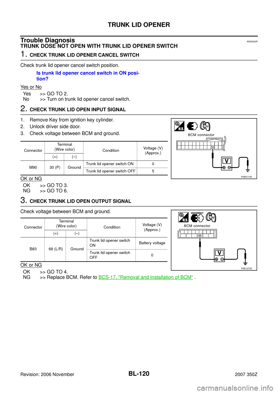
1. CHECK TRUNK LID OPENER CANCEL SWITCH
Check trunk lid opener cancel switch position.
Ye s o r N o
Yes >> GO TO 2.
No >> Turn on trunk lid opener cancel switch.
2. CHECK TRUNK LID OPEN INPUT SIGNAL
1. Remove Key from ignition key cylinder.
2. Unlock driver side door.
3. Check voltage between BCM and ground.
OK or NG
OK >> GO TO 3.
NG >> GO TO 6.
3. CHECK TRUNK LID OPEN OUTPUT SIGNAL
Check voltage between BCM and ground.
OK or NG
OK >> GO TO 4.
NG >> Replace BCM. Refer to BCS-17, "
Removal and Installation of BCM" . Is trunk lid opener cancel switch in ON posi-
tion?
ConnectorTerminal
(Wire color)
ConditionVoltage (V)
(Approx.)
(+) (–)
M90 30 (P) GroundTrunk lid opener switch ON 0
Trunk lid opener switch OFF 5
PIIB9174E
ConnectorTerminal
(Wire color)
ConditionVoltage (V)
(Approx.)
(+) (–)
B83 68 (L/R) GroundTrunk lid opener switch
ONBattery voltage
Trunk lid opener switch
OFF0
PIIB1270E