Page 235 of 312

ON-VEHICLE SERVICE
AT-235
D
E
F
G
H
I
J
K
L
MA
B
AT
Revision: 2006 November2007 350Z
Revolution SensorNCS00095
COMPONENTS
REMOVAL
1. Disconnect the battery cable from the negative terminal.
2. Drain ATF through drain hole.
3. Remove exhaust front tube and center muffler with power tool. Refer to EX-3, "
Removal and Installation" .
4. Remove rear propeller shaft. Refer to PR-6, "
Removal and Installation" .
CAUTION:
Do not impact or damage propeller shaft tube.
5. Remove control rod. Refer to AT- 2 0 5 , "
Control Rod Removal and Installation" .
6. Remove exhaust mounting bracket. Refer to EX-3, "
Removal and Installation" .
1. Rear extension 2. A/T 3. Bracket
4. Oil pan gasket 5. Clip 6. Oil pan mounting bolt
7. Oil pan 8. Drain plug 9. Drain plug gasket
10. Revolution sensor 11. Self-sealing bolt
Refer to GI section to make sure icons (symbol marks) in the figure. Refer to GI-11, "
Components" .
However, refer to the following for others.
*: Apply Genuine Anaerobic Liquid Gasket or equivalent. Refer to GI-45, "Recommended Chemical Products and Sealants" .
SCIA8271E
Page 240 of 312
AT-240
ON-VEHICLE SERVICE
Revision: 2006 November2007 350Z
10. Install bracket (2) from transmission assembly. Refer to AT- 2 1 5 ,
"COMPONENTS" .
�: Vehicle front
�: Bolt
11. Install heated oxygen sensor 2 harness (B) from clips (1).
12. Connect heated oxygen sensor 2 harness connectors (A).
13. Install exhaust mounting bracket. Refer to EX-3, "
Removal and
Installation" .
14. Install control rod. Refer to AT- 2 0 5 , "
Control Rod Removal and
Installation" .
15. Install rear propeller shaft. Refer to PR-6, "
Removal and Installation" .
CAUTION:
Do not impact or damage propeller shaft tube.
16. Install exhaust front tube and center muffler. Refer to EX-3, "
Removal and Installation" .
17. Pour ATF into A/T assembly. Refer to AT- 1 2 , "
Changing A/T Fluid" .
18. Connect the battery cable to the negative terminal.
SCIA8269E
Page 242 of 312
AT-242
TRANSMISSION ASSEMBLY
Revision: 2006 November2007 350Z
TRANSMISSION ASSEMBLYPFP:31020
Removal and InstallationNCS00097
REMOVAL
CAUTION:
�When removing A/T assembly from engine assembly, first remove crankshaft position sensor
(POS) from A/T assembly.
�Be careful not to damage sensor edge.
1. Disconnect the battery cable from the negative terminal.
2. Remove tower bar with power tool. Refer to FSU-20, "
Removal and Installation" .
3. Remove engine under covers with power tool.
4. Remove exhaust mounting bracket. Refer to EX-3, "
Removal and Installation" .
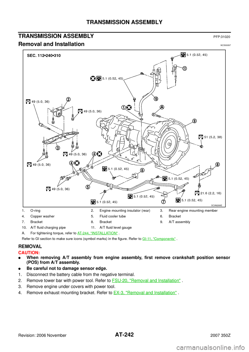
1. O-ring 2. Engine mounting insulator (rear) 3. Rear engine mounting member
4. Copper washer 5. Fluid cooler tube 6. Bracket
7. Bracket 8. Bracket 9. A/T assembly
10. A/T fluid charging pipe 11. A/T fluid level gauge
A. For tightening torque, refer to AT- 2 4 4 , "
INSTALLATION" .
Refer to GI section to make sure icons (symbol marks) in the figure. Refer to GI-11, "
Components" .
SCIA8266E
Page:
< prev 1-8 9-16 17-24