Page 242 of 312
AT-242
TRANSMISSION ASSEMBLY
Revision: 2006 November2007 350Z
TRANSMISSION ASSEMBLYPFP:31020
Removal and InstallationNCS00097
REMOVAL
CAUTION:
�When removing A/T assembly from engine assembly, first remove crankshaft position sensor
(POS) from A/T assembly.
�Be careful not to damage sensor edge.
1. Disconnect the battery cable from the negative terminal.
2. Remove tower bar with power tool. Refer to FSU-20, "
Removal and Installation" .
3. Remove engine under covers with power tool.
4. Remove exhaust mounting bracket. Refer to EX-3, "
Removal and Installation" .
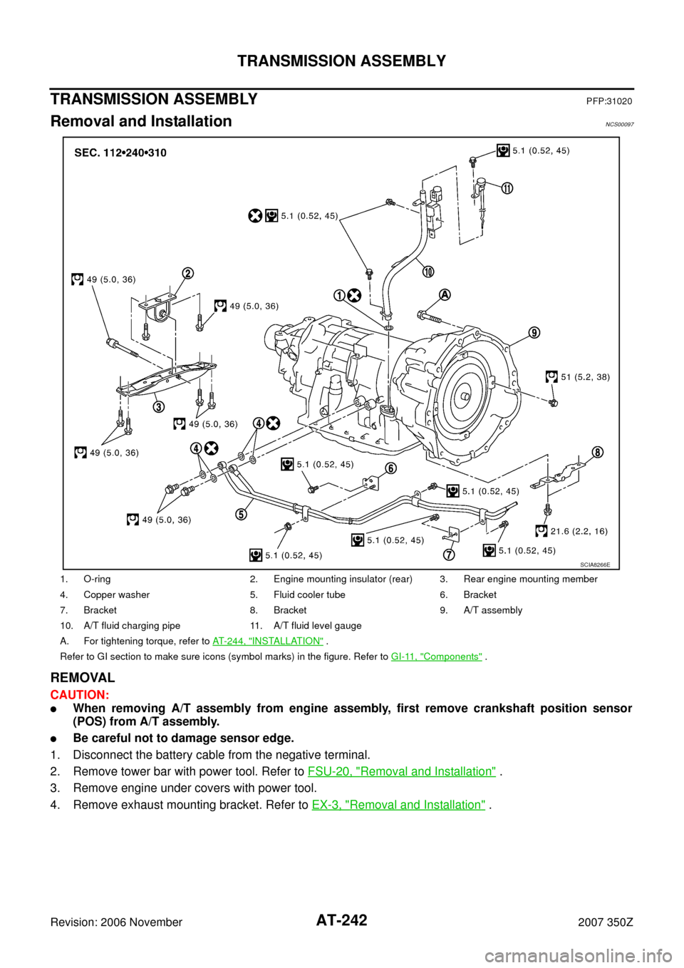
1. O-ring 2. Engine mounting insulator (rear) 3. Rear engine mounting member
4. Copper washer 5. Fluid cooler tube 6. Bracket
7. Bracket 8. Bracket 9. A/T assembly
10. A/T fluid charging pipe 11. A/T fluid level gauge
A. For tightening torque, refer to AT- 2 4 4 , "
INSTALLATION" .
Refer to GI section to make sure icons (symbol marks) in the figure. Refer to GI-11, "
Components" .
SCIA8266E
Page 243 of 312
.
�: Vehicle front
�: Bolt
6. Remove heated oxygen se")
TRANSMISSION ASSEMBLY
AT-243
D
E
F
G
H
I
J
K
L
MA
B
AT
Revision: 2006 November2007 350Z
5. Disconnect heated oxygen sensor 2 harness connectors (A).
�: Vehicle front
�: Bolt
6. Remove heated oxygen sensor 2 harness (B) from clips (1).
7. Remove bracket (2) from transmission assembly.
8. Remove front cross bar with power tool. Refer to FSU-8, "
Com-
ponents" .
9. Remove exhaust front tube and center muffler with power tool.
Refer to EX-3, "
Removal and Installation" .
10. Remove three way catalyst (right bank) and three way catalyst
(left bank). Refer to EM-22, "
Removal and Installation" .
11. Remove crankshaft position sensor (POS) (1). Refer to EM-26,
"Removal and Installation" .
�Three way catalyst (right bank) (2)
CAUTION:
�Do not subject it to impact by dropping or hitting it.
�Do not disassemble.
�Do not allow metal filings, etc. to get on the sensor's front
edge magnetic area.
�Do not place in an area affected by magnetism.
12. Remove rear propeller shaft. Refer to PR-6, "
Removal and
Installation" .
CAUTION:
Do not impact, or damage propeller shaft tube.
13. Remove control rod. Refer to AT- 2 0 5 , "
Control Rod Removal and Installation" .
14. Disconnect the following:
�A/T assembly harness connector
�S terminal connector (A)
�EPS solenoid valve harness connector (B)
15. Remove starter motor with power tool. Refer to SC-17,
"Removal and Installation" .
16. Remove A/T fluid level gauge.
17. Remove A/T fluid charging pipe
18. Remove O-ring from A/T fluid charging pipe.
19. Remove fluid cooler tube according to the following procedure.
a. Remove mounting nuts of the engine mounting insulator (LH) and engine mounting insulator (RH) on the
undersurface of the vehicle. Refer to EM-101, "
Removal and Installation" .
b. Push engine assembly upward from the vehicle with transmission jack to create clearance for removing
fluid cooler tube.
CAUTION:
Be careful with hoses and harness when pushing up the engine assembly.
c. Remove fluid cooler tube.
20. Plug up openings such as A/T fluid charging pipe hole, etc.
21. Remove rear plate cover from converter housing. Refer to EM-26, "
Removal and Installation" .
22. Turn crankshaft, and remove the four tightening bolts for drive plate and torque converter.
CAUTION:
When turning crankshaft, turn it clockwise as viewed from the front of the engine.
23. Support A/T assembly with a transmission jack.
CAUTION:
When setting the transmission jack, be careful not to allow it to collide against the drain plug.
24. Remove rear engine mounting member with power tool. Refer to AT- 2 4 2 , "
Removal and Installation" .
SCIA8269E
SCIA8272E
SCIA8273E
Page 244 of 312
 with power tool. Refer to AT- 2 4 2 , \"Removal and Installation\" .
26. Remove bolts fixing A/")
AT-244
TRANSMISSION ASSEMBLY
Revision: 2006 November2007 350Z
25. Remove engine mounting insulator (rear) with power tool. Refer to AT- 2 4 2 , "Removal and Installation" .
26. Remove bolts fixing A/T assembly to engine assembly with power tool.
27. Remove A/T assembly from vehicle with a transmission jack.
�Secure torque converter to prevent it from dropping.
�Secure A/T assembly to a transmission jack.
28. Remove air breather hose. Refer to AT- 2 4 1 , "
Removal and
Installation" .
INSPECTION
Installation and Inspection of Torque Converter
�After inserting a torque converter to a A/T, be sure to check dis-
tance “A” to ensure it is within the reference value limit.
INSTALLATION
Install the removed parts in the reverse order of the removal, while paying attention to the following work.
�When installing A/T assembly to the engine assembly, attach the
fixing bolts in accordance with the following standard.
–: Engine to transmission
–: Transmission to engine
�Align the positions of tightening bolts for drive plate with those of
the torque converter, and temporarily tighten the bolts. Then
tighten the bolts with the specified torque.
CAUTION:
�When turning crankshaft, turn it clockwise as viewed from
the front of the engine.
�When tightening the tightening bolts for torque converter
after fixing crankshaft pulley bolts, be sure to confirm the
tightening torque of crankshaft pulley mounting bolts.
Refer to EM-53, "
TIMING CHAIN" .
�After converter is installed to drive plate, rotate crankshaft several turns and check to be sure that
transmission rotates freely without binding.
�Install crankshaft position sensor (POS). Refer to EM-26, "Removal and Installation" .
SCIA0499E
Distance “A”: 25.0 mm (0.98 in) or more
SCIA5694E
Bolt symbol A B
Number of bolts 8 4
Bolt length mm (in) 65 (2.56) 35 (1.38)
Tightening torque
N·m (kg-m, ft-lb)75 (7.7, 55) 46.6 (4.8, 34)
SCIA8152E
: 51 N·m (5.2 kg-m, 38 ft-lb)
SCIA1493E
Page 245 of 312
TRANSMISSION ASSEMBLY
AT-245
D
E
F
G
H
I
J
K
L
MA
B
AT
Revision: 2006 November2007 350Z
�After completing installation, check A/T fluid leakage, A/T fluid level and A/T position. Refer to AT- 1 2 ,
"Checking A/T Fluid" , AT- 2 0 6 , "Checking of A/T Position" .
Page 251 of 312
OVERHAUL
AT-251
D
E
F
G
H
I
J
K
L
MA
B
AT
Revision: 2006 November2007 350Z
10. Revolution sensor 11. Parking gear 12. Output shaft
13. Bearing race 14. Needle bearing 15. Manual plate
16. Parking rod 17. Manual shaft oil seal 18. Manual shaft
19. O-ring 20. Band servo anchor end pin 21. Detent spring
22. Spacer 23. Seal ring 24. Snap ring
25. Return spring 26. O-ring 27. Servo assembly
28. Snap ring 29. Sub-harness 30. Control valve with TCM
31. Bracket 32. A/T fluid temperature sensor 2 33. Clip
34. Oil pan mounting bolt 35. Oil pan 36. Magnet
37. Drain plug 38. Drain plug gasket 39. Oil pan gasket
40. Terminal cord assembly 41. O-ring 42. Retaining pin
43. Transmission case
Refer to GI section to make sure icons (symbol marks) in the figure. Refer to GI-11, "
Components" .
However, refer to the following for others.
*: Apply Genuine Anaerobic Liquid Gasket or equivalent. Refer to GI-45, "Recommended Chemical Products and Sealants" .
Page 255 of 312
DISASSEMBLY
AT-255
D
E
F
G
H
I
J
K
L
MA
B
AT
Revision: 2006 November2007 350Z
DISASSEMBLYPFP:31020
DisassemblyNCS0009B
CAUTION:
Do not disassemble parts behind Drum Support. Refer to AT- 1 7 , "
Cross-sectional View" .
1. Drain ATF through drain hole.
2. Remove torque converter by holding it firmly and turing while
pulling straight out.
3. Check torque converter one-way clutch using check tool as
shown at figure.
a. Insert check tool into the groove of bearing support built into
one-way clutch outer race.
b. When fixing bearing support with check tool, rotate one- way
clutch spline using screwdriver.
c. Check that inner race rotates clockwise only. If not, replace
torque converter assembly.
4. Remove tightening bolts ( ) for converter housing and trans-
mission case.
5. Remove converter housing from transmission case.
CAUTION:
Be careful not to scratch converter housing.
SCIA5010E
SCIA3171E
SCIA8096E
Page 256 of 312
AT-256
DISASSEMBLY
Revision: 2006 November2007 350Z
6. Remove O-ring from input clutch assembly.
7. Remove tightening bolts for oil pump assembly and transmis-
sion case.
8. Attach the sliding hammers to oil pump assembly and extract it
evenly from transmission case.
CAUTION:
�Fully tighten sliding hammer screw.
�Make sure that bearing race is installed to the oil pump
assembly edge surface.
9. Remove O-ring from oil pump assembly.
SCIA5011E
SCIA2300E
SCIA5312E
SCIA5172E
Page 258 of 312
AT-258
DISASSEMBLY
Revision: 2006 November2007 350Z
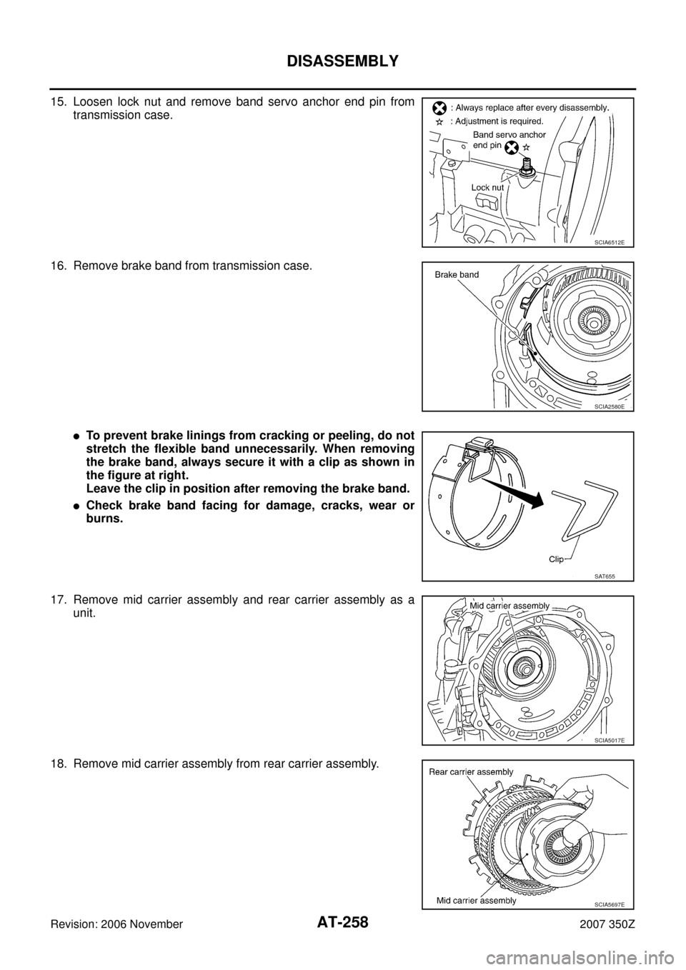
15. Loosen lock nut and remove band servo anchor end pin from
transmission case.
16. Remove brake band from transmission case.
�To prevent brake linings from cracking or peeling, do not
stretch the flexible band unnecessarily. When removing
the brake band, always secure it with a clip as shown in
the figure at right.
Leave the clip in position after removing the brake band.
�Check brake band facing for damage, cracks, wear or
burns.
17. Remove mid carrier assembly and rear carrier assembly as a
unit.
18. Remove mid carrier assembly from rear carrier assembly.
SCIA6512E
SCIA2580E
SAT655
SCIA5017E
SCIA5697E