Page 89 of 142
TROUBLE DIAGNOSIS
ATC-89
C
D
E
F
G
H
I
K
L
MA
B
AT C
Revision: 2006 November2007 350Z
Insufficient HeatingNJS00017
SYMPTOM: Insufficient heating
INSPECTION FLOW
*1AT C - 5 3 , "Operational Check"*2ATC-46, "FUNCTION CONFIRMA-
TION PROCEDURE", see No. 1.*3ATC-46, "
FUNCTION CONFIRMA-
TION PROCEDURE", see No. 5 to 7.
*4AT C - 6 3 , "
Air Mix Door Motor Cir-
cuit"
*5ATC-46, "FUNCTION CONFIRMA-
TION PROCEDURE", see No. 9.*6ATC-56, "
LAN System Circuit"
*7AT C - 6 9 , "Blower Motor Circuit"*8ATC-63, "Air Mix Door Motor Circuit"*9EC-223, "DTC P0117, P0118 ECT
SENSOR"
*10CO-10, "Changing Engine Coolant"*11CO-15, "Checking Radiator Cap"
SJIA1131E
Page 113 of 142

HEATER & COOLING UNIT ASSEMBLY
ATC-113
C
D
E
F
G
H
I
K
L
MA
B
AT C
Revision: 2006 November2007 350Z
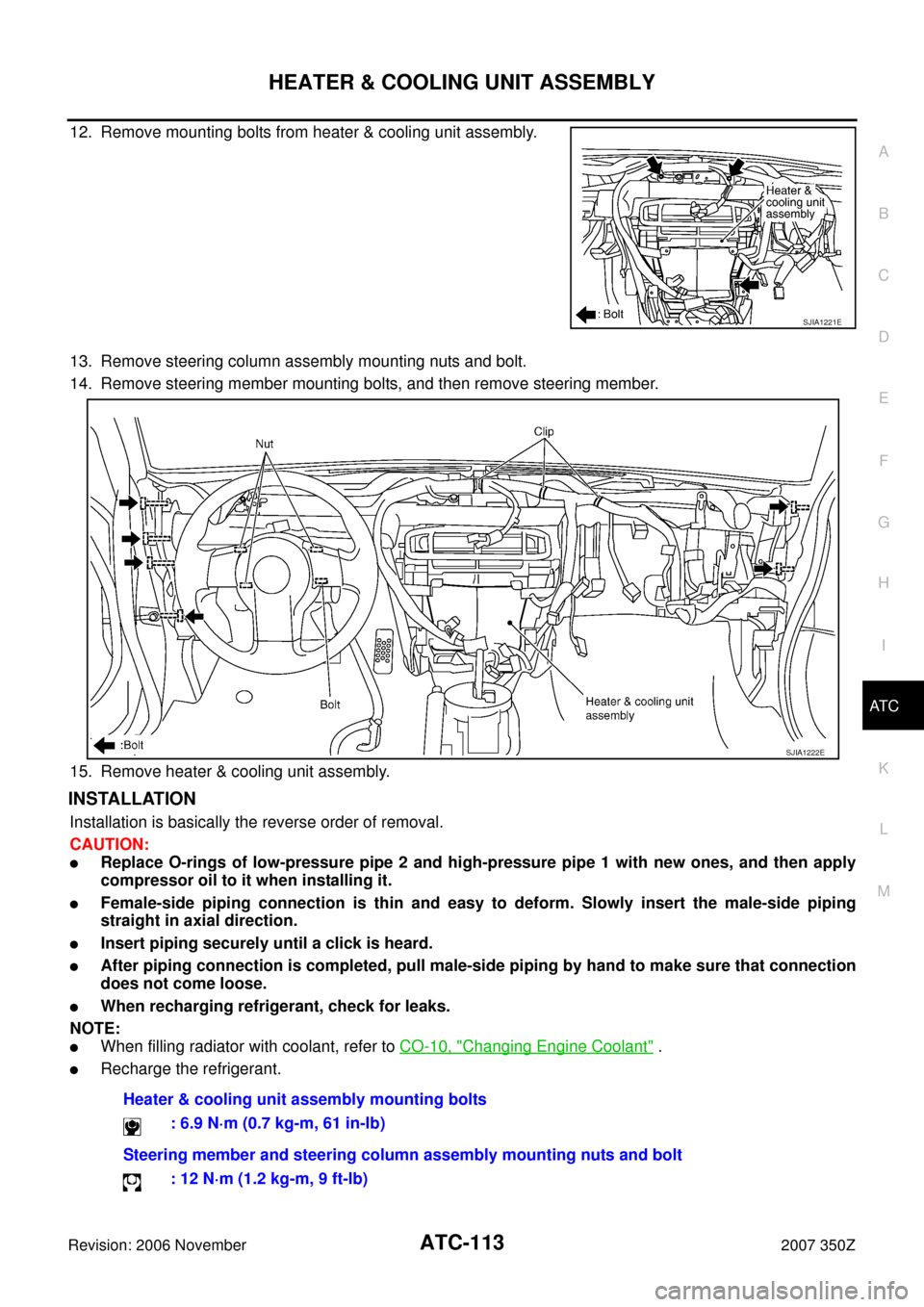
12. Remove mounting bolts from heater & cooling unit assembly.
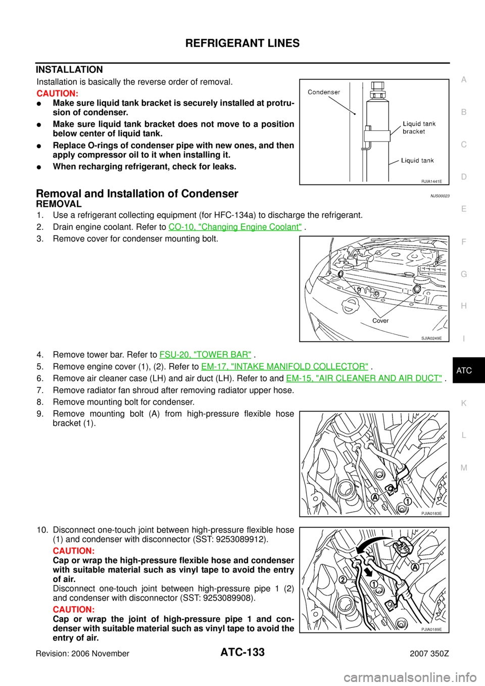
13. Remove steering column assembly mounting nuts and bolt.
14. Remove steering member mounting bolts, and then remove steering member.
15. Remove heater & cooling unit assembly.
INSTALLATION
Installation is basically the reverse order of removal.
CAUTION:
�Replace O-rings of low-pressure pipe 2 and high-pressure pipe 1 with new ones, and then apply
compressor oil to it when installing it.
�Female-side piping connection is thin and easy to deform. Slowly insert the male-side piping
straight in axial direction.
�Insert piping securely until a click is heard.
�After piping connection is completed, pull male-side piping by hand to make sure that connection
does not come loose.
�When recharging refrigerant, check for leaks.
NOTE:
�When filling radiator with coolant, refer to CO-10, "Changing Engine Coolant" .
�Recharge the refrigerant.
SJIA1221E
SJIA1222E
Heater & cooling unit assembly mounting bolts
: 6.9 N·m (0.7 kg-m, 61 in-lb)
Steering member and steering column assembly mounting nuts and bolt
: 12 N·m (1.2 kg-m, 9 ft-lb)
Page 133 of 142

REFRIGERANT LINES
ATC-133
C
D
E
F
G
H
I
K
L
MA
B
AT C
Revision: 2006 November2007 350Z
INSTALLATION
Installation is basically the reverse order of removal.
CAUTION:
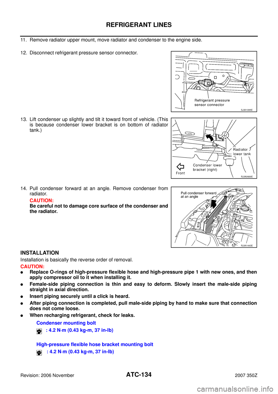
�Make sure liquid tank bracket is securely installed at protru-
sion of condenser.
�Make sure liquid tank bracket does not move to a position
below center of liquid tank.
�Replace O-rings of condenser pipe with new ones, and then
apply compressor oil to it when installing it.
�When recharging refrigerant, check for leaks.
Removal and Installation of CondenserNJS00023
REMOVAL
1. Use a refrigerant collecting equipment (for HFC-134a) to discharge the refrigerant.
2. Drain engine coolant. Refer to CO-10, "
Changing Engine Coolant" .
3. Remove cover for condenser mounting bolt.
4. Remove tower bar. Refer to FSU-20, "
TOWER BAR" .
5. Remove engine cover (1), (2). Refer to EM-17, "
INTAKE MANIFOLD COLLECTOR" .
6. Remove air cleaner case (LH) and air duct (LH). Refer to and EM-15, "
AIR CLEANER AND AIR DUCT" .
7. Remove radiator fan shroud after removing radiator upper hose.
8. Remove mounting bolt for condenser.
9. Remove mounting bolt (A) from high-pressure flexible hose
bracket (1).
10. Disconnect one-touch joint between high-pressure flexible hose
(1) and condenser with disconnector (SST: 9253089912).
CAUTION:
Cap or wrap the high-pressure flexible hose and condenser
with suitable material such as vinyl tape to avoid the entry
of air.
Disconnect one-touch joint between high-pressure pipe 1 (2)
and condenser with disconnector (SST: 9253089908).
CAUTION:
Cap or wrap the joint of high-pressure pipe 1 and con-
denser with suitable material such as vinyl tape to avoid the
entry of air.
RJIA1441E
SJIA0249E
PJIA0183E
PJIA0189E
Page 134 of 142

ATC-134
REFRIGERANT LINES
Revision: 2006 November2007 350Z
11. Remove radiator upper mount, move radiator and condenser to the engine side.
12. Disconnect refrigerant pressure sensor connector.
13. Lift condenser up slightly and tilt it toward front of vehicle. (This
is because condenser lower bracket is on bottom of radiator
tank.)
14. Pull condenser forward at an angle. Remove condenser from
radiator.
CAUTION:
Be careful not to damage core surface of the condenser and
the radiator.
INSTALLATION
Installation is basically the reverse order of removal.
CAUTION:
�Replace O-rings of high-pressure flexible hose and high-pressure pipe 1 with new ones, and then
apply compressor oil to it when installing it.
�Female-side piping connection is thin and easy to deform. Slowly insert the male-side piping
straight in axial direction.
�Insert piping securely until a click is heard.
�After piping connection is completed, pull male-side piping by hand to make sure that connection
does not come loose.
�When recharging refrigerant, check for leaks.
SJIA1085E
RJIA0669E
RJIA1443E
Condenser mounting bolt
: 4.2 N·m (0.43 kg-m, 37 in-lb)
High-pressure flexible hose bracket mounting bolt
: 4.2 N·m (0.43 kg-m, 37 in-lb)