Page 75 of 116
NAVIGATION SYSTEM
AV-75
C
D
E
F
G
H
I
J
L
MA
B
AV
Revision: 2006 November2007 350Z
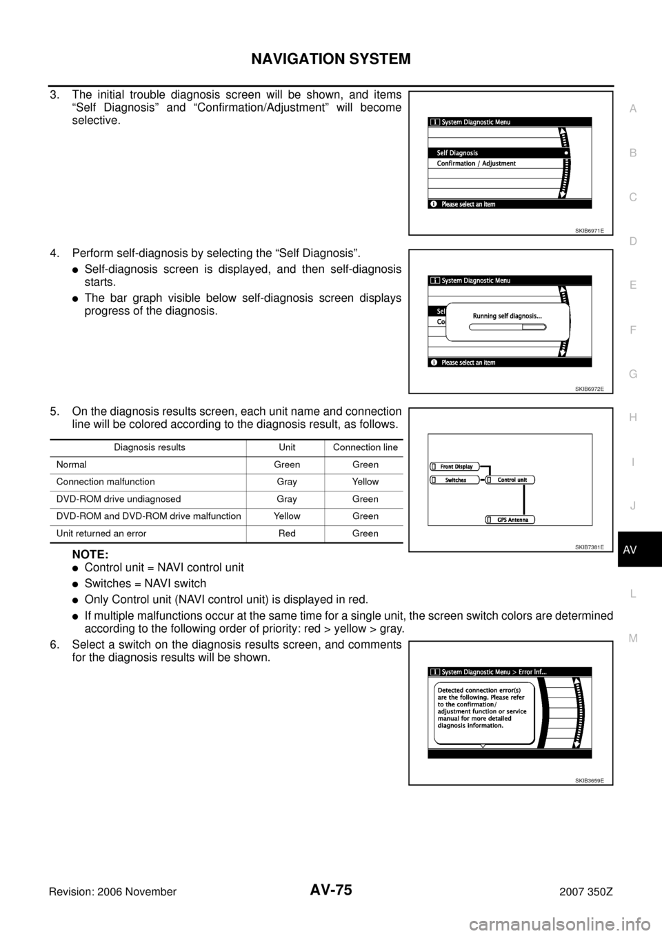
3. The initial trouble diagnosis screen will be shown, and items
“Self Diagnosis” and “Confirmation/Adjustment” will become
selective.
4. Perform self-diagnosis by selecting the “Self Diagnosis”.
�Self-diagnosis screen is displayed, and then self-diagnosis
starts.
�The bar graph visible below self-diagnosis screen displays
progress of the diagnosis.
5. On the diagnosis results screen, each unit name and connection
line will be colored according to the diagnosis result, as follows.
NOTE:
�Control unit = NAVI control unit
�Switches = NAVI switch
�Only Control unit (NAVI control unit) is displayed in red.
�If multiple malfunctions occur at the same time for a single unit, the screen switch colors are determined
according to the following order of priority: red > yellow > gray.
6. Select a switch on the diagnosis results screen, and comments
for the diagnosis results will be shown.
SKIB6971E
SKIB6972E
Diagnosis results Unit Connection line
Normal Green Green
Connection malfunction Gray Yellow
DVD-ROM drive undiagnosed Gray Green
DVD-ROM and DVD-ROM drive malfunction Yellow Green
Unit returned an error Red Green
SKIB7381E
SKIB3659E
Page 76 of 116
AV-76
NAVIGATION SYSTEM
Revision: 2006 November2007 350Z
SELF-DIAGNOSIS RESULT
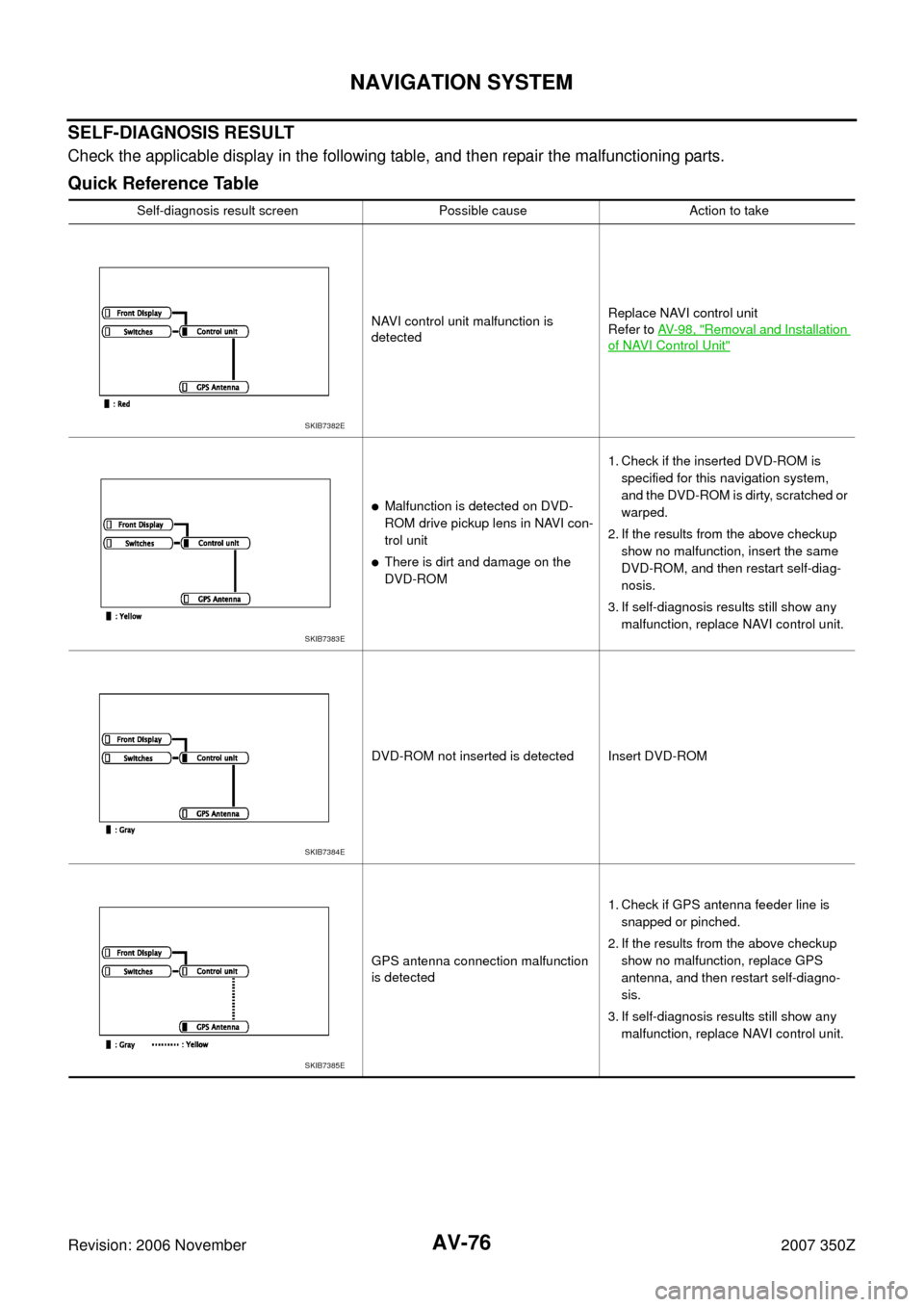
Check the applicable display in the following table, and then repair the malfunctioning parts.
Quick Reference Table
Self-diagnosis result screen Possible cause Action to take
NAVI control unit malfunction is
detectedReplace NAVI control unit
Refer to AV- 9 8 , "
Removal and Installation
of NAVI Control Unit"
�Malfunction is detected on DVD-
ROM drive pickup lens in NAVI con-
trol unit
�There is dirt and damage on the
DVD-ROM1. Check if the inserted DVD-ROM is
specified for this navigation system,
and the DVD-ROM is dirty, scratched or
warped.
2. If the results from the above checkup
show no malfunction, insert the same
DVD-ROM, and then restart self-diag-
nosis.
3. If self-diagnosis results still show any
malfunction, replace NAVI control unit.
DVD-ROM not inserted is detected Insert DVD-ROM
GPS antenna connection malfunction
is detected1. Check if GPS antenna feeder line is
snapped or pinched.
2. If the results from the above checkup
show no malfunction, replace GPS
antenna, and then restart self-diagno-
sis.
3. If self-diagnosis results still show any
malfunction, replace NAVI control unit.
SKIB7382E
SKIB7383E
SKIB7384E
SKIB7385E
Page 78 of 116
AV-78
NAVIGATION SYSTEM
Revision: 2006 November2007 350Z
DISPLAY DIAGNOSIS
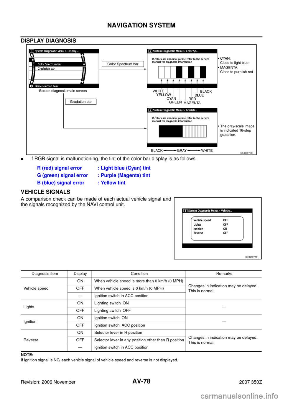
�If RGB signal is malfunctioning, the tint of the color bar display is as follows.
VEHICLE SIGNALS
A comparison check can be made of each actual vehicle signal and
the signals recognized by the NAVI control unit.
NOTE:
If ignition signal is NG, each vehicle signal of vehicle speed and reverse is not displayed.
SKIB6976E
R (red) signal error : Light blue (Cyan) tint
G (green) signal error : Purple (Magenta) tint
B (blue) signal error : Yellow tint
SKIB6977E
Diagnosis item Display Condition Remarks
Vehicle speedON When vehicle speed is more than 0 km/h (0 MPH)
Changes in indication may be delayed.
This is normal. OFF When vehicle speed is 0 km/h (0 MPH)
— Ignition switch in ACC position
LightsON Lighting switch ON
—
OFF Lighting switch OFF
IgnitionON Ignition switch ON
—
OFF Ignition switch ACC position
ReverseON Selector lever in R position
Changes in indication may be delayed.
This is normal. OFF Selector lever in any position other than R position
— Ignition switch in ACC position
Page 80 of 116
AV-80
NAVIGATION SYSTEM
Revision: 2006 November2007 350Z
ERROR HISTORY
Diagnosis results of self-diagnosis depend on if any error occurred during the time after selecting “Self Diag-
nosis” until self-diagnosis results is displayed.
Meanwhile, when an error occurs before selecting “Self Diagnosis”, and if an error does not occur until self-
diagnosis results is displayed, a diagnosis result is judged as normal.
Consequently, a diagnosis needs to be performed with “Error History” for the past error that is not available
with self-diagnosis.
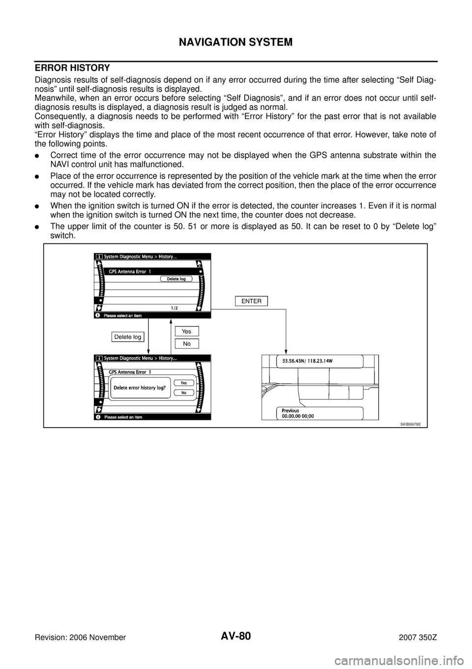
“Error History” displays the time and place of the most recent occurrence of that error. However, take note of
the following points.
�Correct time of the error occurrence may not be displayed when the GPS antenna substrate within the
NAVI control unit has malfunctioned.
�Place of the error occurrence is represented by the position of the vehicle mark at the time when the error
occurred. If the vehicle mark has deviated from the correct position, then the place of the error occurrence
may not be located correctly.
�When the ignition switch is turned ON if the error is detected, the counter increases 1. Even if it is normal
when the ignition switch is turned ON the next time, the counter does not decrease.
�The upper limit of the counter is 50. 51 or more is displayed as 50. It can be reset to 0 by “Delete log”
switch.
SKIB6978E
Page 82 of 116
AV-82
NAVIGATION SYSTEM
Revision: 2006 November2007 350Z
Front Display Connection ErrorDisplay unit power supply and ground
circuit malfunction is detected1. Delete the error history, and turn OFF
ignition switch.
2. Turn ON ignition switch, and make sure
of the error history.
3. If the error item listed left is displayed
again, GO TO 4. If the error item is not
displayed, end the diagnosis. (This is
not a malfunction.)
4. Check display unit power supply and
ground circuit.
5. If the results from the above checkup
show no malfunction, replace display
unit. Error item Possible cause Action to take
Page 83 of 116
NAVIGATION SYSTEM
AV-83
C
D
E
F
G
H
I
J
L
MA
B
AV
Revision: 2006 November2007 350Z
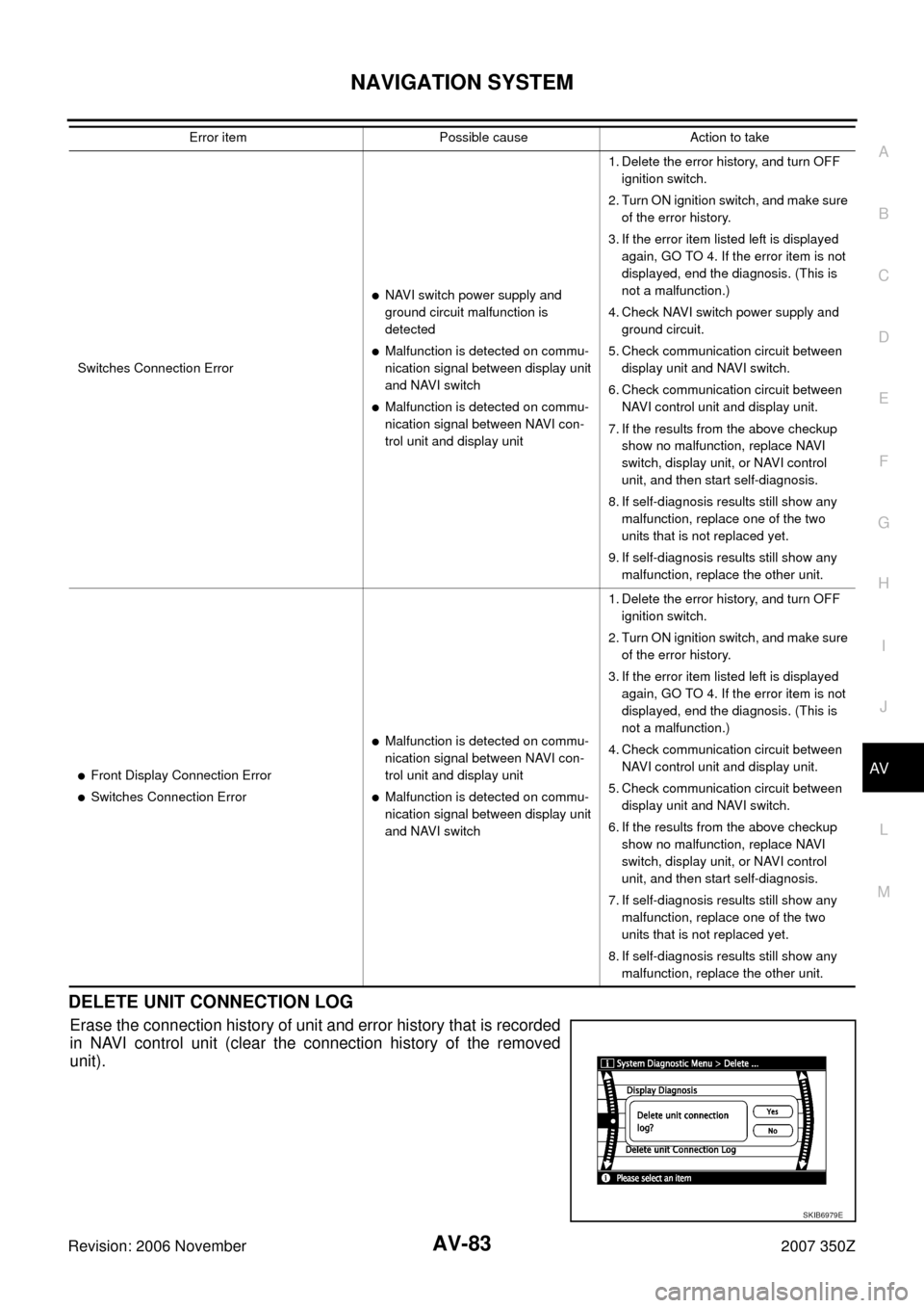
DELETE UNIT CONNECTION LOG
Erase the connection history of unit and error history that is recorded
in NAVI control unit (clear the connection history of the removed
unit).
Switches Connection Error
�NAVI switch power supply and
ground circuit malfunction is
detected
�Malfunction is detected on commu-
nication signal between display unit
and NAVI switch
�Malfunction is detected on commu-
nication signal between NAVI con-
trol unit and display unit1. Delete the error history, and turn OFF
ignition switch.
2. Turn ON ignition switch, and make sure
of the error history.
3. If the error item listed left is displayed
again, GO TO 4. If the error item is not
displayed, end the diagnosis. (This is
not a malfunction.)
4. Check NAVI switch power supply and
ground circuit.
5. Check communication circuit between
display unit and NAVI switch.
6. Check communication circuit between
NAVI control unit and display unit.
7. If the results from the above checkup
show no malfunction, replace NAVI
switch, display unit, or NAVI control
unit, and then start self-diagnosis.
8. If self-diagnosis results still show any
malfunction, replace one of the two
units that is not replaced yet.
9. If self-diagnosis results still show any
malfunction, replace the other unit.
�Front Display Connection Error
�Switches Connection Error
�Malfunction is detected on commu-
nication signal between NAVI con-
trol unit and display unit
�Malfunction is detected on commu-
nication signal between display unit
and NAVI switch1. Delete the error history, and turn OFF
ignition switch.
2. Turn ON ignition switch, and make sure
of the error history.
3. If the error item listed left is displayed
again, GO TO 4. If the error item is not
displayed, end the diagnosis. (This is
not a malfunction.)
4. Check communication circuit between
NAVI control unit and display unit.
5. Check communication circuit between
display unit and NAVI switch.
6. If the results from the above checkup
show no malfunction, replace NAVI
switch, display unit, or NAVI control
unit, and then start self-diagnosis.
7. If self-diagnosis results still show any
malfunction, replace one of the two
units that is not replaced yet.
8. If self-diagnosis results still show any
malfunction, replace the other unit. Error item Possible cause Action to take
SKIB6979E
Page 84 of 116
AV-84
NAVIGATION SYSTEM
Revision: 2006 November2007 350Z
All Images Are Not DisplayedNKS000DI
Symptom: RGB image such as a map screen is not displayed.
1. CHECK CONDITION
Check if brightness of screen changes when button on NAVI switch is turned on after turning on ignition
switch.
Does brightness of screen change?
YES >> GO TO 5.
NO >> GO TO 2.
2. CHECK NAVI CONTROL UNIT POWER SUPPLY AND GROUND CIRCUIT
1. Check voltage between NAVI control unit harness connector ter-
minals and ground.
2. Turn ignition switch OFF.
3. Disconnect NAVI control unit connector.
4. Check continuity between NAVI control unit harness connector
B104 terminal 1 and ground.
OK or NG
OK >> GO TO 3.
NG >> Repair harness or connector.
Terminals
OFF ACC ON (+)
(–)
Connector Terminal
B1042
GroundBattery
voltageBattery
voltageBattery
voltage
50 VBattery
voltageBattery
voltage
1 – Ground : Continuity should exist.
SKIB7018E
SKIB7019E
Page 85 of 116
NAVIGATION SYSTEM
AV-85
C
D
E
F
G
H
I
J
L
MA
B
AV
Revision: 2006 November2007 350Z
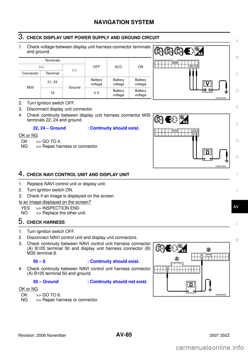
3. CHECK DISPLAY UNIT POWER SUPPLY AND GROUND CIRCUIT
1. Check voltage between display unit harness connector terminals
and ground.
2. Turn ignition switch OFF.
3. Disconnect display unit connector.
4. Check continuity between display unit harness connector M35
terminals 22, 24 and ground.
OK or NG
OK >> GO TO 4.
NG >> Repair harness or connector.
4. CHECK NAVI CONTROL UNIT AND DISPLAY UNIT
1. Replace NAVI control unit or display unit.
2. Turn ignition switch ON.
3. Check if an image is displayed on the screen.
Is an image displayed on the screen?
YES >> INSPECTION END
NO >> Replace the other unit.
5. CHECK HARNESS
1. Turn ignition switch OFF.
2. Disconnect NAVI control unit and display unit connectors.
3. Check continuity between NAVI control unit harness connector
(A) B105 terminal 50 and display unit harness connector (B)
M35 terminal 8.
4. Check continuity between NAVI control unit harness connector
(A) B105 terminal 50 and ground.
OK or NG
OK >> GO TO 6.
NG >> Repair harness or connector.
Terminals
OFF ACC ON (+)
(–)
Connector Terminal
M3521, 23
GroundBattery
voltageBattery
voltageBattery
voltage
19 0 VBattery
voltageBattery
voltage
22, 24 – Ground : Continuity should exist.
SKIB7395E
SKIB7396E
50 – 8 : Continuity should exist.
50 – Ground : Continuity should not exist.
SKIB6983E