Page 853 of 1449

MANUAL TRANSMISSION - On-vehicle Service22A-45
Output voltage:
Above 70 mV when measured with the circuit
tester
Above 200 mVP-P when measured with the
oscilloscope
4. If the output voltage is lower than the above values, the
following reasons may be suspected. Check or replace
the wheel speed sensor.
DExcessive clearance between the ball piece of the
wheel speed sensor and ABS rotor
DWheel speed sensor faul
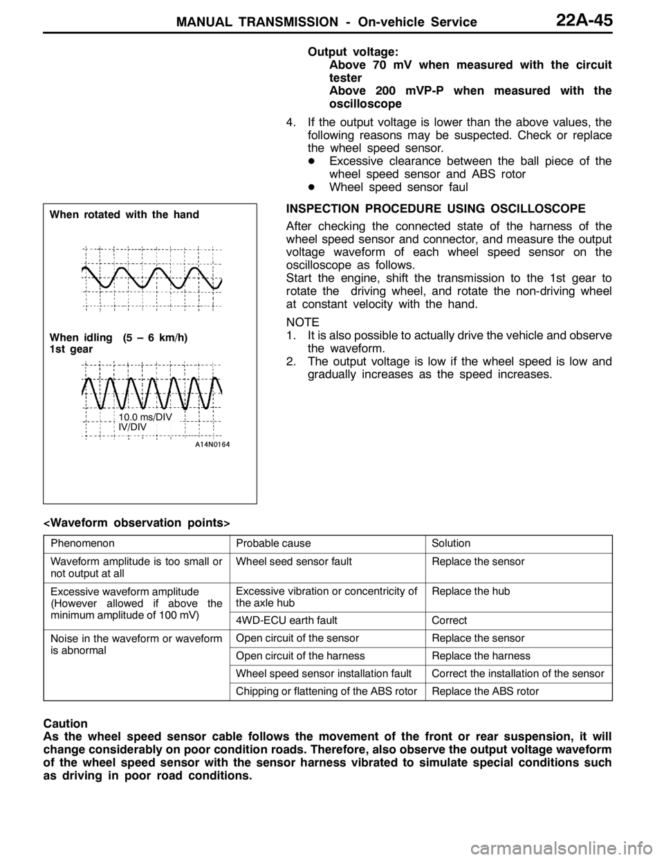
INSPECTION PROCEDURE USING OSCILLOSCOPE
After checking the connected state of the harness of the
wheel speed sensor and connector, and measure the output
voltage waveform of each wheel speed sensor on the
oscilloscope as follows.
Start the engine, shift the transmission to the 1st gear to
rotate the driving wheel, and rotate the non-driving wheel
at constant velocity with the hand.
NOTE
1. It is also possible to actually drive the vehicle and observe
the waveform.
2. The output voltage is low if the wheel speed is low and
gradually increases as the speed increases.
PhenomenonProbable causeSolution
Waveform amplitude is too small or
not output at allWheel seed sensor faultReplace the sensor
Excessive waveform amplitude
(However allowed if above the
iilit df100V)
Excessive vibration or concentricity of
the axle hubReplace the hub
(
minimum amplitude of 100 mV)4WD-ECU earth faultCorrect
Noise in the waveform or waveform
ibl
Open circuit of the sensorReplace the sensor
is abnormalOpen circuit of the harnessReplace the harness
Wheel speed sensor installation faultCorrect the installation of the sensor
Chipping or flattening of the ABS rotorReplace the ABS rotor
Caution
As the wheel speed sensor cable follows the movement of the front or rear suspension, it will
change considerably on poor condition roads. Therefore, also observe the output voltage waveform
of the wheel speed sensor with the sensor harness vibrated to simulate special conditions such
as driving in poor road conditions.
When rotated with the hand
When idling (5 – 6 km/h)
1st gear
10.0 ms/DIV
IV/DIV
Page 954 of 1449

REAR AXLE -Special Tools/Troubleshooting 27B-8
NumberNameO.D.mm
BoxMB990551Box–
CBaseMB990989Base–
ABCBase
MB990990Tool A25A
Tool
MB990991Tool B28
ToolMB990992Tool C31
Installer adapterBrass bar
Bar (one-touch type) AB
C
Toolbox
Tool numberO.D.mmTool numberO.D.mm
AMB99092639AMB99093363.5
MB99092745MB99093467.5
MB99092849.5MB99093571.5
MB99092951MB99093675.5
MB99093054MB99093779
MB99093157BMB990938-
MB99093261CMB990939-
TROUBLESHOOTING
BASIC TROUBLESHOOTING CONDITIONS
Refer to GROUP 00 – How to Use Troubleshooting/Inspection Service Points.
NOTE
Before starting the troubleshooting procedure, make sure that the following items have been checked
okay.
DThe correct steering wheel has been properly installed in the neutral position of the steering column
shaft.
DTire and wheel sizes are correct with correct specifications. Inflation pressure, balance, and wear
conditions are okay.
DWheel alignment is correct.
DThe engine, suspension, and other parts have not been remodeled so as to affect the AYC system.
DIAGNOSIS FUNCTION
READING THE DIAGNOSIS CODES
Read the diagnosis code using MUT-IIor ACD mode indicator
lamp. (Refer to GROUP 00 – How to Use Troubleshooting/
Inspection Service Points.)
NOTE
Connect the MUT-IIto the 16-pin diagnosis connector.
Page 1030 of 1449

FRONT SUSPENSION -Special Tools/On-vehicle Service33A-4
Tools UseName Number
MB990800Ball joint remover &
installerLower arm ball joint dust cover press-in
MB990651BarLower arm pillow ball bushing removal and
press-fitting
MB990816Bushing remover &
installer base
MB991576Base
MB990635,
MB991113 or
MB991406Steering linkage
pullerTie rod end and knuckle disconnection
ON-VEHICLE SERVICE
WHEEL ALIGNMENT CHECK AND
ADJUSTMENT
Measure the wheel alignment with the vehicle parked on a
level surface.
The front suspension, steering system, and wheels should be
serviced to normal condition prior to measurement of wheel
alignment.
TOE-IN
Standard value:
At the centre of tyre tread 0±2mm
Toe angle (per wheel) 0_00’±05’
1. Adjust the toe-in by undoing the clip and lock nut, and
turning the left and right tie rod turnbuckles by the same
amount (in opposite directions).
NOTE
The toe will move out as the left turnbuckle is turned
toward the front of the vehicle and the right turnbuckle
is turned toward the rear of the vehicle.
2. Install the clip and tighten the lock nut to the specified torque.
Clip
Lock nut
Page 1039 of 1449

FRONT SUSPENSION -Stabilizer Bar33A-13
Pre-removal Operation
DSteering Wheel and Air Bag Module Assembly
Removal (Refer to GROUP 37A.)
DClock Spring Removal (Refer to GROUP 52B.)
DCrossmember Bar Removal (Refer to P.33A-15.)
DCentermember Removal (Refer to GROUP 32.)
DFront Exhaust Pipe Removal (Refer to GROUP 15.)Post-installation Operation
DFront Exhaust Pipe Installation (Refer to GROUP
15.)
DCentermember Installation (Refer to GROUP 32.)
DCrossmember Bar Installation (Refer to P.33A-15.)
DClock Spring Installation (Refer to GROUP 52B.)
DSteering Wheel and Air Bag Module Assembly
Installation (Refer to GROUP 37A.)
DCheck the Dust Cover for Cracks or Damage by
Pushing it with Finger.
DChecking Steering Wheel Position with Wheels
Straight Ahead
DFront Wheel Alignment Check and Adjustment
(Refer to P.33A-4.)
3
4
10
21±4N·m
51
1
2
25±5N·m
18±2N·m
108±10 N·m
52±7N·m*
49±10 N·m
167±9N·m
7
8
9
6
39±5N·m
39±5N·m
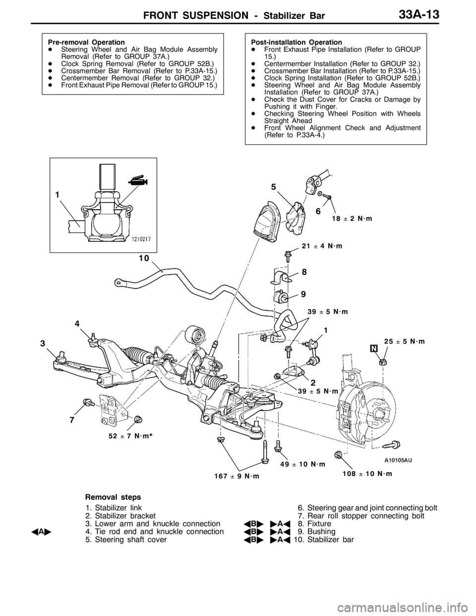
Removal steps
1. Stabilizer link
2. Stabilizer bracket
3. Lower arm and knuckle connection
AA"4. Tie rod end and knuckle connection
5. Steering shaft cover6. Steering gear and joint connecting bolt
7. Rear roll stopper connecting bolt
AB""AA8. Fixture
AB""AA9. Bushing
AB""AA10. Stabilizer bar
Page 1098 of 1449

ABS <4WD> -On-vehicle Service35B-28
SymptomRemedy Probable causes
Noisy or disturbed waveformOpen circuit in sensorReplace sensor
Open circuit in harnessCorrect harness
Incorrectly mounted wheel speed sensorMount correctly
ABS rotor with missing or damaged teethReplace ABS rotor
Caution
Because the wheel speed sensor cables move together with the front and rear suspension, they
vibrate greatly when driving over poor road surfaces. As a result, the sensor harnesses should also
be shaken when monitoring of output waveforms of the wheel speed sensors in order to simulate
conditions such as driving over poor road surfaces.
HYDRAULIC UNIT CHECK
1. Jack up the vehicle and support the vehicle with rigid racks placed at the specified jack-up points
or place the wheels which are checked on the rollers of the braking force tester.
Caution
(1) The roller of the braking force tester and the tyre should be dry during testing.
(2) When testing the front brakes, apply the parking brake, and when testing the rear brakes,
stop the front wheels by chocking them.
2. Turn the ignition key to the “LOCK” (OFF) position and set the MUT-II.
Caution
Turn the ignition key to the “LOCK” (OFF) position before connecting or disconnecting the
MUT-II.
3. After checking that the shift lever is in neutral, start the engine.
4. Use the MUT-IIto force-drive the actuator.
NOTE
(1) During the actuator test, the ABS warning lamp will illuminate and the anti-skid control will be
cancelled.
(2) When the ABS has been interrupted by the fail-safe function, the MUT-IIactuator testing cannot
be carried out.
5. Turn the wheel by hand and check the change in braking force when the brake pedal is depressed.
When using the braking force tester, depress the brake pedal until the braking force is at the following
values, and check that the braking force decreases when the actuator is force-driven.
Front wheel785 - 981 N
Rear wheel588 - 784 N