Page 410 of 473
409 Practical hints
Flat tire
�
Keeping jack in this position, turn
crank3 clockwise until the jack base
meets the ground. Make sure the jack
is vertical (plumb line).
�
Continue to turn the crank until the tire
is a maximum of 1.2 in (3 cm) from the
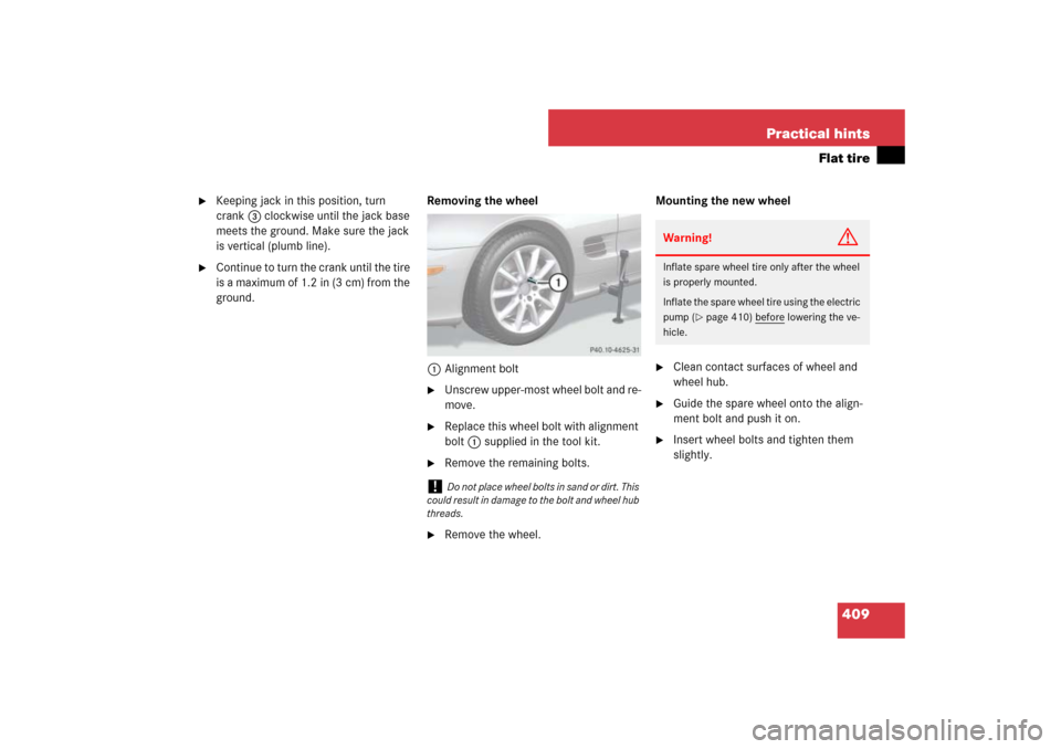
ground.Removing the wheel
1Alignment bolt
�
Unscrew upper-most wheel bolt and re-
move.
�
Replace this wheel bolt with alignment
bolt1 supplied in the tool kit.
�
Remove the remaining bolts.
�
Remove the wheel.Mounting the new wheel
�
Clean contact surfaces of wheel and
wheel hub.
�
Guide the spare wheel onto the align-
ment bolt and push it on.
�
Insert wheel bolts and tighten them
slightly.
!
Do not place wheel bolts in sand or dirt. This
could result in damage to the bolt and wheel hub
threads.
Warning!
G
Inflate spare wheel tire only after the wheel
is properly mounted.
Inflate the spare wheel tire using the electric
pump (
�page 410) before
lowering the ve-
hicle.
Page 411 of 473

�
Take the electric air pump out of the
trunk (
�")
410 Practical hintsFlat tire
�
Unscrew the alignment bolt, install last
wheel bolt and tighten slightly.
Inflating the spare tire (collapsible tire)
�
Take the electric air pump out of the
trunk (
�page 388).1Flap
2Air pump switch
3Electrical plug
4Air hose with pressure gauge and vent
screw
5Union nut
�
Open flap 1 on air pump.
�
Pull out electrical plug 3 and air hose
with the pressure gauge 4.
�
Remove the valve cap from the tire
valve.
�
Screw union nut 5 onto the tire valve.
�
Insert electrical plug 3 into vehicle ci-
gar lighter socket.
Warning!
G
Always replace wheel bolts that are dam-
aged or rusted.
Never apply oil or grease to wheel bolts.
Damaged wheel hub threads should be re-
paired immediately. Do not continue to drive
under these circumstances! Contact an au-
thorized Mercedes-Benz Center or call
Roadside Assistance.
Incorrect wheel bolts or improperly tight-
ened wheel bolts can cause the wheel to
come off. This could cause an accident. Be
sure to use the correct wheel bolts.
Warning!
G
Only use genuine equipment
Mercedes-Benz wheel bolts. They are identi-
fied by the Mercedes star. Other wheel bolts
may come loose.
Do not tighten the wheel bolts when the ve-
hicle is raised. Otherwise the vehicle could
fall off the jack.!
Do not lower the vehicle before inflating the
spare wheel tire. Otherwise the rim may be dam-
aged.
Warning!
G
Observe instructions on air pump label.
Page 413 of 473

412 Practical hintsFlat tireLowering the vehicle�
Lower vehicle by turning crank coun-
terclockwise until the full weight of the
vehicle is resting on the ground.
�
Pull the jack out of the jack support
tube.
1 - 5 Wheel bolts
�
Tighten the five wheel bolts evenly, fol-
lowing the diagonal sequence illustrat-
ed (1 to 5), until all bolts are tight.
Observe a tightening torque of 96 lb-ft
(130 Nm).
�
Before storing the jack in the trunk,
crank back to storage position and fold
in the arm.
Replacing jack support tube cover
�
Slide tongue of cover under the upper
edge of the tube opening.
�
Applying even pressure, press cover
until it snaps into place.
Be careful not to damage the locking
tabs or clamp the plastic retaining
strap.
i
The flat tire may be transported in the trunk
when the retractable hardtop is raised. If avail-
able, use a protective sheet on the spare wheel.
Vehicles with TPMS or Advanced TPMS*:
Do not activate the tire inflation pressure moni-
tor until a full size wheel/tire with functioning
sensor has been placed back into service on the
vehicle.
Warning!
G
Have the tightening torque checked after
changing a wheel. The wheels could come
loose if they are not tightened to a torque of
96 lb-ft (130 Nm).Warning!
G
When turning the wheel wrench to tighten
the wheel bolts, make sure you position
hands on the wrench in such a way that you
avoid injury to yourself, such as scraping
your hands against the wheel. Make sure
turning the wheel wrench will not scratch or
damage the wheel rim.
i
For information on storing the spare wheel
back into the trunk, see “Storing the spare wheel
after use” (
�page 390).
��
Page 424 of 473
1Cover on passenger side of front
bumper
To remove cover:�
Press")
423 Practical hints
Towing the vehicle
Installing towing eye bolt
FrontExample illustration (SL 550 and SL 600
without Sport Package)1Cover on passenger side of front
bumper
To remove cover:�
Press mark on cover 1 in direction of
arrow.
�
Lift cover1off to reveal the threaded
hole for towing eye bolt.To reinstall cover:
�
Fit locking tabs of cover under the
lower edge of the opening in the
bumper.
�
Apply even pressure on the upper part
of the cover until it snaps into place.
Rear
1Cover on passenger side of rear
bumper
To remove cover:
�
Insert flat, blunt object as a lever into
upper left or right recess of cover 1.
�
Loosen cover 1 using the lever.
�
Fold cover 1 down in direction of ar-
row to reveal the threaded hole for the
towing eye bolt.
To reinstall cover:
�
Fit cover 1 and snap into place.
Installing towing eye bolt
�
Take the towing eye bolt and the wheel
wrench from the vehicle tool kit
(�page 388).
�
Screw towing eye bolt into threaded
hole to its stop.
�
Insert wheel wrench into towing eye
and tighten towing eye bolt by turning
it clockwise.
Removing towing eye bolt
�
Take the wheel wrench from the
vehicle tool kit (
�page 388).
�
Insert wheel wrench into towing eye
and loosen towing eye bolt by turning it
counterclockwise.
�
Remove towing eye bolt.
Page 432 of 473
431 Technical data
Identification labels
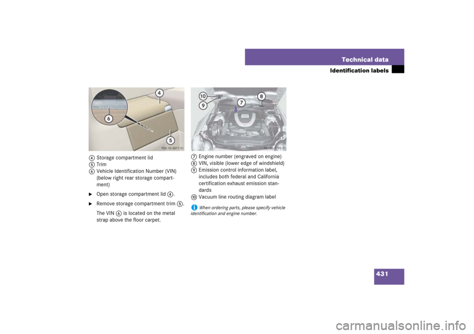
4Storage compartment lid
5Trim
6Vehicle Identification Number (VIN)
(below right rear storage compart-
ment)�
Open storage compartment lid 4.
�
Remove storage compartment trim 5.
The VIN 6 is located on the metal
strap above the floor carpet.7Engine number (engraved on engine)
8VIN, visible (lower edge of windshield)
9Emission control information label,
includes both federal and California
certification exhaust emission stan-
dards
aVacuum line routing diagram label
i
When ordering parts, please specify vehicle
identification and engine number.
Page 451 of 473
450 Technical dataFuels, coolants, lubricants, etc.To provide important corrosion protection,
the solution must be at least 45% anticor-
rosion/antifreeze (equivalent to freeze
protection to approx. - 22°F [-30°C]). If
you use a solution that is more than 55%
anticorrosion/antifreeze (freeze protec-
tion to approx. - 49°F [-45°C]), the engine
temperature will increase due to the lower
heat transfer capability of the solution.
Therefore, do not use more than this
amount of anticorrosion/antifreeze.If the coolant level is low, water and
MB 325.0 Anticorrosion/Antifreeze
should be used to bring it up to the proper
level (have cooling system checked for
signs of leakage). Please make sure the
mixture is in accordance with label instruc-
tions.
The water in the cooling system must meet
minimum requirements, which are usually
satisfied by normal drinking water. If you
are not sure about the water quality, con-
sult an authorized Mercedes-Benz Center.
Page 456 of 473

455 Index
Center console
Lower part 32
Upper part 31
Central locking
Automatic 119, 162
Central locking/unlocking switch 31,
119
Locking/unlocking from inside 119
Certification label 430
Check engine see Lamps, indicator and
warning
Checking tire pressure electronically with
the Advanced Tire Pressure Monitoring
System (Advanced TPMS)*,
(Canada only) 298
Children in the vehicle
Air bags 83
Front passenger front air bag off indica-
tor lamp 76, 345
Infant and child restraint systems 83
Occupant Classification System
(OCS) 72
Cigarette lighter 239
Clock 25, 157
Cockpit 24
Cold tire inflation pressure 312COMAND system 31
Driving instructions 268
Combination switch
High beam 56, 133
Turn signals 56
Windshield wipers 57
Consumer battery 281
Control and operation of radio
transmitters 268
Control system 139, 142
Control system menus
AMG Menu 146
AUDIO 149
NAV 151
Settings 153
Standard display 145
TEL* 165
Trip computer 163
Vehicle status message memory 152
Control system submenus 143
Convenience 162
Instrument cluster 156
Lighting 159
Time 157
Vehicle 162
Convenience feature 201Coolant 449
Anticorrosion/antifreeze mixing ratio
and quantity 451
Checking coolant level 280
Coolant warning lamp 337
Messages in the multifunction
display 371, 373
Temperature 270
Temperature gauge 137
Corner-illuminating front fog lamps 132
Corner-illuminating front fog lamps*
Replacing bulbs 397
Courtesy lighting 135
Cruise control 209
Messages in the multifunction
display 352, 353
Cup holder 238
Curb weight 312
D
Daytime running lamp mode 130
Setting 159
Deep water see Standing water
Defogging, Windshield 191
Defrosting, Front 190
Defrosting, Rear 183
Page 458 of 473

457 Index
Driving systems 209
ABC 225
Cruise control 209
Distronic* 213
Parktronic* 228
DTR see Distronic*
E
Easy-entry/exit feature 46, 162
Messages in the multifunction
display 375
Electric air pump 389, 410
Electrical outlet see Power outlet
Electro-hydraulic brake system 87, 92
Activation 93
Deactivation 94
Driving hints 95
Messages in the multifunction
display 367, 368
Self-check 94
Warning lamp 92
Electronic Stability Program see ESP
®
Emergency calls
Tele Aid 244, 245
Emergency engine shut-down 426
Emergency operation (Limp-Home
Mode) 179Emergency operations
Automatic transmission (Limp-Home
Mode) 179
Glove box, Unlocking 392
Load assist, Lowering 394
Locking/unlocking the vehicle 391,
393
Remote door unlock, Tele Aid 250
Trunk lid, Releasing from the
inside 117
Trunk lid, Unlocking 392
Emergency Tensioning Device see ETD
Emission control 269
Information label 431
System warranties 10
Vacuum line routing diagram
label 431
Engine
Block heater (Canada only) 317
Break-in recommendations 258
Cleaning 324
Compartment 274
Malfunction indicator lamp 29, 336
Number 431
Poly-V-belt layout 432
Starting 52Tachometer 29
Technical data 433
Turning off 62
Engine coolant see Coolant
Engine oil 275, 446
Adding 278, 444
Additives 446
Checking level, With control
system 276
Checking level, With oil dipstick 278
Consumption 275
Filler neck 278, 279
Messages in the multifunction
display 277, 375
Oil dipstick 278
ESP
®
87, 89
Switch 32
Switching off 91
Switching on 92
Synchronizing 355
Warning lamp 27, 332
ETD 81
Safety guidelines 70
Warning and indictor lamps 342
Exterior lamp switch 128
Exterior rear view mirrors 48, 180