Page 499 of 570
498 Practical hints
Flat tire
Mounting the spare wheel
Preparing the vehicle
�Prepare the vehicle as described
(
�page 497).
�Take the wheel wrench and the vehicle
jack from the vehicle tool kit
(
�page 473).
�Take the spare wheel from the wheel
well under the cargo compartment
floor (
�page 476).Lifting the vehicle
�Prevent the vehicle from rolling away
by blocking wheels with wheel chocks
or other sizable objects.
One wheel chock is included with the
vehicle tool kit (
�page 473).
When changing wheel on a level surface:
�Place the wheel chock in front of and
another sizable object behind the
wheel that is diagonally opposite to the
wheel being changed.
Always try lifting the vehicle using the jack
on a level surface. However, should cir-
cumstances require you to do so on a hill,
place the wheel chock and another sizable
object as follows:
�Place the wheel chock and another
sizable object on the downhill side
blocking both wheels of the axle not
being worked on.
Warning!G
The jack is designed exclusively for jacking
up the vehicle at the jack take-up brackets
built into both sides of the vehicle. To help
avoid personal injury, use the jack only to lift
the vehicle during a wheel change. Never
get beneath the vehicle while it is supported
by the jack. Keep hands and feet away from
the area under the lifted vehicle. Always
firmly set parking brake and block wheels
before raising vehicle with jack.
Do not disengage parking brake while the
vehicle is raised. Be certain that the jack is
always vertical (plumb line) when in use,
especially on hills. Always try to use the jack
on level surface.
Make sure the jack arm is fully seated in the
jack take-up bracket. Always lower the vehi-
cle onto sufficient capacity jackstands be-
fore working under the vehicle.
Page 501 of 570

500 Practical hints
Flat tire
Removing the wheel
1Alignment bolt
�Unscrew upper-most wheel bolt and
remove.
�Replace this wheel bolt with alignment
bolt1 supplied in the vehicle tool kit
(
�page 472).
�Remove the remaining wheel bolts.
�Remove the wheel.Mounting the spare wheel
1Wheel bolt for 18", 19", 20" and 21"
light alloy wheels and R 63 AMG spare
wheel
2Wheel bolt for 17" light alloy wheels or
18" spare wheel (located in trunk with
spare wheel)�Clean contact surfaces of wheel and
wheel hub.
!Do not place wheel bolts in sand or dirt. This
could result in damage to the bolts and wheel
hub threads.
!Wheel bolts2 must be used when mount-
ing 17" wheels or the 18" spare wheel with
collapsible tire. The use of any wheel bolts other
than wheel bolts2 for 17" wheels or the
18" spare wheel with collapsible tire will physi-
cally damage the vehicle’s brakes.
!To avoid paint damage, place wheel flat
against hub and hold it there while installing first
wheel bolt.
Warning!G
Always replace wheel bolts that are
damaged or rusted.
Never apply oil or grease to wheel bolts.
Damaged wheel hub threads should be
repaired immediately. Do not continue to
drive under these circumstances! Contact
an authorized Mercedes-Benz Light Truck
Center or call Roadside Assistance.
Incorrect wheel bolts or improperly tight-
ened wheel bolts can cause the wheel to
come off. This could cause an accident.
Make sure to use the correct wheel bolts.
Page 502 of 570
501 Practical hints
Flat tire
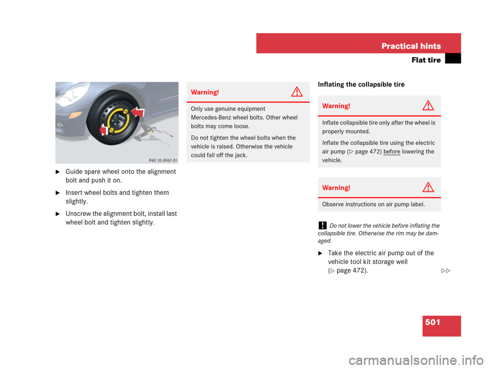
�Guide spare wheel onto the alignment
bolt and push it on.
�Insert wheel bolts and tighten them
slightly.
�Unscrew the alignment bolt, install last
wheel bolt and tighten slightly.Inflating the collapsible tire
�Take the electric air pump out of the
vehicle tool kit storage well
(
�page 472).
Warning!G
Only use genuine equipment
Mercedes-Benz wheel bolts. Other wheel
bolts may come loose.
Do not tighten the wheel bolts when the
vehicle is raised. Otherwise the vehicle
could fall off the jack.Warning!G
Inflate collapsible tire only after the wheel is
properly mounted.
Inflate the collapsible tire using the electric
air pump (
�page 472) before lowering the
vehicle.
Warning!G
Observe instructions on air pump label.
!Do not lower the vehicle before inflating the
collapsible tire. Otherwise the rim may be dam-
aged.
��
Page 503 of 570

502 Practical hints
Flat tire
Electric air pump
1Flap
2On/off switch
3Electrical plug
4Air hose with pressure gauge and vent
screw
5Union nut
�Open flap 1 on electric air pump.
�Pull out electrical plug 3 and air hose
with pressure gauge 4.
�Remove the valve cap from the
collapsible tire valve.
�Screw union nut 5 onto the
collapsible tire valve.
�Insert electrical plug 3 into a power
outlet (
�page 322).
�Turn the SmartKey in the starter switch
to position1.
�Vehicles with KEYLESS-GO*:
Press the KEYLESS-GO start/stop
button once without depressing the
brake pedal.
�Press I on electric air pump switch 2.
The electric air pump should now
switch on and inflate the collapsible
tire.
�Inflate the spare wheel tire to the
recommended tire inflation pressure
given in the “Technical data” section
(
�page 532).
This takes about 5 minutes for the
collapsible tire.
!The cigarette lighter* (�page 319) is not
designed for use with the electric air pump. Use
a power outlet (
�page 322) for electric air
pump operation.
Warning!G
Air hose 4 and union nut5 can become
hot during inflation. Exercise proper caution
to avoid burning yourself when using the
equipment.
!Do not operate the electric air pump longer
than 8 minutes without interruption. Otherwise it
may overheat.
You may operate the electric air pump again
after it has cooled off.
��
Page 504 of 570
503 Practical hints
Flat tire
�Press 0 on electric air pump switch 2.
�Turn the SmartKey in the starter switch
to position0.
�Vehicles with KEYLESS-GO*:
Press the KEYLESS-GO start/stop
button twice without depressing
the brake pedal.
�If the tire inflation pressure is above
the recommended tire inflation pres-
sure given in this Operator’s Manual,
release excess tire inflation pressure
using the vent screw.
�Detach the electric air pump.
�Store the electrical plug and the air
hose behind the flap and place the
electric air pump back in the vehicle
tool kit storage well.Lowering the vehicle
�Lower vehicle by turning crank coun-
terclockwise until vehicle is resting ful-
ly on its own weight.
�Remove the jack.
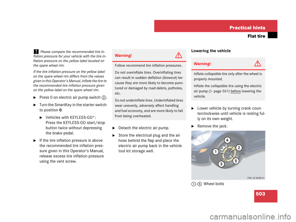
1-5Wheel bolts
!Please compare the recommended tire in-
flation pressure for your vehicle with the tire in-
flation pressure on the yellow label located on
the spare wheel rim.
If the tire inflation pressure on the yellow label
on the spare wheel rim differs from the values
given in this Operator’s Manual, inflate the tire to
the recommended tire inflation pressure given
on the yellow label on the spare wheel rim.Warning!G
Follow recommend tire inflation pressures.
Do not overinflate tires. Overinflating tires
can result in sudden deflation (blowout) be-
cause they are more likely to become punc-
tured or damaged by road debris, potholes,
etc.
Do not underinflate tires. Underinflated tires
wear unevenly, adversely affect handling
and fuel economy, and are more likely to fail
from being overheated.Warning!G
Inflate collapsible tire only after the wheel is
properly mounted.
Inflate the collapsible tire using the electric
air pump (
�page 501) before lowering the
vehicle.
Page 505 of 570
504 Practical hints
Flat tire
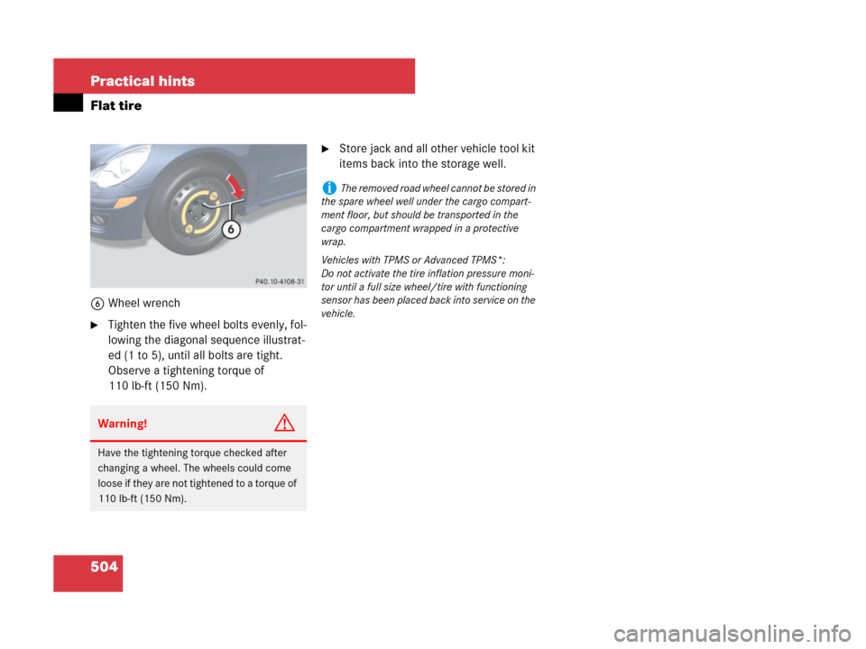
6Wheel wrench
�Tighten the five wheel bolts evenly, fol-
lowing the diagonal sequence illustrat-
ed (1 to 5), until all bolts are tight.
Observe a tightening torque of
110 lb-ft (150 Nm).
�Store jack and all other vehicle tool kit
items back into the storage well.
Warning!G
Have the tightening torque checked after
changing a wheel. The wheels could come
loose if they are not tightened to a torque of
110 lb-ft (150 Nm).
iThe removed road wheel cannot be stored in
the spare wheel well under the cargo compart-
ment floor, but should be transported in the
cargo compartment wrapped in a protective
wrap.
Vehicles with TPMS or Advanced TPMS*:
Do not activate the tire inflation pressure moni-
tor until a full size wheel/tire with functioning
sensor has been placed back into service on the
vehicle.
Page 522 of 570
521 Practical hints
Fuses
Fuse box in engine compartment
The main fuse box is located on the pas-
senger side of the engine compartment.
�Open the hood (�page 364).
1Clamp
2Main fuse box cover
�Release clamp1.
�Lift fuse box cover2 up.
�Install fuse box cover in reverse order.
�Close the hood after checking or re-
placing fuses (
�page 366).
Fuse box in cargo compartment
The fuse box is located under the cargo
compartment cover on the right-hand side
of the spare wheel well.
�Open the tailgate (�page 123).
�Lift the cargo compartment cover
(
�page 472).
�Secure cargo compartment cover with
strap (
�page 473).
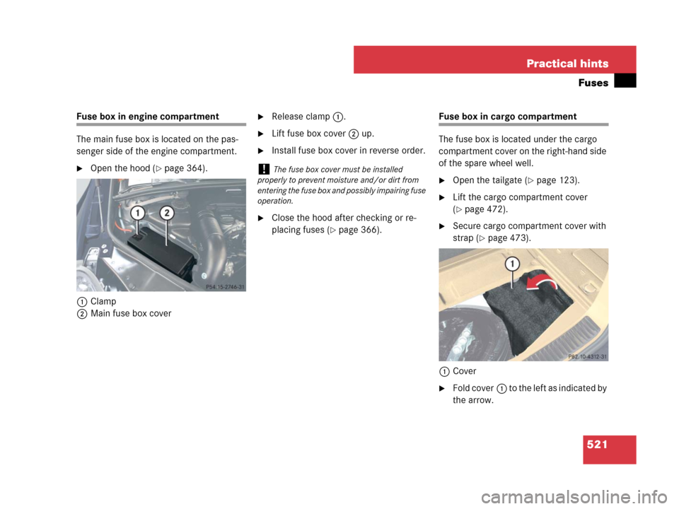
1Cover
�Fold cover1 to the left as indicated by
the arrow.
!The fuse box cover must be installed
properly to prevent moisture and/or dirt from
entering the fuse box and possibly impairing fuse
operation.
Page 535 of 570
534 Technical data
Rims and tires
Spare wheel (collapsible tire)
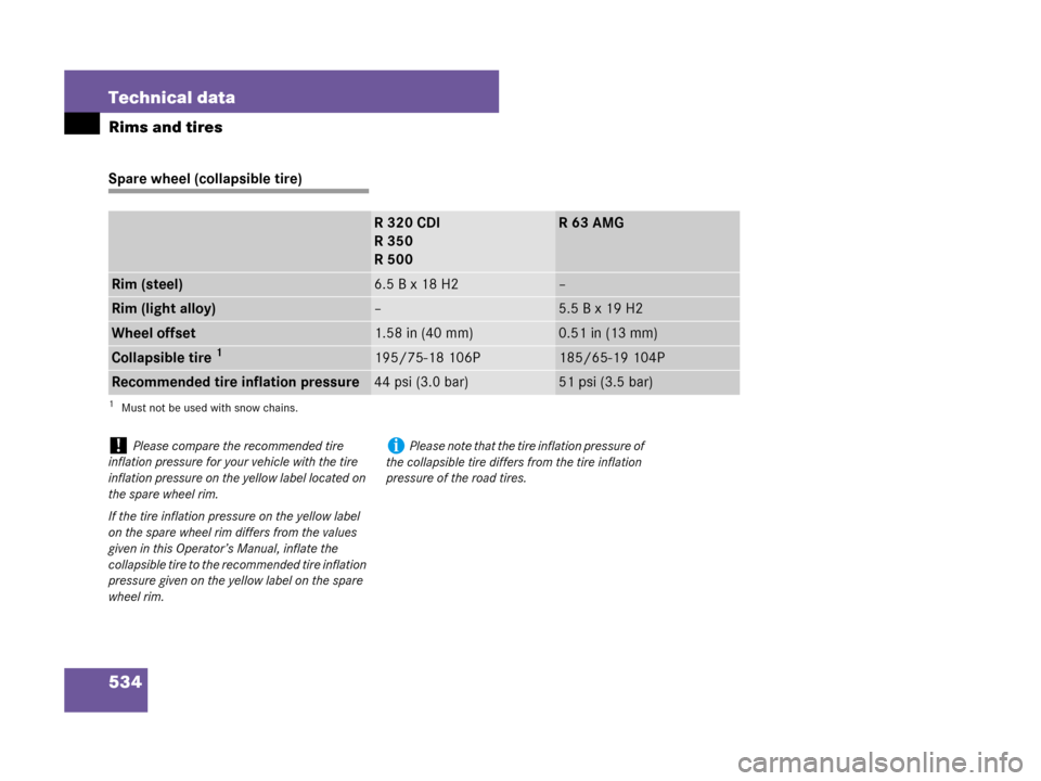
R320CDI
R350
R500R63AMG
Rim (steel)6.5 B x 18 H2–
Rim (light alloy)–5.5 B x 19 H2
Wheel offset1.58 in (40 mm)0.51 in (13 mm)
Collapsible tire 1
1Must not be used with snow chains.
195/75-18 106P185/65-19 104P
Recommended tire inflation pressure44 psi (3.0 bar)51 psi (3.5 bar)
!Please compare the recommended tire
inflation pressure for your vehicle with the tire
inflation pressure on the yellow label located on
the spare wheel rim.
If the tire inflation pressure on the yellow label
on the spare wheel rim differs from the values
given in this Operator’s Manual, inflate the
collapsible tire to the recommended tire inflation
pressure given on the yellow label on the spare
wheel rim.iPlease note that the tire inflation pressure of
the collapsible tire differs from the tire inflation
pressure of the road tires.