Page 430 of 570
,
should be checked monthly when cold and
inflated to the inflation pressure recom-
mended by the vehicle")
429 Practical hints
What to do if …
Warning!G
Each tire, including the spare (if provided),
should be checked monthly when cold and
inflated to the inflation pressure recom-
mended by the vehicle manufacturer on the
vehicle placard or the tire inflation pressure
label. (If your vehicle has tires of a different
size than the size indicated on the vehicle
placard or the tire inflation pressure label,
you should determine the proper tire infla-
tion pressure for those tires).
As an added safety feature, your vehicle has
been equipped with a tire pressure monitor-
ing system (TPMS) that illuminates a low tire
pressure telltale when one or more of your
tires is significantly underinflated. Accord-
ingly, when the low tire pressure telltale illu-
minates, you should stop and check your
tires as soon as possible, and inflate them to
the proper pressure. Driving on a significant-
ly underinflated tire causes the tire to over-
heat and can lead to tire failure.
Underinflation also reduces fuel efficiency
and tire tread life, and may affect the vehi-
cle’s handling and stopping ability. Please
note that the TPMS is not a substitute for
proper tire maintenance, and it is the driv-
er’s responsibility to maintain correct tire
pressure, even if underinflation has not
reached the level to trigger illumination of
the TPMS low tire pressure telltale.
USA only:
Your vehicle has also been equipped with a
TPMS malfunction indicator to indicate
when the system is not operating properly.
The TPMS malfunction indicator is com-
bined with the low tire pressure telltale.
When the system detects a malfunction, the
telltale will flash for approximately 1 minute
and then remain continuously illuminated.
This sequence will continue upon subse-
quent vehicle start-ups as long as the mal-
function exists. When the malfunction
indicator is illuminated, the system may not
be able to detect or signal low tire pressure
as intended.TPMS malfunctions may occur for a variety
of reasons, including the installation of in-
compatible replacement or alternate tires or
wheels on the vehicle that prevent the TPMS
from functioning properly. Always check the
TPMS malfunction telltale after replacing
one or more tires or wheels on your vehicle
to ensure that the replacement or alternate
tires and wheels allow the TPMS to continue
to function properly.
Page 451 of 570

450 Practical hints
What to do if …
Display messagePossible cause/consequencePossible solution
Tire pressure monitor
inoperativeThe TPMS or Advanced TPMS* is
malfunctioning.�Have the TPMS or Advanced TPMS* checked by an
authorized Mercedes-Benz Light Truck Center.
Tire pressure monitor
inoperative
No wheel sensorsThere are wheels without appropriate wheel
sensors mounted (e.g. winter tires).�Have the TPMS or Advanced TPMS* checked by an
authorized Mercedes-Benz Light Truck Center.
�Have the wheel sensors installed by an authorized
Mercedes-Benz Light Truck Center.
Tire pressure monitor
Wheel sensor missingOne or more sensors are defect (e.g.
battery is empty).
One or more wheels without appropriate
wheel sensors mounted (e.g. spare tire).�Have the TPMS or Advanced TPMS* checked by an
authorized Mercedes-Benz Light Truck Center.
�Have the wheel sensors installed by an authorized
Mercedes-Benz Light Truck Center.
Vehicles with Advanced TPMS*:
The tire pressure for the respective tire is shown in
the multifunction display.
Tire pressure monitor
currently unavailableThe TPMS or Advanced TPMS* is unable to
monitor the tire pressure due to
�a nearby radio interference source.
�excessive wheel sensor temperatures.
�As soon as the causes of the malfunction have been
removed, the TPMS or Advanced TPMS* automati-
cally becomes active again after a few minutes
driving.
Page 473 of 570
472 Practical hints
Where will I find ...?
First aid kit
The first aid kit is stored under the cargo
compartment floor, see “Vehicle tool kit”
(
�page 472).
Vehicle tool kit
The vehicle tool kit is stored under the car-
go compartment floor.
The vehicle tool kit includes:
�Towing eye bolt
�Wheel wrench
�Alignment bolt
�Vehicle jack
�Fuse chart
�Spare fuses
�Fuse extractor
�Collapsible wheel chock
�Wheel bolts for spare wheel
(if applicable, see “Mounting the spare
wheel” (
�page 500))1Cargo compartment floor, lowered
2Handle cover
�Open the tailgate (�page 123).
�Push in handle cover2 and pull
handle in direction of arrow.
�Lift cargo compartment floor 1.
iCheck expiration dates and contents for
completeness at least once a year and replace
missing / expired items.
Page 474 of 570
473 Practical hints
Where will I find ...?
3Securing hook
�Release securing hook 3 (located be-
low the floor handle) from holder.3Securing hook
4Cargo compartment floor, raised
5Upper cargo compartment lip
�Engage securing hook 3 on upper
cargo compartment lip 5.
You can now access the vehicle tool kit.
To remove the vehicle tool kit storage
well casing, proceed as described
on (
�page 476).6Wheel bolt wrench
7Electric air pump
8Jack
9Spare fuses, fuse extractor, fuse chart
aSpare wheel (collapsible tire)
bAlignment bolt
cTowing eye bolt
dCollapsible wheel chock
eSpare wheel bolts
fVehicle tool kit storage well casing
�To remove jack8, loosen the hook
and loop fastener.
!With the cargo compartment cover blind*
installed behind the third-row seats
(
�page 306), disengage cargo compartment
cover blind* and flip it forward. Otherwise the
strap of the securing hook could damage the
cargo compartment cover blind*.
Page 476 of 570

475 Practical hints
Where will I find ...?
Setting up the collapsible wheel chock
The collapsible wheel chock serves to ad-
ditionally secure the vehicle, e.g. while
changing the wheel.
1Tilt the plate upward
2Fold the lower plate outward
3Insert the plate�Tilt both plates upward1.
�Fold the lower plate outward2.
�Guide the tabs of the lower plate all the
way into the openings of base plate3.
For information on where to place wheel
chocks when changing a wheel, see “Lift-
ing the vehicle” (
�page 498).
Spare wheel
Warning!G
The dimensions of the spare wheel are
different from those of the road wheels. As
a result, the vehicle handling characteristics
change when driving with a spare wheel
mounted. Adapt your driving style accord-
ingly.
The spare wheel is for temporary use only.
When driving with a spare wheel mounted,
ensure proper tire inflation pressure and do
not exceed a vehicle speed of
50 mph (80 km/ h).
Drive to the nearest Mercedes-Benz Light
Truck Center as soon as possible to have the
spare wheel replaced with a regular road
wheel.
Never operate the vehicle with more than
one spare wheel mounted.
Do not switch off the ESP
® with a spare
wheel mounted.
Page 477 of 570
.
Removin")
476 Practical hints
Where will I find ...?
Your vehicle is equipped with a spare
wheel with collapsible tire. The spare
wheel is located underneath the cargo
compartment floor (
�page 472).
Removing the spare wheel
1Retaining screw
2Spare wheel
3Vehicle tool kit storage well casing
�Remove the jack from the vehicle tool
kit (
�page 473).
�Loosen retaining screw 1 by turning it
counterclockwise.
�Turn vehicle tool kit storing well
casing3 by approximately 180°.
The electric air pump (
�page 473)
points towards the rear.
�Remove vehicle tool kit storage well
casing 3.
�Remove spare wheel 2.Reinstalling the spare wheel after use
There are two guide pins in the spare wheel
well that serve to hold the spare wheel in
place.
1Guide pins
iFor information on how to mount the spare
wheel, see “Mounting the spare wheel”
(
�page 498).
iIf retaining screw 1 does not come loose,
turn vehicle tool kit storing well casing 3 slightly
counterclockwise. Retaining screw 1 should
then come loose easily.
Page 478 of 570
477 Practical hints
Where will I find ...?
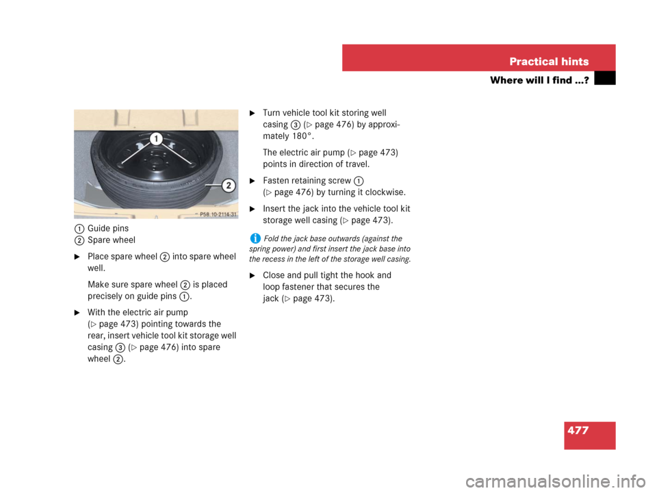
1Guide pins
2Spare wheel
�Place spare wheel 2 into spare wheel
well.
Make sure spare wheel 2 is placed
precisely on guide pins 1.
�With the electric air pump
(
�page 473) pointing towards the
rear, insert vehicle tool kit storage well
casing 3 (
�page 476) into spare
wheel 2.
�Turn vehicle tool kit storing well
casing3 (
�page 476) by approxi-
mately 180°.
The electric air pump (
�page 473)
points in direction of travel.
�Fasten retaining screw 1
(
�page 476) by turning it clockwise.
�Insert the jack into the vehicle tool kit
storage well casing (
�page 473).
�Close and pull tight the hook and
loop fastener that secures the
jack (
�page 473).
iFold the jack base outwards (against the
spring power) and first insert the jack base into
the recess in the left of the storage well casing.
Page 498 of 570

497 Practical hints
Flat tire
�Flat tire
Preparing the vehicle
�Park the vehicle in a safe distance from
moving traffic on a hard, flat surface
when possible.
�Turn on the hazard warning flasher
(
�page 152).
�Turn the steering wheel so that the
front wheels are in a straight-ahead
position.
�Set the parking brake (�page 66).
�Set the automatic transmission to
position P (
�page 197).
�Turn off the engine (�page 67).
�Have any passenger exit the vehicle at
a safe distance from the roadway.
�Remove the SmartKey from the starter
switch.Vehicles with KEYLESS-GO*:
�Turn off the engine by pressing the
KEYLESS-GO* button once
(
�page 67).
�Open the driver’s door (this puts
the starter switch in position 0,
same as with the SmartKey re-
moved from the starter switch). The
driver’s door then can be closed
again.
�Remove the KEYLESS-GO*
start/stop button from the starter
switch.
Warning!G
The dimensions of the spare wheel are
different from those of the road wheels. As
a result, the vehicle handling characteristics
change when driving with a spare wheel
mounted. Adapt your driving style accord-
ingly.
The spare wheel is for temporary use only.
When driving with spare wheel mounted,
ensure proper tire inflation pressure and do
not exceed a vehicle speed of
50 mph (80 km/ h).
Drive to the nearest Mercedes-Benz Light
Truck Center as soon as possible to have the
spare wheel replaced with a regular road
wheel.
Never operate the vehicle with more than
one spare wheel mounted.
Do not switch off the ESP
® with a spare
wheel mounted.
iOpen doors only when conditions are safe to
do so.
iYou can use the power outlets in the cargo
compartment or in the second seat row to
operate the electric air pump even when the
ignition is switched off, e.g. in order to inflate the
collapsible tire (
�page 501).
An emergency shut-off feature ensures that the
vehicle’s electrical voltage does not fall below a
minimum level. If the voltage drops to this mini-
mum level, the power outlets are automatically
switched off. This ensures that enough power
remains to start the engine.