Page 490 of 570

489 Practical hints
Replacing bulbs
Low beam and high beam flasher spot
bulbs
Front turn signal lamp bulbs
�Pull bulb socket 1 out of the head-
lamp housing.
�Pull the turn signal bulb out of bulb
socket 1.
�Insert the new turn signal bulb into bulb
socket 1.
�Insert bulb socket 1 into the head-
lamp housing.Parking and standing lamp bulbs
1Bulb socket for parking and standing
lamp
�Turn bulb socket 1 counterclockwise.
�Pull bulb socket 1 out of the housing.
�Pull the bulb out of bulb socket 1.
�Insert the new parking and standing
lamp bulb into bulb socket 1.
�Insert bulb socket 1 into the housing.
�Turn bulb socket 1 clockwise until it
engages.Corner-illuminating front fog lamp*
bulbs
Example illustration (except R 63 AMG)
1Corner-illuminating front fog lamp*
2Cover
3Retaining screw
Warning!G
Do not remove the low beam/high beam
cover for the Bi-Xenon* headlamp. Because
of high voltage in Bi-Xenon* lamps, it is dan-
gerous to replace the bulb or repair the lamp
and its components. We recommend that
you have such work done by a qualified
technician.
Page 492 of 570

491 Practical hints
Replacing bulbs
�Turn bulb socket 5 counterclockwise.
�Pull bulb socket 5 out of the housing.
�Pull the bulb out of bulb socket 5.
�Insert the new corner-illuminating front
fog lamp bulb into bulb socket 5.
�Insert bulb socket 5 into the housing.
�Turn bulb socket 5 clockwise until it
engages.
�Insert corner-illuminating front fog
lamp 1 back into bumper.
�Fasten retaining screws4.
�Reinsert cover 2 and press it in until it
engages.
�Fasten retaining screw(s)3.Additional turn signal lamps bulbs
The additional turn signal lamps in the
exterior rear view mirrors have LEDs.
If a malfunction occurs or LEDs fail to
function, the entire turn signal unit must
be replaced. Have the turn signal unit re-
placed by an authorized Mercedes-Benz
Light Truck Center.
Front side marker lamp bulbs
Since replacing the side marker lamp bulbs
is a technically highly demanding process,
we recommend you have the side marker
lamp bulbs replaced by an authorized
Mercedes-Benz Light Truck Center.
Replacing bulbs for rear lamps
Before you start to replace a bulb for a rear
lamp, do the following first:
�Turn the combination switch to
positionM (
�page 146).
Tail lamp unit
�Open the tailgate (�page 123).
iTo access the tail lamp units, you have to
remove the cover in the corresponding side trim
panel of the cargo compartment.
Page 493 of 570
492 Practical hints
Replacing bulbs
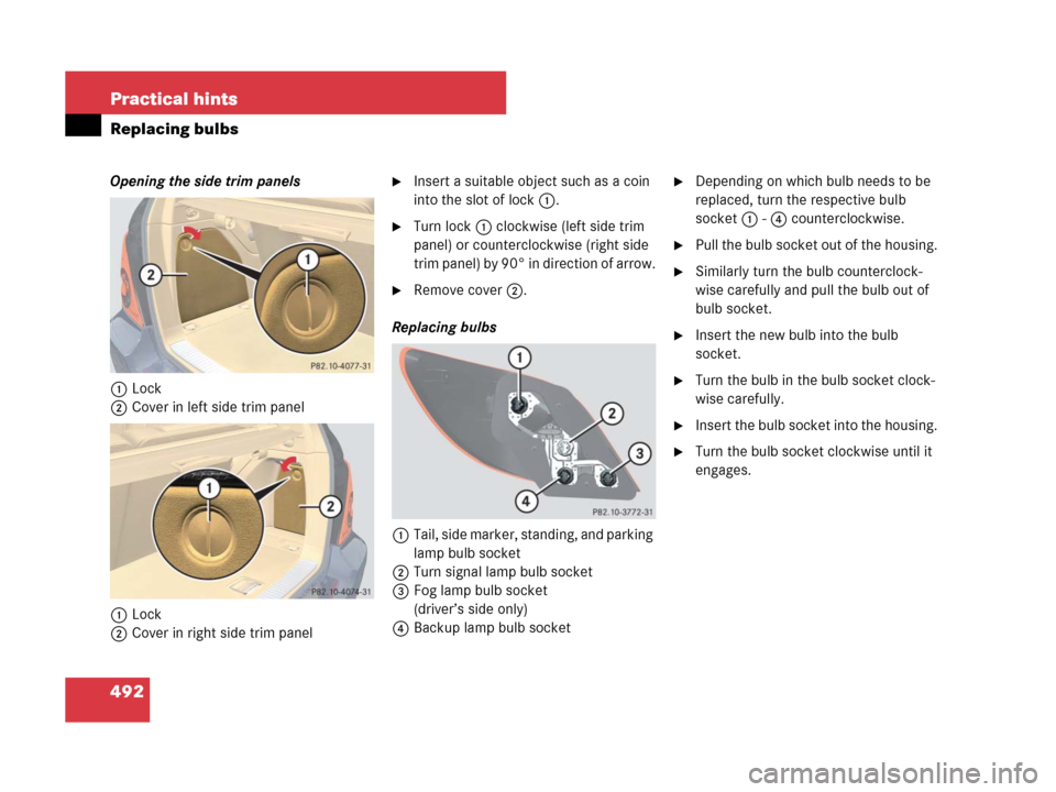
Opening the side trim panels
1Lock
2Cover in left side trim panel
1Lock
2Cover in right side trim panel�Insert a suitable object such as a coin
into the slot of lock1.
�Turn lock1 clockwise (left side trim
panel) or counterclockwise (right side
trim panel) by 90° in direction of arrow.
�Remove cover2.
Replacing bulbs
1Tail, side marker, standing, and parking
lamp bulb socket
2Turn signal lamp bulb socket
3Fog lamp bulb socket
(driver’s side only)
4Backup lamp bulb socket
�Depending on which bulb needs to be
replaced, turn the respective bulb
socket 1 - 4 counterclockwise.
�Pull the bulb socket out of the housing.
�Similarly turn the bulb counterclock-
wise carefully and pull the bulb out of
bulb socket.
�Insert the new bulb into the bulb
socket.
�Turn the bulb in the bulb socket clock-
wise carefully.
�Insert the bulb socket into the housing.
�Turn the bulb socket clockwise until it
engages.
Page 500 of 570
.
The jack take-up brackets")
499 Practical hints
Flat tire
1Wheel wrench
�On whee l to b e c hang ed, l oose n but d o
not yet remove the wheel bolts
(approximately one full turn with wheel
wrench 1).
The jack take-up brackets are located
directly behind the front wheel housings
and in front of the rear wheel housings.
2Take-up bracket
3Jack
4Crank
�Place jack 3 on firm ground.
�Position jack3 under the take-up
bracket2 so that it is always vertical
(plumb-line) as seen from the side,
even if the vehicle is parked on an
incline.
�Turn crank4 clockwise until jack 3
is fully seated in take-up bracket2
and the jack base evenly meets the
ground.
�Continue to turn crank 4 until the
wheel is a maximum of 1.2 in (3 cm)
from the ground.
!Do not position the jack on the body of the
vehicle, as this may cause damage to the
vehicle.
Warning!G
The jack is intended only for lifting the
vehicle briefly for wheel changes. It is not
suited for performing maintenance work
under the vehicle.
�Never start the engine when the vehicle
is raised.
�Never lie down under the raised vehicle.
Page 504 of 570

503 Practical hints
Flat tire
�Press 0 on electric air pump switch 2.
�Turn the SmartKey in the starter switch
to position0.
�Vehicles with KEYLESS-GO*:
Press the KEYLESS-GO start/stop
button twice without depressing
the brake pedal.
�If the tire inflation pressure is above
the recommended tire inflation pres-
sure given in this Operator’s Manual,
release excess tire inflation pressure
using the vent screw.
�Detach the electric air pump.
�Store the electrical plug and the air
hose behind the flap and place the
electric air pump back in the vehicle
tool kit storage well.Lowering the vehicle
�Lower vehicle by turning crank coun-
terclockwise until vehicle is resting ful-
ly on its own weight.
�Remove the jack.
1-5Wheel bolts
!Please compare the recommended tire in-
flation pressure for your vehicle with the tire in-
flation pressure on the yellow label located on
the spare wheel rim.
If the tire inflation pressure on the yellow label
on the spare wheel rim differs from the values
given in this Operator’s Manual, inflate the tire to
the recommended tire inflation pressure given
on the yellow label on the spare wheel rim.Warning!G
Follow recommend tire inflation pressures.
Do not overinflate tires. Overinflating tires
can result in sudden deflation (blowout) be-
cause they are more likely to become punc-
tured or damaged by road debris, potholes,
etc.
Do not underinflate tires. Underinflated tires
wear unevenly, adversely affect handling
and fuel economy, and are more likely to fail
from being overheated.Warning!G
Inflate collapsible tire only after the wheel is
properly mounted.
Inflate the collapsible tire using the electric
air pump (
�page 501) before lowering the
vehicle.
Page 514 of 570
.
�Connect the negative lead to the nega-
tive terminal (
�page 512).
Charging th")
513 Practical hints
Battery
�Connect the positive lead to the posi-
tive terminal and fasten it’s cover
(
�page 512).
�Connect the negative lead to the nega-
tive terminal (
�page 512).
Charging the battery
If the battery is discharged, the battery can
be charged using the jump-start contacts
located in the engine compartment
(
�page 515).
�Charge the battery in accordance with
the instructions of the battery charger
manufacturer.
Batteries contain materials that can harm
the environment if disposed of improperly.
Large 12-volt storage batteries contain
lead. Recycling of batteries is the preferred
method of disposal. Many states require
sellers of batteries to accept old batteries
for recycling.
!Never invert the terminal connections!
iThe following procedures must be carried
out following any interruption of battery power
(e.g. due to disconnection):
�Set the clock (�page 181).
Vehicles with COMAND system with naviga-
tion module*: Time and date are set auto-
matically.
�Synchronize the door windows
(
�page 254).
�Synchronize the power tilt/sliding sunroof*
(
�page 260).
�Synchronize the power tilt/sliding panel*
(
�page 264).
�Synchronize the power folding exterior rear
view mirrors* (
�page 214).
Warning!G
Never charge a battery while still installed in
the vehicle unless the accessory battery
charge unit approved by Mercedes-Benz is
being used. Gases may escape during charg-
ing and cause explosions that may result in
paint damage, corrosion or personal injury.
An accessory battery charge unit specially
adapted for Mercedes-Benz vehicles and
tested and approved by Mercedes-Benz is
available, permitting the charging of the
battery in its installed position. Contact an
authorized Mercedes-Benz Light Truck
Center for information and availability.
Charge battery in accordance with the
separate instructions for the accessory
battery charger.
Page 520 of 570

519 Practical hints
Towing the vehicle
Removing cover
�Press mark on cover1 as indicated by
the arrow.
�Lift off cover1 to reveal the threaded
hole for towing eye bolt.
Installing towing eye bolt
�Take the towing eye bolt and wheel
wrench from the vehicle toolkit
(
�page 473).
�Screw towing eye bolt in to its stop and
tighten with wheel wrench.Removing towing eye bolt
�Loosen towing eye bolt counterclock-
wise with wheel wrench.
�Unscrew towing eye bolt.
�Store the towing eye bolt and wheel
wrench back into the vehicle toolkit
(
�page 473).
�Engage cover1 at top and press at
bottom.
Installing cover
�Engage cover1 at top and press at
bottom.
Stranded vehicle
Freeing a stranded vehicle, on which the
wheels are dug into sand or mud, should
be done with the greatest of care, espe-
cially if the vehicle is heavily loaded.
Avoid pulling the vehicle abruptly or diago-
nally, since it could result in damage to the
chassis alignment.
Never try to free a vehicle that is still cou-
pled to a trailer.
If possible, a vehicle equipped with trailer
hitch receiver should be pulled backward
in its own previously made tracks.
Page 551 of 570

550 Index
Climate control 218
Air conditioning, Cooling 228
Air conditioning refrigerant 540
Air distribution 223
Air recirculation mode 226
Air vents, Front 218, 224
Air vents, Rear 230
Air volume 224
Control panel, Front 220
Control panel, Rear 230
Deactivating system 222
Defogging 225
Defrosting 224
Rear passenger compartment 229
Residual heat utilization (REST) 229
Clock 26, 181
Cockpit 24
Cold tire inflation pressure 401
Collapsible tire 475, 534
Collapsible wheel chock 475
Combination switch 59, 60, 62, 150
Compass 342
Control system 186
Control and operation of radio
transmitters 357Control system 159
Multifunction display 159
Multifunction steering wheel 160
Resetting to factory default 176
Control system menus 162
AIRMATIC*/Compass 174
AMG Menu 168
AUDIO 171
Distance warning function* 191
Distronic* 174
Navi* 173
Settings 176
Standard display 166
TEL* 193
Trip computer 191
Vehicle status message memory 174
Control system submenus 163, 165
Comfort* 189
Instrument cluster 179
Lighting 183
Time/Date 181
Vehicle 186Coolant 370, 539, 543
Anticorrosion/antifreeze mixing ratio
and quantity 543
Capacities 539
Checking coolant level 370
Messages in the multifunction
display 455–457
Temperature 359
Corner-illuminating front fog lamps* 151
Fog lamps, Front 149
Messages in the multifunction
display 464
Replacing bulbs 484, 485
Cruise control 266
Activating 267
Messages in the multifunction
display 436
Cup holders 316
Front center console 316
Rear center console 318
Curb weight 401