Page 475 of 570

474 Practical hints
Where will I find ...?
Vehicle jackThe vehicle jack is located underneath the
storage compartment floor.
Storage position
�Remove vehicle jack from its storage
compartment (
�page 472).
�Push crank handle up.
Operational position
�Turn crank handle clockwise until it
engages (operational position).
Before storing the vehicle jack in its stor-
age compartment:
�The vehicle jack should be fully col-
lapsed.
�The handle must be folded in (storage
position).
Warning!G
The jack is designed exclusively for jacking
up the vehicle at the jack take-up brackets
built into both sides of the vehicle. To help
avoid personal injury, use the jack only to lift
the vehicle during a wheel change. Never
get beneath the vehicle while it is supported
by the jack. Keep hands and feet away from
the area under the lifted vehicle. Always
firmly set parking brake and block wheels
before raising vehicle with jack.
Do not disengage parking brake while the
vehicle is raised. Be certain that the jack is
always vertical (plumb line) when in use,
especially on hills. Always try to use the jack
on level surface.
Make sure the jack arm is fully seated in the
jack take-up bracket. Always lower the
vehicle onto sufficient capacity jackstands
before working under the vehicle.
Page 477 of 570
.
Removin")
476 Practical hints
Where will I find ...?
Your vehicle is equipped with a spare
wheel with collapsible tire. The spare
wheel is located underneath the cargo
compartment floor (
�page 472).
Removing the spare wheel
1Retaining screw
2Spare wheel
3Vehicle tool kit storage well casing
�Remove the jack from the vehicle tool
kit (
�page 473).
�Loosen retaining screw 1 by turning it
counterclockwise.
�Turn vehicle tool kit storing well
casing3 by approximately 180°.
The electric air pump (
�page 473)
points towards the rear.
�Remove vehicle tool kit storage well
casing 3.
�Remove spare wheel 2.Reinstalling the spare wheel after use
There are two guide pins in the spare wheel
well that serve to hold the spare wheel in
place.
1Guide pins
iFor information on how to mount the spare
wheel, see “Mounting the spare wheel”
(
�page 498).
iIf retaining screw 1 does not come loose,
turn vehicle tool kit storing well casing 3 slightly
counterclockwise. Retaining screw 1 should
then come loose easily.
Page 478 of 570
477 Practical hints
Where will I find ...?
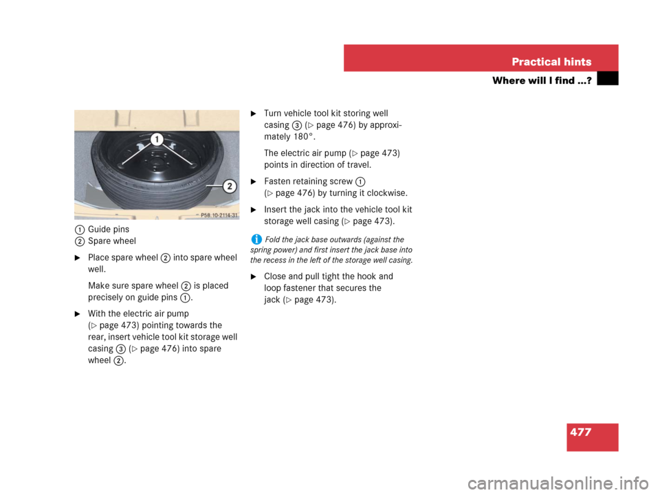
1Guide pins
2Spare wheel
�Place spare wheel 2 into spare wheel
well.
Make sure spare wheel 2 is placed
precisely on guide pins 1.
�With the electric air pump
(
�page 473) pointing towards the
rear, insert vehicle tool kit storage well
casing 3 (
�page 476) into spare
wheel 2.
�Turn vehicle tool kit storing well
casing3 (
�page 476) by approxi-
mately 180°.
The electric air pump (
�page 473)
points in direction of travel.
�Fasten retaining screw 1
(
�page 476) by turning it clockwise.
�Insert the jack into the vehicle tool kit
storage well casing (
�page 473).
�Close and pull tight the hook and
loop fastener that secures the
jack (
�page 473).
iFold the jack base outwards (against the
spring power) and first insert the jack base into
the recess in the left of the storage well casing.
Page 479 of 570

478 Practical hints
Unlocking / locking in an emergency
Unlocking the vehicle
If you cannot unlock the vehicle with the
SmartKey or KEYLESS-GO*, open the
driver’s door using the mechanical key.Removing the mechanical key
1Mechanical key locking tab
2Mechanical key
�Move locking tab1 in direction of
arrow.
�Slide mechanical key2 out of the
housing.Unlocking the driver’s door
1Unlocking
2Mechanical key
�Insert mechanical key 2 into the
driver’s door lock until it stops.
�Turn mechanical key 2 counterclock-
wise to position1 and hold it there.
�Pull the door handle until the locking
knob moves up.
The driver’s door is unlocked.
�Pull the door handle once more to open
the driver’s door.
iUnlocking the driver’s door with the
mechanical key will trigger the anti-theft
alarm system.
To cancel the alarm:
�Press buttonŒ or‹on the
SmartKey.
�Insert the SmartKey in the starter switch.
Vehicles with KEYLESS-GO*:
�Grasp an outside door handle.
The SmartKey with KEYLESS-GO must be
within 3 ft (1 m) of the vehicle.
�Press the KEYLESS-GO start / stop button
(
�page 41).
The SmartKey with KEYLESS-GO must be
inside the vehicle.
Page 481 of 570
480 Practical hints
Unlocking / locking in an emergency
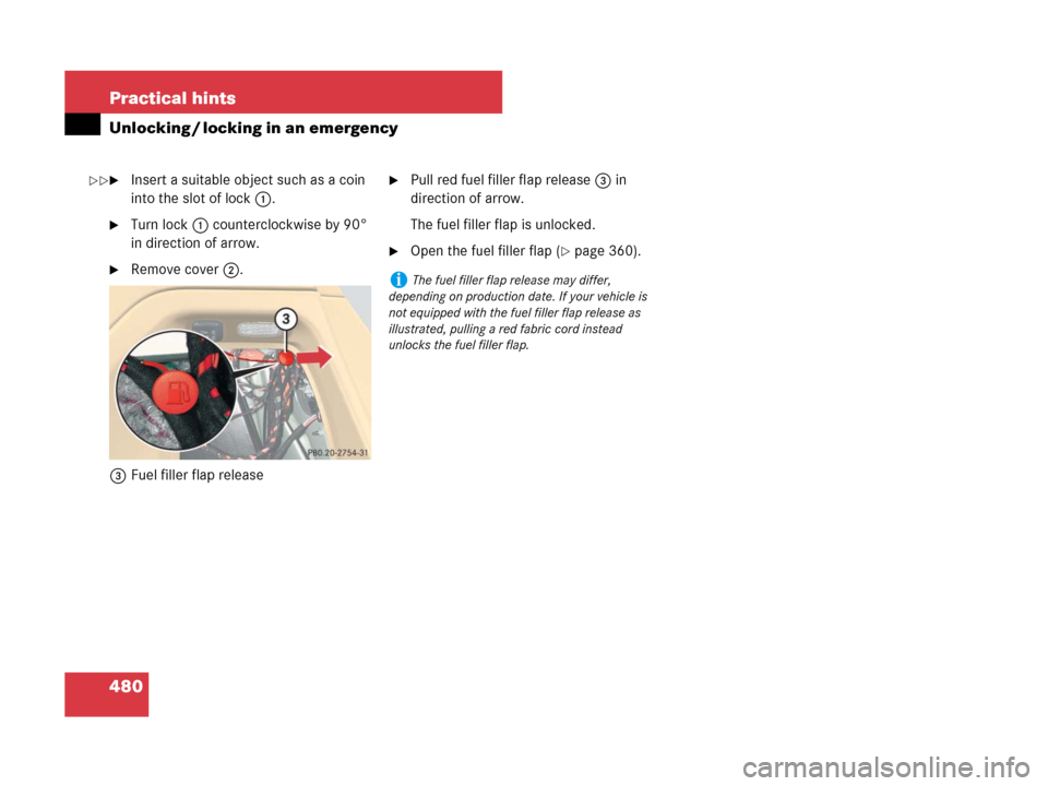
�Insert a suitable object such as a coin
into the slot of lock1.
�Turn lock1 counterclockwise by 90°
in direction of arrow.
�Remove cover2.
3Fuel filler flap release
�Pull red fuel filler flap release 3 in
direction of arrow.
The fuel filler flap is unlocked.
�Open the fuel filler flap (�page 360).
iThe fuel filler flap release may differ,
depending on production date. If your vehicle is
not equipped with the fuel filler flap release as
illustrated, pulling a red fabric cord instead
unlocks the fuel filler flap.
��
Page 482 of 570

481 Practical hints
Opening / closing in an emergency
�Opening / closing in an emergency
Power tilt/sliding sunroof*
You can open or close the tilt/sliding
sunroof manually should an electrical
malfunction occur.
The tilt/sliding sunroof drive is located
behind a cover on the overhead control
panel.
1Cover
�Remove the SmartKey from the starter
switch.Vehicles with KEYLESS-GO*:
�Turn off the engine by pressing the
KEYLESS-GO start/stop button
(
�page 67).
�Open the driver’s door (this puts
the starter switch to position0,
same as with the SmartKey
removed from starter switch).
The driver’s door can then be
closed again.
�Press on cover1 at the position
indicated by the arrow.
�Take off cover 1.
2Crank
�Take crank 2 out of the Operator’s
Manual pouch.
�Insert crank2 into hole.
�Turn crank2 clockwise to
�slide sunroof closed
�raise sunroof at the rear
�Turn crank2 counterclockwise to
�slide sunroof open
�lower sunroof at the rear
iTurn crank2 slowly and smoothly.
The tilt/sliding sunroof must be synchronized if
it has been operated manually (
�page 260).
iThe panorama roof with power tilt/sliding
panel* cannot be operated as described.
Contact Roadside Assistance or an authorized
Mercedes-Benz Light Truck Center.
Page 488 of 570
487 Practical hints
Replacing bulbs
Replacing bulbs for front lamps
Before you start to replace a bulb for a
front lamp, do the following first:
�Turn the exterior lamp switch to
positionM (
�page 146).
�Open the hood (�page 364).
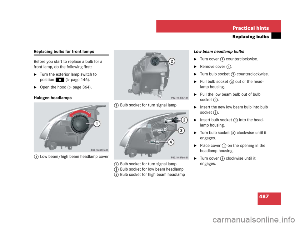
Halogen headlamps
1Low beam/high beam headlamp cover2Bulb socket for turn signal lamp
2Bulb socket for turn signal lamp
3Bulb socket for low beam headlamp
4Bulb socket for high beam headlampLow beam headlamp bulbs
�Turn cover 1 counterclockwise.
�Remove cover 1.
�Turn bulb socket 3 counterclockwise.
�Pull bulb socket 3 out of the head-
lamp housing.
�Pull the low beam bulb out of bulb
socket 3.
�Insert the new low beam bulb into bulb
socket 3.
�Insert bulb socket 3 into the head-
lamp housing.
�Turn bulb socket 3 clockwise until it
engages.
�Place cover 1 on the opening in the
headlamp housing.
�Turn cover 1 clockwise until it
engages.
Page 489 of 570
488 Practical hints
Replacing bulbs
High beam headlamp bulbs
�Turn cover 1 counterclockwise.
�Remove cover 1.
�Turn bulb socket 4 counterclockwise.
�Pull bulb socket 4 out of the head-
lamp housing.
�Pull the high beam bulb out of bulb
socket 4.
�Insert the new high beam bulb into bulb
socket 4.
�Insert bulb socket 4 into the head-
lamp housing.
�Turn bulb socket 4 clockwise until it
engages.
�Place cover 1 on the opening in the
headlamp housing.
�Turn cover 1 clockwise until it
engages.Front turn signal lamp bulbs
�Pull bulb socket 2 out of the head-
lamp housing.
�Pull the turn signal bulb out of bulb
socket 2.
�Insert the new turn signal bulb into bulb
socket 2.
�Insert bulb socket 2 into the head-
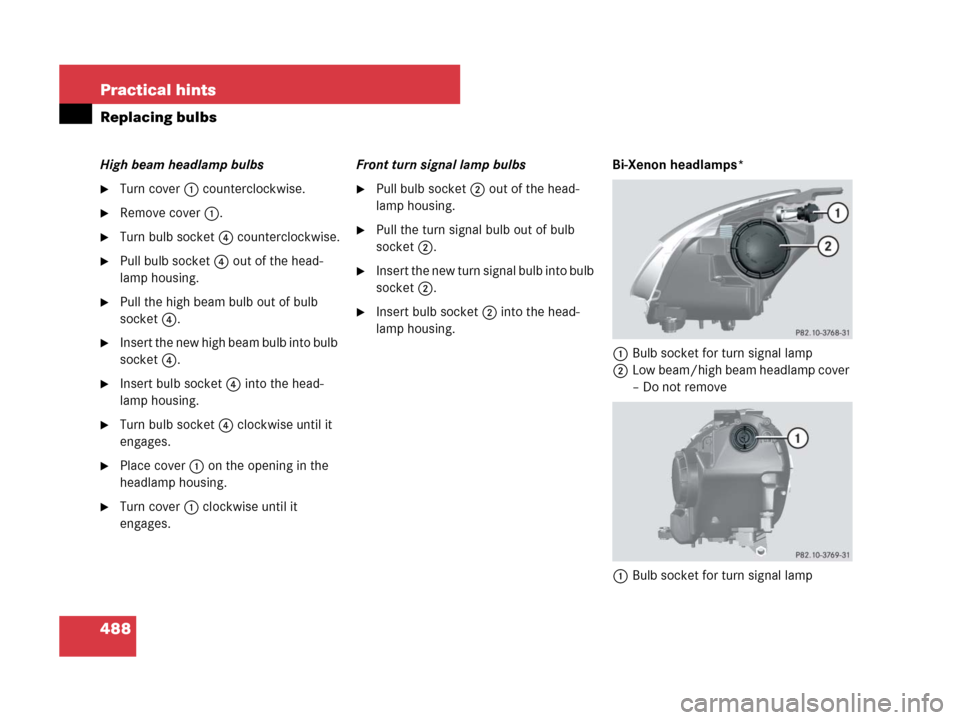
lamp housing.Bi-Xenon headlamps*
1Bulb socket for turn signal lamp
2Low beam/high beam headlamp cover
– Do not remove
1Bulb socket for turn signal lamp