Page 452 of 570
451 Practical hints
What to do if …
Symbol messages
Display symbolDisplay messagePossible cause/consequencePossible solution
#The battery is no longer charg-
ing.
Possible causes:
�alternator malfunctioning
�broken poly-V-belt
Do not forget that the brake
system requires electrical
energy and may be operating
with restricted capability.
Considerably greater brake
pedal force is required and the
stopping distance is increased.
�Stop in a safe location or as soon as it is
safe to do so and check the poly-V-belt.
If it is broken:
�Do not continue to drive. Otherwise
the engine will overheat due to an
inoperative water pump which may
result in damage to the engine.
Contact an authorized
Mercedes-Benz Light Truck Center.
If it is intact:
�Contact an authorized
Mercedes-Benz Light Truck Center
immediately. Adjust driving to be
consistent with reduced braking
responsiveness.
Page 454 of 570
453 Practical hints
What to do if …
Display symbolDisplay messagePossible cause/consequencePossible solution
;(USA only)
!(Canada only)
Release
parking brakeYou are driving with the parking
brake set.�Release the parking brake (�page 57).
;(USA only)
3(Canada only)
EBV, ABS, ESP inoperative
See Operator’s ManualThe EBP, the ABS, and the ESP®
have switched off due to a mal-
function. The BAS is also
switched off.
The brake system is still func-
tional but without the EBP, the
ABS, and the ESP
® available.
�Continue driving with added caution.
Wheels may lock during hard braking,
reducing steering capability.
�Have the system checked at an
authorized Mercedes-Benz Light Truck
Center as soon as possible.
Failure to follow these instructions increases
the risk of an accident.
Page 460 of 570

459 Practical hints
What to do if …
Display symbolDisplay messagePossible cause/consequencePossible solution
NEngine oil level
Stop car, turn engine offThere is no oil in the engine.
There is a danger of engine
damage.�Carefully bring the vehicle to a halt as
soon as it is safe to do so in a safe
location.
�Turn off the engine.
�Add engine oil (�page 369) and check
the engine oil level (
�page 366).
Engine oil level
Reduce oil levelYou have added too much
engine oil. There is a risk of
damaging the engine and/or the
catalytic converter (gasoline en-
gine) or the oxidation catalyst
(diesel engine).�Have oil siphoned or drained off.
Observe all legal requirements with
respect to its disposal.
Engine oil level
Visit workshopThe engine oil has dropped to a
critical level.�Check the engine oil level (�page 366)
and add oil as required (
�page 369).
�If you must add engine oil frequently, have
the engine checked for possible leaks.
!The engine oil level warnings should not be
ignored. Extended driving with the symbol dis-
played could result inserious engine damage that is not covered by the
Mercedes-Benz Limited Warranty.
Page 474 of 570
473 Practical hints
Where will I find ...?
3Securing hook
�Release securing hook 3 (located be-
low the floor handle) from holder.3Securing hook
4Cargo compartment floor, raised
5Upper cargo compartment lip
�Engage securing hook 3 on upper
cargo compartment lip 5.
You can now access the vehicle tool kit.
To remove the vehicle tool kit storage
well casing, proceed as described
on (
�page 476).6Wheel bolt wrench
7Electric air pump
8Jack
9Spare fuses, fuse extractor, fuse chart
aSpare wheel (collapsible tire)
bAlignment bolt
cTowing eye bolt
dCollapsible wheel chock
eSpare wheel bolts
fVehicle tool kit storage well casing
�To remove jack8, loosen the hook
and loop fastener.
!With the cargo compartment cover blind*
installed behind the third-row seats
(
�page 306), disengage cargo compartment
cover blind* and flip it forward. Otherwise the
strap of the securing hook could damage the
cargo compartment cover blind*.
Page 475 of 570

474 Practical hints
Where will I find ...?
Vehicle jackThe vehicle jack is located underneath the
storage compartment floor.
Storage position
�Remove vehicle jack from its storage
compartment (
�page 472).
�Push crank handle up.
Operational position
�Turn crank handle clockwise until it
engages (operational position).
Before storing the vehicle jack in its stor-
age compartment:
�The vehicle jack should be fully col-
lapsed.
�The handle must be folded in (storage
position).
Warning!G
The jack is designed exclusively for jacking
up the vehicle at the jack take-up brackets
built into both sides of the vehicle. To help
avoid personal injury, use the jack only to lift
the vehicle during a wheel change. Never
get beneath the vehicle while it is supported
by the jack. Keep hands and feet away from
the area under the lifted vehicle. Always
firmly set parking brake and block wheels
before raising vehicle with jack.
Do not disengage parking brake while the
vehicle is raised. Be certain that the jack is
always vertical (plumb line) when in use,
especially on hills. Always try to use the jack
on level surface.
Make sure the jack arm is fully seated in the
jack take-up bracket. Always lower the
vehicle onto sufficient capacity jackstands
before working under the vehicle.
Page 476 of 570

475 Practical hints
Where will I find ...?
Setting up the collapsible wheel chock
The collapsible wheel chock serves to ad-
ditionally secure the vehicle, e.g. while
changing the wheel.
1Tilt the plate upward
2Fold the lower plate outward
3Insert the plate�Tilt both plates upward1.
�Fold the lower plate outward2.
�Guide the tabs of the lower plate all the
way into the openings of base plate3.
For information on where to place wheel
chocks when changing a wheel, see “Lift-
ing the vehicle” (
�page 498).
Spare wheel
Warning!G
The dimensions of the spare wheel are
different from those of the road wheels. As
a result, the vehicle handling characteristics
change when driving with a spare wheel
mounted. Adapt your driving style accord-
ingly.
The spare wheel is for temporary use only.
When driving with a spare wheel mounted,
ensure proper tire inflation pressure and do
not exceed a vehicle speed of
50 mph (80 km/ h).
Drive to the nearest Mercedes-Benz Light
Truck Center as soon as possible to have the
spare wheel replaced with a regular road
wheel.
Never operate the vehicle with more than
one spare wheel mounted.
Do not switch off the ESP
® with a spare
wheel mounted.
Page 492 of 570

491 Practical hints
Replacing bulbs
�Turn bulb socket 5 counterclockwise.
�Pull bulb socket 5 out of the housing.
�Pull the bulb out of bulb socket 5.
�Insert the new corner-illuminating front
fog lamp bulb into bulb socket 5.
�Insert bulb socket 5 into the housing.
�Turn bulb socket 5 clockwise until it
engages.
�Insert corner-illuminating front fog
lamp 1 back into bumper.
�Fasten retaining screws4.
�Reinsert cover 2 and press it in until it
engages.
�Fasten retaining screw(s)3.Additional turn signal lamps bulbs
The additional turn signal lamps in the
exterior rear view mirrors have LEDs.
If a malfunction occurs or LEDs fail to
function, the entire turn signal unit must
be replaced. Have the turn signal unit re-
placed by an authorized Mercedes-Benz
Light Truck Center.
Front side marker lamp bulbs
Since replacing the side marker lamp bulbs
is a technically highly demanding process,
we recommend you have the side marker
lamp bulbs replaced by an authorized
Mercedes-Benz Light Truck Center.
Replacing bulbs for rear lamps
Before you start to replace a bulb for a rear
lamp, do the following first:
�Turn the combination switch to
positionM (
�page 146).
Tail lamp unit
�Open the tailgate (�page 123).
iTo access the tail lamp units, you have to
remove the cover in the corresponding side trim
panel of the cargo compartment.
Page 493 of 570
492 Practical hints
Replacing bulbs
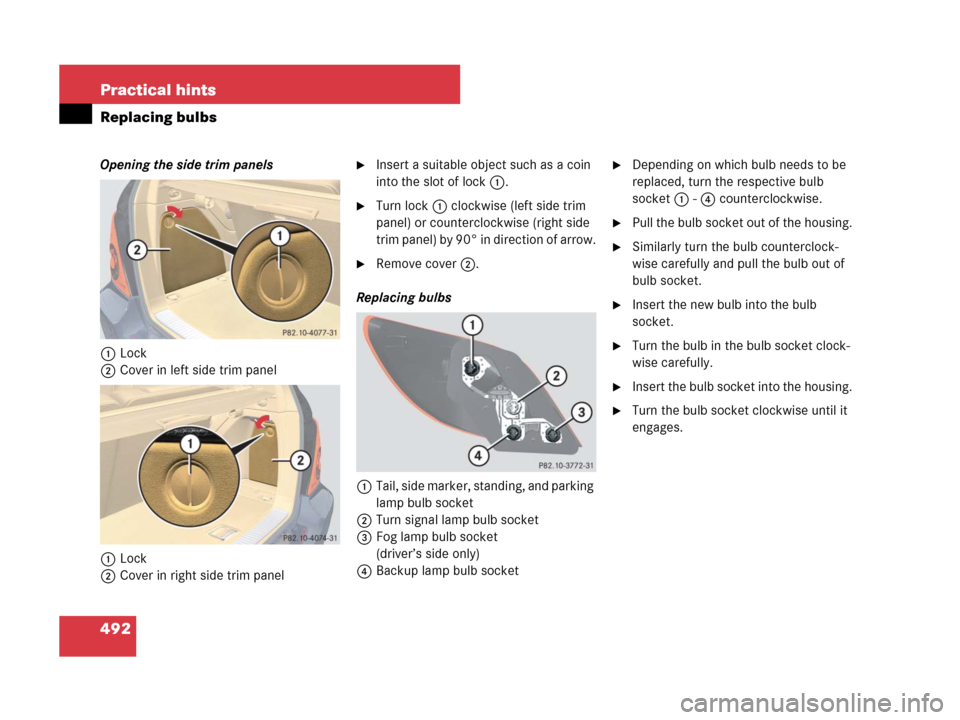
Opening the side trim panels
1Lock
2Cover in left side trim panel
1Lock
2Cover in right side trim panel�Insert a suitable object such as a coin
into the slot of lock1.
�Turn lock1 clockwise (left side trim
panel) or counterclockwise (right side
trim panel) by 90° in direction of arrow.
�Remove cover2.
Replacing bulbs
1Tail, side marker, standing, and parking
lamp bulb socket
2Turn signal lamp bulb socket
3Fog lamp bulb socket
(driver’s side only)
4Backup lamp bulb socket
�Depending on which bulb needs to be
replaced, turn the respective bulb
socket 1 - 4 counterclockwise.
�Pull the bulb socket out of the housing.
�Similarly turn the bulb counterclock-
wise carefully and pull the bulb out of
bulb socket.
�Insert the new bulb into the bulb
socket.
�Turn the bulb in the bulb socket clock-
wise carefully.
�Insert the bulb socket into the housing.
�Turn the bulb socket clockwise until it
engages.


!(Canada only)
Release
parking brakeYou are driving with the parking
brake s")