Page 301 of 595
300 Controls in detail
Loading
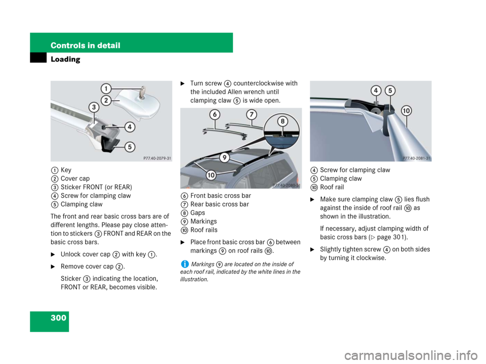
1Key
2Cover cap
3Sticker FRONT (or REAR)
4Screw for clamping claw
5Clamping claw
The front and rear basic cross bars are of
different lengths. Please pay close atten-
tion to stickers3 FRONT and REAR on the
basic cross bars.
�Unlock cover cap2 with key1.
�Remove cover cap2.
Sticker3 indicating the location,
FRONT or REAR, becomes visible.
�Turn screw4 counterclockwise with
the included Allen wrench until
clamping claw5 is wide open.
6Front basic cross bar
7Rear basic cross bar
8Gaps
9Markings
aRoof rails
�Place front basic cross bar6 between
markings9 on roof railsa.4Screw for clamping claw
5Clamping claw
aRoof rail
�Make sure clamping claw5 lies flush
against the inside of roof raila as
shown in the illustration.
If necessary, adjust clamping width of
basic cross bars (
�page 301).
�Slightly tighten screw4 on both sides
by turning it clockwise.
iMarkings9 are located on the inside of
each roof rail, indicated by the white lines in the
illustration.
Page 302 of 595
301 Controls in detail
Loading
�Place rear basic cross bar7 on roof
railsa i n s u c h a w a y t h a t t h e c l a m p i n g
claws reach into gaps8 (
�page 300)
on the roof rails.
�Make sure clamping claw5 lies flush
against the inside of roof raila as
shown in the illustration (
�page 300).
If necessary, adjust clamping width of
basic cross bars (
�page 301).
�Slightly tighten screw4 on both sides
by turning it clockwise.
�On the front and rear basic cross bars
tighten screws4. Observe a
tightening torque of 4 lb-ft (6 Nm).
�Attach cover caps (�page 300) and
lock them.
�Store key and Allen wrench back into
the storage well (
�page 495).
Adjusting the clamping widths of the
basic cross barsThe clamping widths of the basic cross
bars are factory set for your vehicle. These
clamping widths are solely intended for the
designated positions.
Only install the basic cross bars at the des-
ignated locations and pay attention to the
stickers3 FRONT and REAR
(
�page 300).
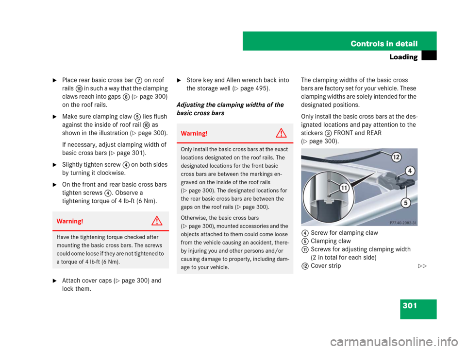
4Screw for clamping claw
5Clamping claw
bScrews for adjusting clamping width
(2 in total for each side)
cCover strip
Warning!G
Have the tightening torque checked after
mounting the basic cross bars. The screws
could come loose if they are not tightened to
a torque of 4 lb-ft (6 Nm).
Warning!G
Only install the basic cross bars at the exact
locations designated on the roof rails. The
designated locations for the front basic
cross bars are between the markings en-
graved on the inside of the roof rails
(
�page 300). The designated locations for
the rear basic cross bars are between the
gaps on the roof rails (
�page 300).
Otherwise, the basic cross bars
(
�page 300), mounted accessories and the
objects attached to them could come loose
from the vehicle causing an accident, there-
by injuring you and other persons and/or
causing damage to property, including dam-
age to your vehicle.
��
Page 304 of 595
303 Controls in detail
Loading
�Attach add-on roof equipment to the
basic cross bars.
�Place cover stripc flush against the
add-on roof equipment, and mark the
end of basic cross bar on cover strip.
�Cut off cover stripc at marked loca-
tion.
�Press cover stripc piece by piece into
groove of the basic cross bar.
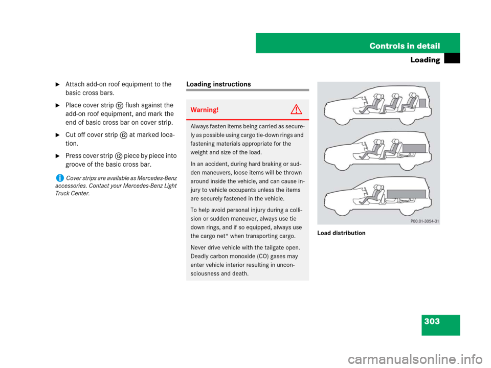
Loading instructions
Load distribution
iCover strips are available as Mercedes-Benz
accessories. Contact your Mercedes-Benz Light
Truck Center.
Warning!G
Always fasten items being carried as secure-
ly as possible using cargo tie-down rings and
fastening materials appropriate for the
weight and size of the load.
In an accident, during hard braking or sud-
den maneuvers, loose items will be thrown
around inside the vehicle, and can cause in-
jury to vehicle occupants unless the items
are securely fastened in the vehicle.
To help avoid personal injury during a colli-
sion or sudden maneuver, always use tie
down rings, and if so equipped, always use
the cargo net* when transporting cargo.
Never drive vehicle with the tailgate open.
Deadly carbon monoxide (CO) gases may
enter vehicle interior resulting in uncon-
sciousness and death.
Page 307 of 595
306 Controls in detail
Loading
Hooks
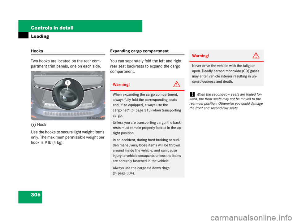
Two hooks are located on the rear com-
partment trim panels, one on each side.
1Hook
Use the hooks to secure light weight items
only. The maximum permissible weight per
hook is 9 lb (4 kg).Expanding cargo compartment
You can separately fold the left and right
rear seat backrests to expand the cargo
compartment.
Warning!G
When expanding the cargo compartment,
always fully fold the corresponding seats
and, if so equipped, always use the
cargo net* (
�page 313) when transporting
cargo.
Unless you are transporting cargo, the back-
rests must remain properly locked in the up-
right position.
In an accident, during hard braking or sud-
den maneuvers, loose items will be thrown
around inside the vehicle, and can cause
injury to vehicle occupants unless the items
are securely fastened in the vehicle.
Always use the cargo tie down rings
(
�page 304).
Warning!G
Never drive the vehicle with the tailgate
open. Deadly carbon monoxide (CO) gases
may enter vehicle interior resulting in un-
consciousness and death.
!When the second-row seats are folded for-
ward, the front seats may not be moved to the
rearmost position. Otherwise you could damage
the front and second-row seats.
Page 321 of 595
320 Controls in detail
Useful features
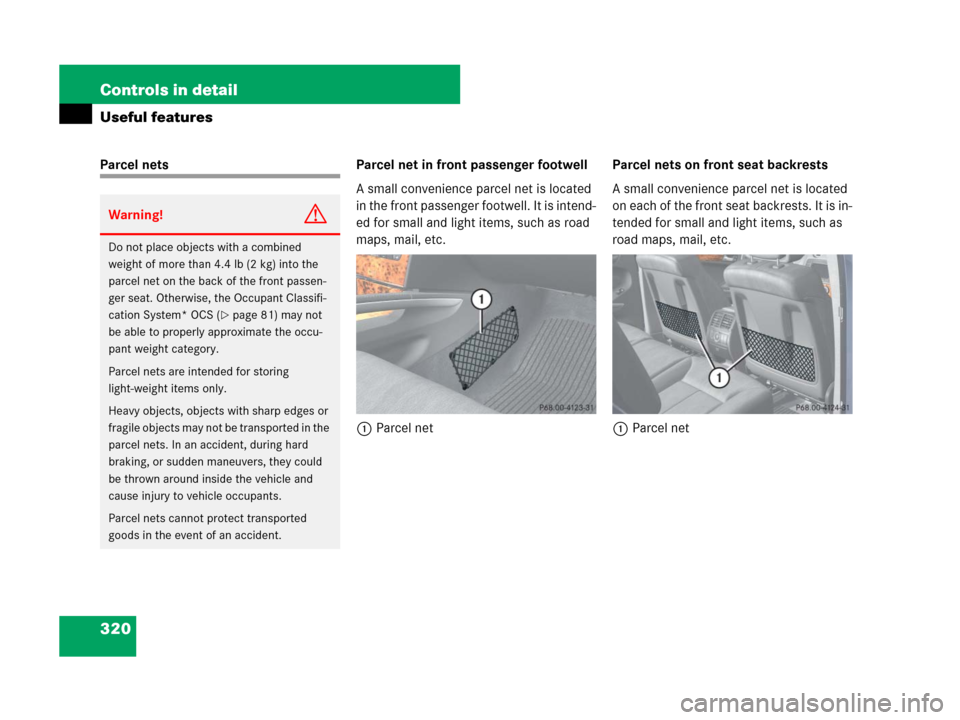
Parcel nets Parcel net in front passenger footwell
A small convenience parcel net is located
in the front passenger footwell. It is intend-
ed for small and light items, such as road
maps, mail, etc.
1Parcel netParcel nets on front seat backrests
A small convenience parcel net is located
on each of the front seat backrests. It is in-
tended for small and light items, such as
road maps, mail, etc.
1Parcel net
Warning!G
Do not place objects with a combined
weight of more than 4.4 lb (2 kg) into the
parcel net on the back of the front passen-
ger seat. Otherwise, the Occupant Classifi-
cation System* OCS (
�page 81) may not
be able to properly approximate the occu-
pant weight category.
Parcel nets are intended for storing
light-weight items only.
Heavy objects, objects with sharp edges or
fragile objects may not be transported in the
parcel nets. In an accident, during hard
braking, or sudden maneuvers, they could
be thrown around inside the vehicle and
cause injury to vehicle occupants.
Parcel nets cannot protect transported
goods in the event of an accident.
Page 323 of 595
322 Controls in detail
Useful features
Cup holders in third-row side trim
Cup holders are located in the side trims of
the third-row seats.
1Cup holderRemoving and reinstalling cup holder
The front cup holder can be removed for
cleaning purposes.
1Cup holder
2Bridge with card, ticket holder
�Hold cup holder at its bridge2 and
pull out bridge in direction of arrow.
�Pull cup holder1 out in direction of ar-
row.
�First, insert the cup holder1 and then
insert bridge2.
Ashtrays*
Your vehicle is equipped with an ashtray
and a cigarette lighter (
�page 324) locat-
ed in the front center console and an ash-
tray located in front of the second-row
seats (
�page 323).
Ashtray in the center console
1Ashtray insert
2Cover plate
iIf your vehicle is not equipped with a smok-
ing package*, it has a storage compartment
(
�page 318) with a power outlet (�page 325)
instead.
Page 324 of 595
323 Controls in detail
Useful features
Opening the ashtray
�Briefly touch cover plate2.
The ashtray opens automatically.
Removing ashtray insert
�Grip the ashtray insert1 on the sides
and pull it out upwards.
Reinstalling ashtray insert
�Install ashtray insert1.
�Close ashtray cover plate2.Rear center console ashtray
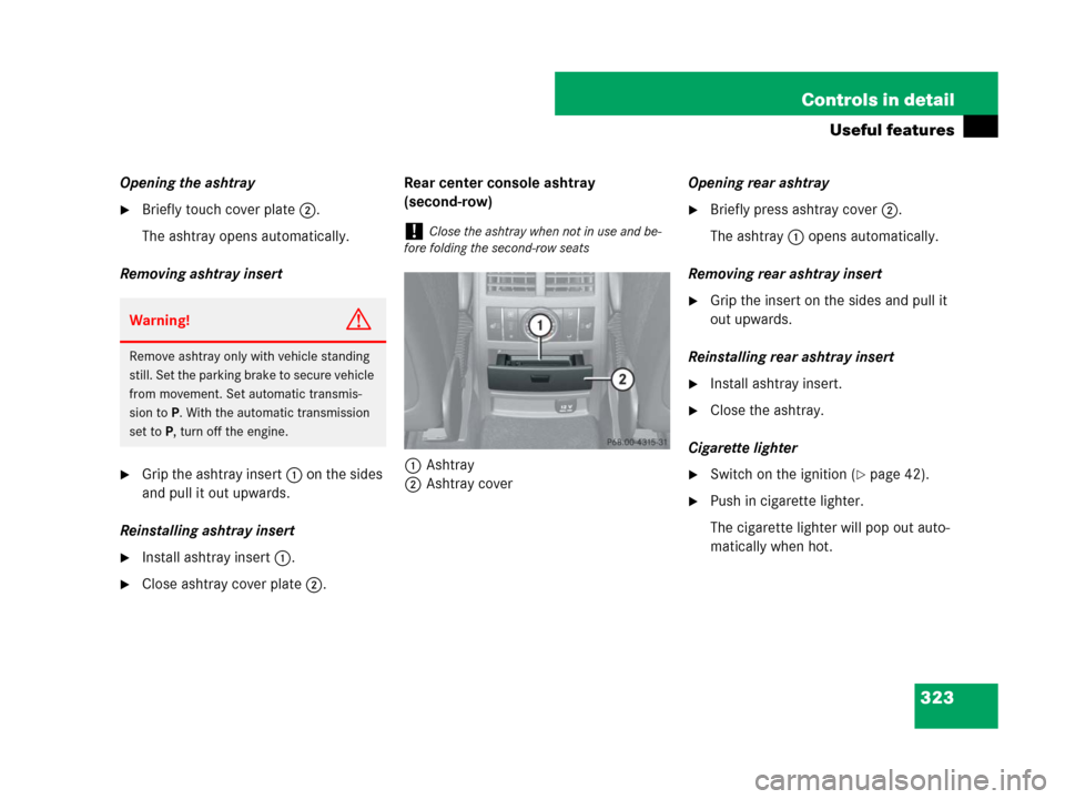
(second-row)
1Ashtray
2Ashtray coverOpening rear ashtray
�Briefly press ashtray cover2.
The ashtray1 opens automatically.
Removing rear ashtray insert
�Grip the insert on the sides and pull it
out upwards.
Reinstalling rear ashtray insert
�Install ashtray insert.
�Close the ashtray.
Cigarette lighter
�Switch on the ignition (�page 42).
�Push in cigarette lighter.
The cigarette lighter will pop out auto-
matically when hot.
Warning!G
Remove ashtray only with vehicle standing
still. Set the parking brake to secure vehicle
from movement. Set automatic transmis-
sion toP. With the automatic transmission
set toP, turn off the engine.
!Close the ashtray when not in use and be-
fore folding the second-row seats
Page 325 of 595
324 Controls in detail
Useful features
Cigarette lighter*
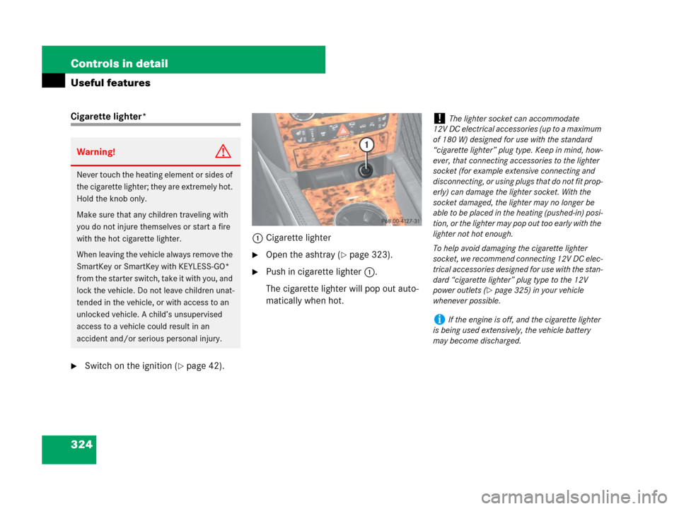
�Switch on the ignition (�page 42).1Cigarette lighter
�Open the ashtray (�page 323).
�Push in cigarette lighter1.
The cigarette lighter will pop out auto-
matically when hot.
Warning!G
Never touch the heating element or sides of
the cigarette lighter; they are extremely hot.
Hold the knob only.
Make sure that any children traveling with
you do not injure themselves or start a fire
with the hot cigarette lighter.
When leaving the vehicle always remove the
SmartKey or SmartKey with KEYLESS-GO*
from the starter switch, take it with you, and
lock the vehicle. Do not leave children unat-
tended in the vehicle, or with access to an
unlocked vehicle. A child’s unsupervised
access to a vehicle could result in an
accident and/or serious personal injury.
!The lighter socket can accommodate
12V DC electrical accessories (up to a maximum
of 180 W) designed for use with the standard
“cigarette lighter” plug type. Keep in mind, how-
ever, that connecting accessories to the lighter
socket (for example extensive connecting and
disconnecting, or using plugs that do not fit prop-
erly) can damage the lighter socket. With the
socket damaged, the lighter may no longer be
able to be placed in the heating (pushed-in) posi-
tion, or the lighter may pop out too early with the
lighter not hot enough.
To help avoid damaging the cigarette lighter
socket, we recommend connecting 12V DC elec-
trical accessories designed for use with the stan-
dard “cigarette lighter” plug type to the 12V
power outlets (
�page 325) in your vehicle
whenever possible.
iIf the engine is off, and the cigarette lighter
is being used extensively, the vehicle battery
may become discharged.