Page 80 of 595

79 Safety and Security
Occupant safety
When you sell your vehicle we strongly
urge you to give notice to the subsequent
owner that it is equipped with an SRS by
alerting them to the applicable section in
the Operator’s Manual.Front air bags
1Driver air bag
2Passenger air bag
Driver and front passenger front air bags
are deployed:
�in the event of certain frontal impacts
�if impact exceeds a preset deployment
threshold
�independently of the side impact air
bags
Warning!G
Only use seat covers which have been
tested and approved by Mercedes-Benz for
your vehicle model. Using other seat covers
may interfere with or prevent the
deployment of the front side impact air bags
or the rear side impact air bags*. Contact an
authorized Mercedes-Benz Light Truck
Center for availability.
iThe front air bags in this vehicle have been
designed to inflate in two stages. This allows the
air bag to have different rates of inflation that are
based on the rate of relevant vehicle decelera-
tion as assessed by the air bag control unit.
Vehicles with OCS* only:
On the front passenger-side, the front air bag
deployment is additionally influenced by the
passenger’s weight category as identified by the
Occupant Classification System (OCS)
(
�page 81).
Vehicles with OCS* only:
The lighter the front passenger side occupant,
the higher the vehicle deceleration rate required
for the second stage inflation of the air bag.
Page 114 of 595
113 Controls in detail
Locking and unlocking
Seats
Memory function*
Lighting
Instrument cluster
Control system
Automatic transmission
Transfer case
Differential locks*
Good visibility
Climate control
3-zone automatic climate control*
Power windows
Power tilt/sliding sunroof*
Driving systems
Loading
Useful features
Page 115 of 595

114 Controls in detail
In the “Controls in detail” section you will
find detailed information on how to oper-
ate the equipment installed in your vehicle.
If you are already familiar with the basic
functions of your vehicle, this section will
be of particular interest to you.
To quickly familiarize yourself with the ba-
sic functions of the vehicle, refer to the
“Getting started” section of this manual.
The corresponding page numbers are
given at the beginning of each segment.
Locking and unlocking
For more information on locking and un-
locking, see the “Getting started” section
(
�page 40) and (�page 71).
SmartKey
Your vehicle comes supplied with two
SmartKeys, each with remote control and a
removable mechanical key.
The locking tabs for the mechanical key
portion of the two SmartKeys are a differ-
ent color to help distinguish each
SmartKey unit.
The SmartKey provides an extended oper-
ating range. To prevent theft, however, it is
advisable to only unlock the vehicle when
you are in close proximity to it.
The SmartKey centrally locks and unlocks:
�the doors
�the tailgate
�the fuel filler flap
SmartKey with remote control
1‹ Lock button
2Š Unlock button* for tailgate
3Locking tab for mechanical key
4ΠUnlock button
5Battery check lamp
6Â Panic button (
�page 102)
Page 118 of 595

117 Controls in detail
Locking and unlocking
Global locking
�Press button‹.
With the tailgate and all doors closed,
the turn signal lamps flash three times.
The locking knobs in the doors move
down. The anti-theft alarm system is
armed.
Restoring to factory setting
�Press and hold buttonsŒ and‹
simultaneously for about 5 seconds
until battery check lamp5
(
�page 114) flashes twice.
SmartKey with KEYLESS-GO*
Vehicles equipped with KEYLESS-GO come
with two SmartKeys with KEYLESS-GO,
each with remote control and a removable
mechanical key.
The locking tabs for the mechanical key
portion of the two SmartKeys with
KEYLESS-GO are a different color to help
distinguish each SmartKey with
KEYLESS-GO unit.
The KEYLESS-GO function is integrated
into the SmartKey. On these vehicles, the
validity of the SmartKey with KEYLESS-GO
is checked when you grasp an outside door
handle.
If the SmartKey with KEYLESS-GO is valid,
your vehicle unlocks
�the doors
�the tailgate
�the fuel filler flap
SmartKey with KEYLESS-GO*
1‹ Lock button
2Š Unlock button* for tailgate
3Locking tab for mechanical key
4ΠUnlock button
5Battery check lamp
6Â Panic button (
�page 102)
Page 137 of 595
The seat backrest tilt can be set to five
different positions.
The handles for adjusting the seats are
located")
136 Controls in detail
Seats
Rear seat adjustment
Seat backrest tilt (second-row seats)The seat backrest tilt can be set to five
different positions.
The handles for adjusting the seats are
located on the rear of each seat base.
1Adjustment handle
�While seated, pull handle1 in direc-
tion of arrow to resistance point and
hold it there.
�To move seat backrest back, lean light-
ly against backrest.
Warning!G
Never ride in a moving vehicle with the seat
backrest in an excessively reclined position
as this can be dangerous. You could slide
under the seat belt in a collision. If you slide
under it, the belt would apply force at the ab-
domen or neck. That could cause serious or
fatal injuries. The seat backrest and seat
belts provide the best restraint when the
wearer is in a nearly upright position and
belts are properly positioned on the body.
Your seat must be adjusted so that you can
correctly fasten your seat belt (
�page 54).
Never place hands under the seat or near
any moving parts while a seat is being
adjusted.
After adjusting rear seats, make sure
�the seats are properly locked
�the seat backrests are in an upright po-
sition and are properly locked
Check for secure locking by pushing and
pulling on the seat backrests. If a seat and
seat backrest are not properly locked, the
seat could move forward and the seat back-
rest could fold. The child seat would no long-
er be properly supported or positioned to
provide its intended benefit.
Warning!G
The seat belt only offers its intended protec-
tion when the seat backrest is in a nearly
vertical position and the occupant is sitting
upright. Avoid sitting in positions that pre-
vent the seat belt from being properly posi-
tioned against the body (
�page 54). You
should therefore adjust the backrest to a po-
sition as upright as possible.
Page 144 of 595

143 Controls in detail
Memory function*
�Memory function*
Prior to operating the vehicle, the driver
should check and adjust the seat height,
seat position fore and aft, and seat back-
rest angle if necessary, to ensure adequate
control, reach and comfort. The head
restraint should also be adjusted for
proper height. See also the section on
air bags (
�page 76) for proper seat posi-
tioning.
In addition, adjust the steering wheel to
ensure adequate control, reach, operation
and comfort. Both the interior and exterior
rear view mirrors should be adjusted for
adequate rear vision.
Fasten seat belts. Infants and small chil-
dren should be seated in a properly se-
cured restraint system that complies with
U.S. Federal Motor Vehicle Safety Stan-
dards 213 and 225 and Canadian Motor
Vehicle Safety Standards 213 and 210.2.With the memory function you can store up
to three different configurations.
Each stored position on the driver’s side
includes the following settings:
�Seat position
�Multicontour seat*: previously saved
setting
�Steering wheel position
�Exterior rear view mirrors’ positionEach stored position on the passenger side
includes the following settings:
�Seat position
�Multicontour seat*: previously saved
setting
Warning!G
Do not activate the memory function while
driving. Activating the memory function
while driving could cause the driver to lose
control of the vehicle.
Page 162 of 595
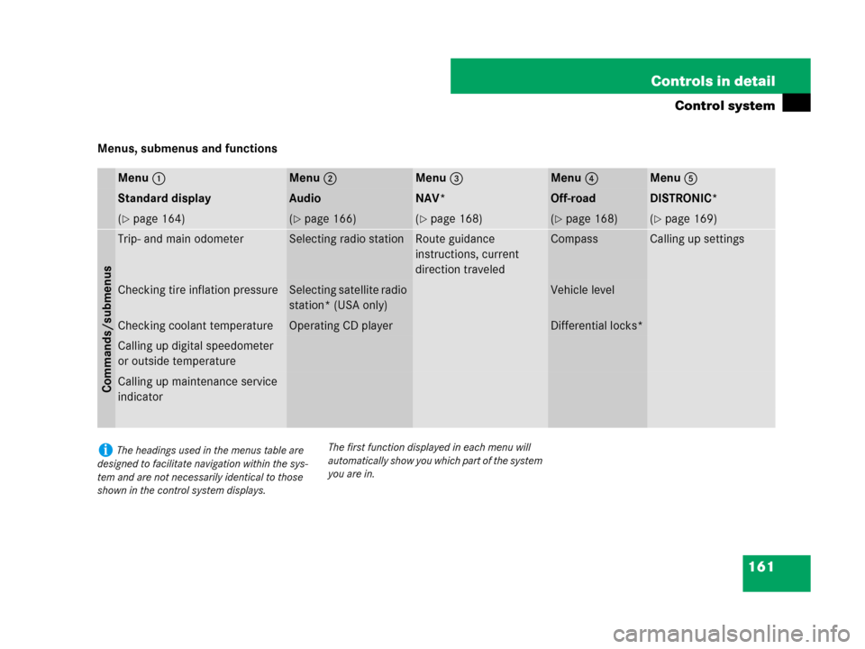
161 Controls in detail
Control system
Menus, submenus and functions
Menu1Menu2Menu3Menu4Menu5
Standard displayAudioNAV*Off-roadDISTRONIC*
(�page 164)(�page 166)(�page 168)(�page 168)(�page 169)
Commands/submenus
Trip- and main odometerSelecting radio stationRoute guidance
instructions, current
direction traveledCompassCalling up settings
Checking tire inflation pressureSelecting satellite radio
station* (USA only)Vehicle level
Checking coolant temperatureOperating CD playerDifferential locks*
Calling up digital speedometer
or outside temperature
Calling up maintenance service
indicator
iThe headings used in the menus table are
designed to facilitate navigation within the sys-
tem and are not necessarily identical to those
shown in the control system displays.The first function displayed in each menu will
automatically show you which part of the system
you are in.
Page 169 of 595

168 Controls in detail
Control system
NAV* menu
The
Nav menu contains the functions
needed to operate your navigation system.
�Press buttonè orÿ repeatedly
until the message
Nav appears in the
multifunction display.
The message shown in the multifunction
display depends on the status of the navi-
gation system:
�With the COMAND system switched
off, the message
Nav off appears in
the multifunction display.
�With the COMAND system switched on
but route guidance not activated, the
direction of travel and, if applicable, the
name of the street currently traveled
on appear in the multifunction display.
�With the COMAND system switched on
and route guidance activated, the di-
rection of travel and maneuver instruc-
tions appear in the multifunction
display.
Please refer to the COMAND system
manual for instructions on how to activate
the route guidance system.
Off-road menu
The Off-road menu displays the messages
for air suspension, differential locks* and
the direction into which you are currently
driving.
�Press buttonè orÿ repeatedly
until one of the following messages ap-
pears in the multifunction display.Vehicles with air suspension:
Vehicles with air suspension and
differential locks*:�Press buttonk orj repeatedly
until the desired setting is found.
For information on air suspension, see “Air
suspension package” (
�page 280).
For information on differential locks*, see
“Differential locks*” (
�page 206).
For information on the compass, see
“Vehicle submenu” (
�page 181) and
“Compass” (
�page 345).