Page 269 of 522
268 Controls in detailDriving systemsThe button is located in the lower section
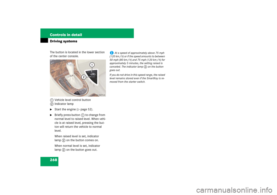
of the center console.
1Vehicle level control button
2Indicator lamp �
Start the engine (
�page 52).
�
Briefly press button1 to change from
normal level to raised level. When vehi-
cle is at raised level, pressing the but-
ton will return the vehicle to normal
level.
When raised level is set, indicator
lamp2 on the button comes on.
When normal level is set, indicator
lamp2 on the button goes out.
i
At a speed of approximately above 75 mph
(120 km / h) or if the speed amounts to between
50 mph (80 km / h) and 75 mph (120 km / h) for
approximately 5 minutes, the setting raised is
canceled. The indicator lamp 2 on the button
goes out.
If you do not drive in this speed range, the raised
level remains stored even if the SmartKey is re-
moved from the starter switch.
Page 270 of 522
*
The Parktronic system is an electronic aid
designed to assist the driver during park-
ing maneuvers. It visually and audibly")
269 Controls in detail
Driving systems
Parktronic system (Parking assist)*
The Parktronic system is an electronic aid
designed to assist the driver during park-
ing maneuvers. It visually and audibly indi-
cates the relative distance between the
vehicle and an obstacle.
The Parktronic system is automatically ac-
tivated when you switch on the ignition, re-
lease the parking brake, and placed the
gear selector lever in positionD,R,orN.
The Parktronic system deactivates at
speeds over approximately 11 mph
(18 km/h). At lower speeds the Parktronic
system turns on again.
The Parktronic system also deactivates
when you place the gear selector lever in
positionP or depress the parking brake
pedal.The Parktronic system monitors the sur-
roundings of your vehicle with six sensors
in the front bumper and four sensors in the
rear bumper.
1Sensors in the front bumper
Range of the sensors
To function properly, the sensors must be
free of dirt, ice, snow and slush. Clean the
sensors regularly, being careful not to
scratch or damage the sensors, see
“Cleaning the Parktronic system* sensors”
(
�page 373).
Warning!
G
Parktronic is a supplemental system. It is
not intended to, nor does it replace, the
need for extreme care. The responsibility
during parking and other critical maneuvers
always rests with the driver.
Special attention must be paid to objects
with smooth surfaces or low silhouettes
(e.g. trailer couplings, painted posts, or road
curbs). Such objects may not be detected by
the system and can damage the vehicle.
The operational function of the Parktronic
system can be affected by dirty sensors, es-
pecially at times of snow and ice, see
“Cleaning the Parktronic system* sensors”
(�page 373).
Interference caused by other ultrasonic sig-
nals (e.g. working jackhammers, car wash or
the air brakes of trucks) can cause the sys-
tem to send erratic indications, and should
be taken into consideration.
Warning!
G
Make sure no persons or animals are in the
area in which you are maneuvering. You
could otherwise injure them.
Page 271 of 522
270 Controls in detailDriving systems
Front sensors
Rear sensorsMinimum distance
If the system detects an obstacle in this
range, all the distance warning segments
illuminate and you hear a warning signal. If
the obstacle is closer than the minimum
distance, the actual distance might no
longer be indicated by the system.Center
approx. 40 in (100 cm)
Corners
approx. 24 in (60 cm)
Center
approx. 48 in (120 cm)
Corners
approx. 32 in (80 cm)
!
During parking maneuvers, pay special at-
tention to objects located above or below the
height of the sensors (e.g. planters or trailer
hitches). The Parktronic system will not detect
such objects at close range and damage to your
vehicle or the object may result.
Ultrasonic signals from outside sources (e.g.
truck air brakes, car wash or jackhammers) may
impair the operation of the Parktronic system.
Center
approx. 8in (20cm)
Corners
approx. 6in (15cm)
Page 272 of 522

271 Controls in detail
Driving systems
Warning indicators
Visual signals indicate to the driver the rel-
ative distance between the sensors and an
obstacle. The warning indicator for the
front area is located above the center air
vents in the dashboard. The warning indi-
cator for the rear area is integrated in the
rear trim.Front area warning indicator1Left side of the vehicle
2Right side of the vehicle
3Readiness indicatorsEach warning indicator is divided into five
yellow and two red segments for either
side of the vehicle. The Parktronic system
is operational when the yellow readiness
indicators3 are illuminated.
The position of the gear selector lever de-
termines which warning indicators will be
activated.
As your vehicle approaches an object, one
or more segments will come on, depending
on the distance. When the seventh seg-
ment illuminates, you have reached the
minimum distance.
�
Front area: An intermittent acoustic
warning will sound as the first red dis-
tance segment illuminates and a con-
stant acoustic warning lasting a
maximum of 2 seconds will sound for
the second red distance segment. The
signal is canceled when the gear selec-
tor lever is placed in positionP or the
parking brake is activated.
�
Rear area: An intermittent acoustic
warning will sound as the first red dis-
tance segment illuminates and a con-
stant acoustic warning lasting a
maximum of 2 seconds will sound for
the second red distance segment. The
signal is canceled when the gear selec-
tor lever is placed in position D,P or
the parking brake is activated.
Gear selector
lever position
Warning indicator
D
Front area activated
R or N
Front and rear area
activated
P
Neither activated
Page 273 of 522

272 Controls in detailDriving systemsSwitching the Parktronic system
on/off
The Parktronic system can be switched off
manually.
The Parktronic switch is located in the low-
er part of the center console (
�page 30).
1Parktronic switch
2Indicator lampSwitching off the Parktronic system
�
Press Parktronic switch 1.
Indicator lamp 2 comes on.
Switching on the Parktronic system
�
Press Parktronic switch 1 again.
Indicator lamp 2 goes out.
Parktronic system malfunction
If only the red distance segments illumi-
nates and an acoustic warning sounds,
there is a malfunction in the Parktronic
system. The Parktronic system will auto-
matically switch off after 20 seconds and
the indicator lamp in the Parktronic switch
comes on.
�
Have the Parktronic system checked
by an authorized Mercedes-Benz Cen-
ter as soon as possible.If only the red distance segments illumi-
nates and no acoustic warning sounds, the
Parktronic system sensors are dirty or
there is an interference from other radio or
ultrasonic signals. The Parktronic system
will automatically switch off after 20 sec-
onds and the indicator lamp in the
Parktronic switch comes on.
�
Switch off the ignition (
�page 37).
�
Clean the Parktronic system sensors
(�page 373).
�
Switch on the ignition (
�page 37).
or
�
Check the Parktronic system operation
at another location to rule out interfer-
ence from outside radio or ultrasonic
signals.
i
The Parktronic system is automatically
switched on when the ignition is switched on
(
�page 37).
Page 274 of 522
273 Controls in detail
Loading
�Loading
Roof rack*
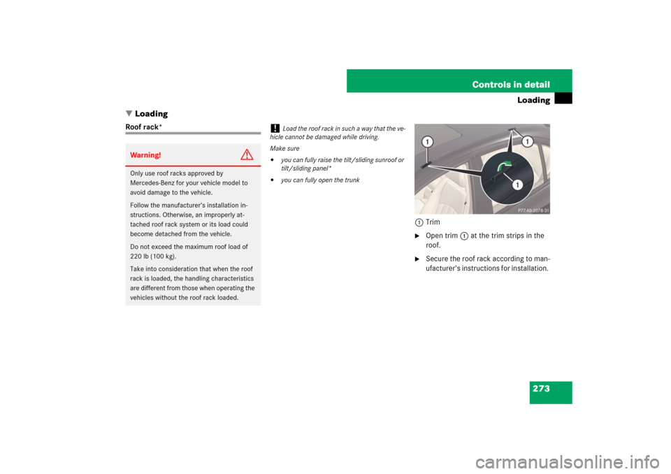
1Trim
�
Open trim1 at the trim strips in the
roof.
�
Secure the roof rack according to man-
ufacturer’s instructions for installation.
Warning!
G
Only use roof racks approved by
Mercedes-Benz for your vehicle model to
avoid damage to the vehicle.
Follow the manufacturer’s installation in-
structions. Otherwise, an improperly at-
tached roof rack system or its load could
become detached from the vehicle.
Do not exceed the maximum roof load of
220 lb (100 kg).
Take into consideration that when the roof
rack is loaded, the handling characteristics
are different from those when operating the
vehicles without the roof rack loaded.
!
Load the roof rack in such a way that the ve-
hicle cannot be damaged while driving.
Make sure
�
you can fully raise the tilt/sliding sunroof or
tilt/sliding panel*
�
you can fully open the trunk
Page 275 of 522
274 Controls in detailLoadingSki bag* (Canada only)
Unfolding and loading
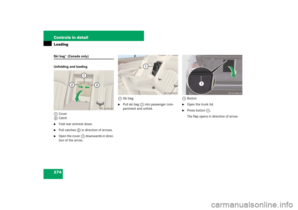
1Cover
2Catch�
Fold rear armrest down.
�
Pull catches2 in direction of arrows.
�
Open the cover1 downwards in direc-
tion of the arrow.1Ski bag
�
Pull ski bag1 into passenger com-
partment and unfold.1Button
�
Open the trunk lid.
�
Press button1.
The flap opens in direction of arrow.
Page 276 of 522
275 Controls in detail
Loading
�
From trunk, slide skis into ski bag.1Strap
�
Tighten strap1 by pulling at the loose
end (arrow) until the skis in the ski bag
are tightly secured.1Hook
2Eye
�
Connect hook1 of front strap to
eye2 located on center tunnel in
front of rear seat bench.
�
Tighten strap by pulling at the loose
end (arrow).
Warning!
G
The ski bag is designed for up to four pairs
of skis. Do not load the ski bag with other
objects.
Always fasten the ski bag securely. In an ac-
cident, an unfastened ski bag can cause in-
jury to vehicle occupants.