Page 437 of 522
436 Practical hintsUnlocking/locking in an emergencyUnlocking the vehicle
If you cannot unlock the vehicle with the
SmartKey or SmartKey with
KEYLESS-GO*, open the driver’s door and
the trunk using the mechanical key.
Removing the mechanical key
1Mechanical key locking tab
2Mechanical key
�
Move locking tab1 in direction of ar-
row.
�
Slide mechanical key2 out of the
housing.
Unlocking the driver’s door
�
Insert mechanical key2 into the
driver’s door lock until it stops.
�
Turn mechanical key2 counterclock-
wise to position1 until the locking
knobs move up.
The driver’s door is unlocked.
�
Pull door handle to open the driver’s
door.
i
Unlocking your vehicle with the mechanical
key and opening the driver’s door or the trunk
will trigger the anti-theft alarm system.
To cancel the alarm, Insert the SmartKey or
SmartKey with KEYLESS-GO* in the starter
switch.
1
Unlocking
2
Mechanical key
Page 438 of 522
 is required to open the trunk lid. �
Insert the mechanical key1 into the
trun")
437 Practical hints
Unlocking/locking in an emergency
Unlocking the trunk
A minimum height clearance of 5.90 ft
(1.80 m) is required to open the trunk lid. �
Insert the mechanical key1 into the
trunk lid lock until it stops.
�
Turn the mechanical key1 counter-
clockwise to position2 and hold it in
this position.
�
Pull the handle3 and lift the trunk lid.
The trunk opens.
�
Turn the mechanical key1 back and
remove it from the trunk lid lock.
Locking the vehicle
If you are unable to lock the vehicle with
the SmartKey or SmartKey with
KEYLESS-GO*, do the following:�
Close the passenger door, the rear
doors and the trunk.
�
Press the central locking switch in the
center console (
�page 127).
�
Check to see whether the locking
knobs on the doors have moved down.
�
If necessary, push them down
manually.
�
Remove the mechanical key from the
SmartKey (
�page 436).
�
Check whether the trunk is locked.
1
Mechanical key
2
Unlocking in an emergency
3
Handle
!
Always make sure there is sufficient over-
head clearance.
��
Page 439 of 522
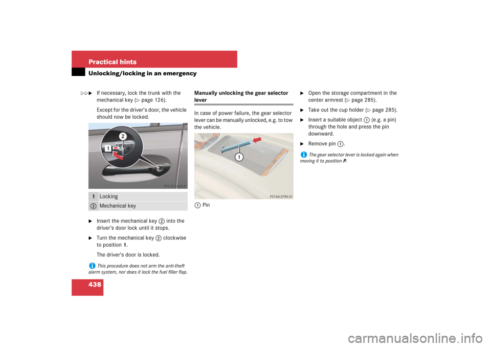
438 Practical hintsUnlocking/locking in an emergency�
If necessary, lock the trunk with the
mechanical key (
�page 126).
Except for the driver’s door, the vehicle
should now be locked.
�
Insert the mechanical key2 into the
driver’s door lock until it stops.
�
Turn the mechanical key2 clockwise
to position1.
The driver’s door is locked.Manually unlocking the gear selector
lever
In case of power failure, the gear selector
lever can be manually unlocked, e.g. to tow
the vehicle.
1Pin
�
Open the storage compartment in the
center armrest (
�page 285).
�
Take out the cup holder (
�page 285).
�
Insert a suitable object1 (e.g. a pin)
through the hole and press the pin
downward.
�
Remove pin1.
1
Locking
2
Mechanical key
i
This procedure does not arm the anti-theft
alarm system, nor does it lock the fuel filler flap.
i
The gear selector lever is locked again when
moving it to positionP.
��
Page 440 of 522
439 Practical hints
Opening/closing in an emergency
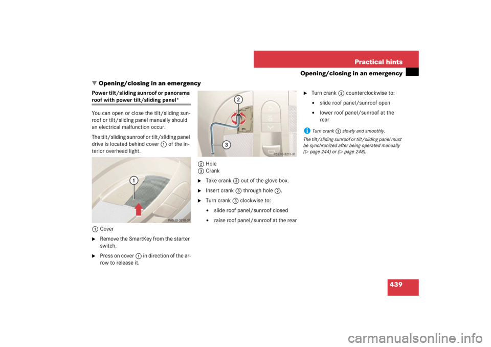
�Opening/closing in an emergency
Power tilt/sliding sunroof or panorama roof with power tilt/sliding panel*
You can open or close the tilt/sliding sun-
roof or tilt/sliding panel manually should
an electrical malfunction occur.
The tilt/sliding sunroof or tilt/sliding panel
drive is located behind cover1 of the in-
terior overhead light.
1Cover�
Remove the SmartKey from the starter
switch.
�
Press on cover1 in direction of the ar-
row to release it.2Hole
3Crank
�
Take crank3 out of the glove box.
�
Insert crank3 through hole2.
�
Turn crank3 clockwise to:�
slide roof panel/sunroof closed
�
raise roof panel/sunroof at the rear
�
Turn crank3 counterclockwise to:�
slide roof panel/sunroof open
�
lower roof panel/sunroof at the
rear
i
Turn crank3 slowly and smoothly.
The tilt/sliding sunroof or tilt/sliding panel must
be synchronized after being operated manually
(
�page 244) or (
�page 248).
Page 448 of 522
�
Turn housing cover1 counterclock-
wise and remove it.
�
Turn bulb socket4 with the bulb
counterclockwise and remove it.
�")
447 Practical hints
Replacing bulbs
Low beam bulb (halogen headlamps
only)�
Turn housing cover1 counterclock-
wise and remove it.
�
Turn bulb socket4 with the bulb
counterclockwise and remove it.
�
Pull the bulb out of bulb socket 4.
�
Press the new bulb gently into bulb
socket 4.
�
Place bulb socket4 back into the
lamp and turn it clockwise until it en-
gages.
�
Align housing cover1 and turn it
clockwise until it engages.High beam bulb/high beam flasher
bulb (halogen headlamps)/high beam
flasher bulb (Bi-Xenon* headlamps)
�
Turn bulb socket2 with the bulb
counterclockwise and remove it.
�
Pull the bulb out of bulb socket2.
�
Press the new bulb gently into bulb
socket2.
�
Place bulb socket2 back into the
lamp and turn it clockwise until it en-
gages.Front turn signal lamp bulb
�
Turn bulb socket5 with the bulb
counterclockwise and remove it.
�
Press gently onto the bulb and turn
counterclockwise out of bulb
socket5.
�
Press the new bulb gently into bulb
socket5 and turn clockwise until it
engages.
�
Place bulb socket5 back into the
lamp and turn it clockwise until it en-
gages.
Page 449 of 522
 with
the bulb counterclockwise and remove
it.
�
Pull the bulb out of bulb socket3")
448 Practical hintsReplacing bulbsParking and standing lamp bulb
Halogen headlamps�
Turn bulb socket3 (
�page 446) with
the bulb counterclockwise and remove
it.
�
Pull the bulb out of bulb socket3
(�page 446).
�
Press the new bulb gently into bulb
socket3 (
�page 446).
�
Place bulb socket3 (
�page 446)
back into the lamp and turn clockwise
until it engages.
Bi-Xenon* headlamps
In vehicles with Bi-Xenon* headlamps, the
bulbs of the parking and standing lamps
are LEDs.Additional turn signal lamp bulbs
The additional turn signal lamps in the
exterior rear view mirrors have LEDs.
If a malfunction occurs or LEDs fail to func-
tion, the entire turn signal unit must be re-
placed. Have the turn signal unit replaced
by an authorized Mercedes-Benz Center.
Front side marker lamp bulbs
Since replacing the side marker lamp bulbs
is a technically highly demanding process,
we recommend you have the side marker
lamp bulbs replaced by an authorized
Mercedes-Benz Center.
Replacing bulbs for rear lamps
Tail lamp unit
The tail lamps are equipped with HiP bulbs.
!
Do not replace the LEDs yourself. You could
otherwise damage the LEDs or parts of the vehi-
cle. Only have the LEDs replaced by an autho-
rized Mercedes-Benz Center.
Warning!
G
The bulbs in the tail lamps cannot be re-
placed individually. The tail lamp bulbs are
under pressure and could explode during an
attempt to replace them.
If the tail lamps are malfunctioning, have
them exchanged at an authorized
Mercedes-Benz Center.
Page 459 of 522

458 Practical hintsFlat tire�
Store the electrical plug 3 and the air
hose 4 behind the flap 1 and place
the electric air pump back in the desig-
nated storage space underneath the
trunk floor (
�page 432).
Lowering the vehicle
�
Lower vehicle by turning crank coun-
terclockwise until vehicle is resting ful-
ly on its own weight.
�
Remove the jack.
1-5 Wheel bolts
�
Tighten the five wheel bolts evenly, fol-
lowing the diagonal sequence illustrat-
ed (1 to 5), until all bolts are tight.
Observe a tightening torque of 96 lb-ft
(130 Nm).
Before storing the jack, it should be fully
collapsed, with handle folded in (storage
position).
�
Store the jack and the other vehicle
tools in the designated storage space
underneath the trunk floor
(�page 432).
Warning!
G
Have the tightening torque checked after
changing a wheel. The wheels could come
loose if they are not tightened to a torque of
96 lb-ft (130 Nm).
i
Wrap the damaged wheel in the protective
film that comes with the spare wheel and put the
wheel in the trunk.
You can also place the damaged wheel down into
the spare wheel well. In this case, you must stow
the holder from the spare wheel well in the trunk.
Vehicles with Advanced TPMS* (Canada only):
Do not activate the tire inflation pressure moni-
tor until a full size wheel/tire with functioning
sensor has been placed back into service on the
vehicle.
��
Page 464 of 522

463 Practical hints
Battery
�
Charge battery in accordance with the
instructions of the battery charger
manufacturer.
�
Reinstall the charged battery. Follow
the previously described steps in re-
verse order.
Reconnecting the battery�
Turn off all electrical consumers.
�
Connect the battery positive lead and
fasten its cover.
�
Connect the battery negative lead.
�
Install the luggage box (
�page 433).
!
The battery and the battery ventilation hose
must always be securely installed when the vehi-
cle is in operation.
!
Always connect the battery in the order de-
scribed below. Otherwise the vehicle’s electron-
ics can be damaged.
!
Never invert the terminal connections!
i
The following procedures must be carried
out following any interruption of battery power
(e.g. due to reconnection):
�
Set the clock (
�page 171) (see COMAND
operator’s manual).
�
Synchronize the side windows
(�page 239).
�
Synchronize the tilt/sliding sunroof
(�page 244) or the tilt/sliding panel*
(�page 248).