Page 232 of 481

Airmatic automatically selects the opti-
mum suspension tuning and ride height for
your vehicle. The Airmatic consists of two
compon")
231 Controls in detail
Driving systems
Airmatic DC (Dual Control)
Airmatic automatically selects the opti-
mum suspension tuning and ride height for
your vehicle. The Airmatic consists of two
components:�
Adaptive Damping System (ADS)
�
Vehicle level control
The ADS automatically selects the opti-
mum damping for the respective driving
conditions. At the same time the suspen-
sion is set to either Sport 1, Sport 2 or
Comfort.
Suspension tuning
The suspension tuning is set according to:
�
Your driving style
�
Road surface conditions
�
Your choice of suspension style,
Sport 1, Sport 2 or Comfort, which you
select using the damping buttonThe following suspension styles are avail-
able:
�
Comfort
Both indicator lamps2 are off.
�
Sport 1
One indicator lamp2 is on.
�
Sport 2
Both indicator lamps2 are on.
1Damping button
2Indicator lamps
�
Start the engine (
�page 51).
�
Press the damping button1 until the
desired suspension style is set.
!
If you have selected the Comfort suspen-
sion tuning (
�page 231), the vehicle lowers
slightly when you lock it within approximately
60 seconds after switching off the engine. When
parking, make sure that your vehicle cannot
come into contact with other objects, such as a
curb, while lowering. Your vehicle could
otherwise be damaged.
i
The selected suspension style is stored in
memory, even after the SmartKey is removed
from the starter switch.
Page 233 of 481

232 Controls in detailDriving systemsVehicle level control
Your vehicle automatically adjusts its ride
height to�
increase vehicle safety
�
reduce fuel consumption
The following vehicle chassis ride heights
can be selected:
�
Normal
�
Raised
The vehicle chassis ride height is raised or
lowered according to the selected level
setting and to the vehicle speed:
�
At a speed exceeding approximately
68 mph (110 km/h) with normal level
set or exceeding 75 mph (120 km/h)
with raised level set, the ride height is
reduced automatically. The table on
the next page provides an overview of
the vehicle levels.
�
With decreasing speed, the ride height
is again raised to the normal level.
Select the raised level only when required
by current driving conditions. Otherwise
�
handling may be impaired
�
fuel consumption may increase
i
These height adjustments are so small that
you may not notice any change.Warning!
G
To help avoid personal injury, keep hands
and feet away from wheel housing area, and
stay away from under the vehicle when low-
ering the vehicle chassis.
Page 234 of 481
233 Controls in detail
Driving systems
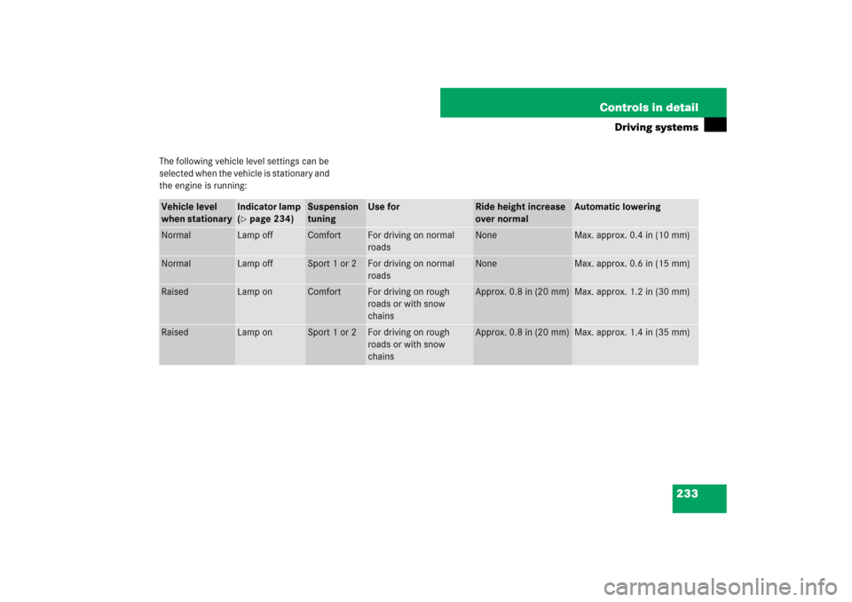
The following vehicle level settings can be
selected when the vehicle is stationary and
the engine is running:Vehicle level
when stationary
Indicator lamp
(�page 234)
Suspension
tuning
Use for
Ride height increase
over normal
Automatic lowering
Normal
Lamp off
Comfort
For driving on normal
roads
None
Max. approx. 0.4 in (10 mm)
Normal
Lamp off
Sport 1 or 2
For driving on normal
roads
None
Max. approx. 0.6 in (15 mm)
Raised
Lamp on
Comfort
For driving on rough
roads or with snow
chains
Approx. 0.8 in (20 mm)
Max. approx. 1.2 in (30 mm)
Raised
Lamp on
Sport 1 or 2
For driving on rough
roads or with snow
chains
Approx. 0.8 in (20 mm)
Max. approx. 1.4 in (35 mm)
Page 237 of 481
236 Controls in detailDriving systems
Front sensors
Rear sensorsMinimum distance
If the system detects an obstacle in this
range, all the distance warning segments
illuminate and you hear a warning signal. If
the obstacle is closer than the minimum
distance, the actual distance might no
longer be indicated by the system.Center
approx. 40 in (100 cm)
Corners
approx. 24 in (60 cm)
Center
approx. 48 in (120 cm)
Corners
approx. 32 in (80 cm)
!
During parking maneuvers, pay special at-
tention to objects located above or below the
height of the sensors (e.g. planters or trailer
hitches). The Parktronic system will not detect
such objects at close range and damage to your
vehicle or the object may result.
Ultrasonic signals from outside sources (e.g.
truck air brakes, car wash or jackhammers) may
impair the operation of the Parktronic system.
Center
approx. 8 in (20 cm)
Corners
approx. 6 in (15 cm)
Page 248 of 481

247 Controls in detail
Useful features
Cup holders Cup holder in the center console
Extending the cup holder
�
Briefly press mark on cup holder.
The cup holder automatically extends
upward.
Retracting the cup holder
�
Press mark on cup holder and push cup
holder in until it engages.
Warning!
G
In order to help prevent spilling liquids on
vehicle occupants and/or vehicle equip-
ment, only use containers that fit into the
cup holder. Use lids on open containers and
do not fill containers to a height where the
contents, especially hot liquids, could spill
during braking, vehicle maneuvers, or in an
accident. Liquids spilled on vehicle occu-
pants may cause serious personal injury.
Liquids spilled on vehicle equipment may
cause damage not covered by the
Mercedes-Benz Limited Warranty.
The cup holder must be extended when in
use with bottles.
When not in use, keep the cup holder
closed. An open cup holder may cause injury
to you or others when contacted during
braking, vehicle maneuvers, or in an acci-
dent.
Keep in mind that objects placed in the cup
holder may come loose during braking, vehi-
cle maneuvers, or in an accident and be
thrown around in the vehicle interior.
Objects thrown around in the vehicle interi-
or may cause an accident and/or serious
personal injury.
Page 288 of 481

287 Operation
Engine compartment
�
Pull release lever1.
The hood is unlocked.
1Lever for opening the hood
�
Push lever1 on the hood upwards.
�
Pull up on the hood and then release it.
The hood will be automatically held
open at shoulder height by gas-filled
struts.Closing
�
Let the hood drop from a height of
approximately 1 ft (30 cm).
The hood will lock audibly.
�
Check to make sure the hood is fully
closed.
If you can raise the hood at a point
above the headlamps, then it is not
properly closed. Open it again and let it
drop with somewhat greater force.
Engine oil
The amount of oil your engine needs will
depend on a number of factors, including
driving style. Higher oil consumption can
occur when�
the vehicle is new
�
the vehicle is driven frequently at
higher engine speeds
Engine oil consumption checks should only
be made after the vehicle break-in period.
!
To avoid damage to the windshield wipers or
hood, never open the hood if the wiper arms are
folded forward away from the windshield.
Warning!
G
When closing the hood, use extreme caution
not to catch hands or fingers. Be careful that
you do not close the hood on anyone.
Make sure that the hood is securely en-
gaged before driving off. Do not continue
driving if the hood can no longer engage af-
ter an accident, for example. The hood could
otherwise come loose while the vehicle is in
motion and endanger you and/or others.
i
Do not use any special lubricant additives,
as these may damage the drive assemblies. Us-
ing special additives not approved by
Mercedes-Benz may cause damage not covered
by the Mercedes-Benz Limited Warranty. More
information on this subject is available at any
Mercedes-Benz Center.
Page 315 of 481

314 OperationTires and wheelsTire size designation, load and speed
rating
1Tire width
2Aspect ratio in %
3Radial tire code
4Rim diameter
5Tire load rating
6Tire speed ratingGeneral:
Depending on the design standards used,
the tire size molded into the sidewall may
have no letter or a letter preceding the tire
size designation.
No letter preceding the size designation
(as illustrated above): Passenger car tire
based on European design standards.
Letter “P” preceding the size designation:
Passenger car tire based on U.S. design
standards.
Letter “LT” preceding the size designation:
Light Truck tire based on U.S. design
standards.
Letter “T” preceding the size designation:
Temporary spare tires which are high
pressure compact spares designed for
temporary emergency use only.Tire width
The tire width1 (
�page 314) indicates
the nominal tire width in mm.
Aspect ratio
The aspect ratio2 (�page 314) is the
dimensional relationship between tire
section height and section width and is
expressed in percentage. The aspect ratio
is arrived at by dividing section height by
section width.
i
For illustration purposes only. Actual data
on tires are specific to each vehicle and may vary
from data shown in above illustration.
Page 324 of 481
 of
automatic transmission, power steering,")
323 Operation
Tires and wheels
Tire and loading terminology
Accessory weight
The combined weight (in excess of those
standard items which may be replaced) of
automatic transmission, power steering,
power brakes, power windows, power
seats, radio, and heater, to the extent that
these items are available as
factory-installed equipment (whether
installed or not).
Air pressure
The amount of air inside the tire pressing
outward on each square inch of the tire.
Air pressure is expressed in pounds per
square inch (psi), or kilopascal (kPa) or
bars.
Aspect ratio
Dimensional relationship between tire
section height and section width
expressed in percentage.Bar
Another metric unit for air pressure. There
are 14.5038 pounds per square inch (psi)
to 1 bar; there are 100 kilopascals (kPa)
to 1 bar.
Bead
The tire bead contains steel wires wrapped
by steel cords that hold the tire onto the
rim.
Cold tire inflation pressure
Tire inflation pressure when your vehicle
has been sitting for at least 3 hours or driv-
en no more than 1 mile (1.6 km).
Curb weight
The weight of a motor vehicle with stan-
dard equipment including the maximum
capacity of fuel, oil, and coolant, and, if so
equipped, air conditioning and additional
optional equipment, but without passen-
gers and cargo.DOT (D
epartment o
f T
ransportation)
A tire branding symbol which denotes the
tire meets requirements of the
U.S. Department of Transportation.
GAWR (G
ross A
xle W
eight R
ating)
The GAWR is the maximum permissible
axle weight. The gross vehicle weight on
each axle must never exceed the GAWR for
the front and rear axle indicated on the
Certification label located on the driver’s
door B-pillar.
GVW (G
ross V
ehicle W
eight)
The GVW comprises the weight of the
vehicle including fuel, tools, spare wheel,
installed accessories, passengers and
cargo and, if applicable, trailer tongue
load. The GVW must never exceed the
GVWR indicated on the Certification label
located on the driver’s door B-pillar.