Page 431 of 505

430 Practical hints
Replacing bulbs
Replacing bulbs for front lamps
Before you start to replace a bulb for a
front lamp, do the following first:
�Turn the exterior lamp switch to
positionM (
�page 126).
�Open the hood (�page 315).
Front lamps halogen-type
1Housing cover for low beam headlamp
2Housing cover for high beam head-
lamp, parking and standing lamp3Bulb socket for turn signal lamp bulb
4Bulb holder of low beam bulb
5Bulb holder of high beam bulb
6Bulb socket for parking and standing
lamp bulb
Low beam bulb
�Turn housing cover1 counterclock-
wise and remove it.
�Turn bulb holder4 with the bulb coun-
terclockwise and remove it.
�Pull the bulb at its socket out of bulb
holder4.
�Insert the new bulb so that its socket
locates in the recess of bulb holder4
and is level to it.
�Reinsert bulb holder4 with the bulb in
the lamp and turn clockwise.
�Align housing cover1 and turn it
clockwise.
High beam bulb
�Turn housing cover2 counterclock-
wise and remove it.
�Turn bulb holder5 with the bulb coun-
terclockwise and remove it.
�Pull the bulb at its socket out of bulb
holder5.
�Insert the new bulb so that its socket
locates in the recess of bulb holder5
and is level to it.
�Reinsert bulb holder5 with the bulb in
the lamp and turn clockwise.
�Align housing cover2 and turn it
clockwise.
Page 432 of 505

431 Practical hints
Replacing bulbs
Front turn signal lamp bulb
�Turn bulb socket3 counterclockwise
and remove it.
�Press gently onto the bulb and turn
counterclockwise out of bulb
socket3.
�Press the new bulb gently into bulb
socket3 and turn clockwise until it
engages.
�Place bulb socket3 back into the
lamp and turn it clockwise.
Parking and standing lamp bulb
�Turn housing cover2 counterclock-
wise and remove it.
�Pull out bulb socket6 with the bulb.
�Pull the bulb out of the bulb socket6.
�Press the new bulb into bulb socket6.
�Press bulb socket6 back into the
lamp.
�Align housing cover2 and turn it
clockwise.Front lamps Bi-Xenon*-type
1Bulb socket for turn signal lamp
2Housing cover for high beam flasher,
parking and standing lamp
3Housing cover for Bi-Xenon* headlamp4Bulb holder for high beam flasher bulb
5Bulb socket for parking and standing
lamp bulb
High beam bulb for high beam flasher
�Turn housing cover2 counterclock-
wise and remove it.
�Turn bulb holder4 with the bulb coun-
terclockwise and remove it.
�Pull the bulb at its socket out of bulb
holder4.
�Insert the new bulb so that its socket
locates in the recess of bulb holder4
and is level to it.
Warning!G
Do not remove the cover 3 for the Bi-Xe-
non* headlamp. Because of high voltage in
Xenon lamps, it is dangerous to replace the
bulb or repair the lamp and its components.
We recommend that you have such work
done by a qualified technician.
��
Page 433 of 505

432 Practical hints
Replacing bulbs
�Reinsert bulb holder4 with the bulb in
the lamp and turn clockwise.
�Align housing cover2 and turn it
clockwise.
Front turn signal lamp bulb
�Turn bulb socket1 counterclockwise
and remove it.
�Press gently onto the bulb and turn
counterclockwise out of bulb
socket1.
�Press the new bulb gently into bulb
socket1 and turn clockwise until it
engages.
�Place bulb socket1 back into the
lamp and turn it clockwise.
Parking and standing lamp bulb
�Turn housing cover2 counterclock-
wise and remove it.
�Pull out bulb socket5 with the bulb.
�Pull the bulb out of the bulb socket5.
�Press the new bulb into bulb socket5.
�Press bulb socket5 back into the
lamp.
�Align housing cover2 and turn it
clockwise.
Additional turn signal lamps
The additional turn signal lamps in the ex-
terior rear view mirrors have LEDs.
If a malfunction occurs or LEDs fail to func-
tion, the entire turn signal unit must be re-
placed. Have the additional turn signal unit
replaced by an authorized Mercedes-Benz
Center.
Front side marker lamp
Since replacing the side marker lamp bulbs
is a technically highly demanding process,
we recommend you have the side marker
lamp bulbs replaced by an authorized
Mercedes-Benz Center.
Replacing bulbs for rear lamps
Before you start to replace a bulb for a rear
lamp, do the following first:
�Turn the exterior lamp switch to
positionM (
�page 126).
Tail lamp unit
�Open trunk lid.
�Swing the trim panel covering the cor-
responding rear lights to the side.
1Connector
2Tab
�Disconnect electrical connector1.
��
Page 434 of 505
433 Practical hints
Replacing bulbs
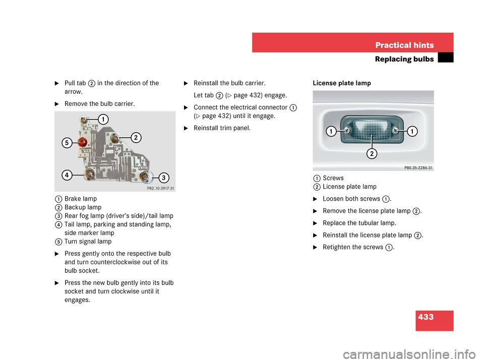
�Pull tab2 in the direction of the
arrow.
�Remove the bulb carrier.
1Brake lamp
2Backup lamp
3Rear fog lamp (driver’s side)/tail lamp
4Tail lamp, parking and standing lamp,
side marker lamp
5Turn signal lamp
�Press gently onto the respective bulb
and turn counterclockwise out of its
bulb socket.
�Press the new bulb gently into its bulb
socket and turn clockwise until it
engages.
�Reinstall the bulb carrier.
Let tab2 (
�page 432) engage.
�Connect the electrical connector1
(
�page 432) until it engage.
�Reinstall trim panel.License plate lamp
1Screws
2License plate lamp
�Loosen both screws1.
�Remove the license plate lamp2.
�Replace the tubular lamp.
�Reinstall the license plate lamp2.
�Retighten the screws1.
Page 446 of 505
445 Practical hints
Flat tire
�Unscrew the alignment bolt, install last
wheel bolt and tighten slightly.Lowering the vehicle
�Lower vehicle by turning crank coun-
terclockwise until the full weight of the
vehicle is resting on the ground.
�Remove the jack.
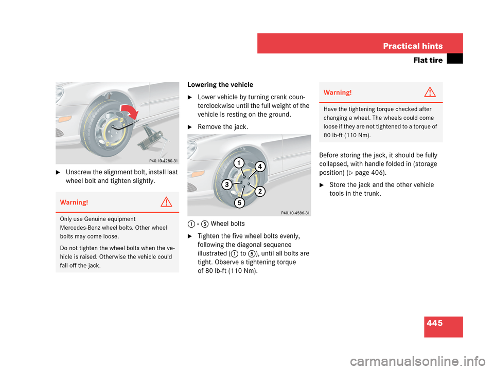
1 - 5 Wheel bolts
�Tighten the five wheel bolts evenly,
following the diagonal sequence
illustrated (1 to 5), until all bolts are
tight. Observe a tightening torque
of 80 lb-ft (110 Nm).Before storing the jack, it should be fully
collapsed, with handle folded in (storage
position) (
�page 406).
�Store the jack and the other vehicle
tools in the trunk.
Warning!G
Only use Genuine equipment
Mercedes-Benz wheel bolts. Other wheel
bolts may come loose.
Do not tighten the wheel bolts when the ve-
hicle is raised. Otherwise the vehicle could
fall off the jack.
Warning!G
Have the tightening torque checked after
changing a wheel. The wheels could come
loose if they are not tightened to a torque of
80 lb-ft (110 Nm).
Page 450 of 505

449 Practical hints
Battery
Charging and reinstalling the battery
�Charge battery in accordance with the
instructions of the battery charger
manufacturer.
�Reinstall the charged battery. Follow
the previously described steps in
reverse order.
Reconnecting the battery
�Turn off all electrical consumers.
�Remove SmartKey from starter switch.
Vehicles with KEYLESS-GO*:
�Open the driver’s door.
�Connect the battery positive lead and
fasten its cover3 (
�page 448).
�Connect the battery negative lead2
(
�page 448).
�Reinstall the filter box (�page 447).Batteries contain materials that can harm
the environment if disposed of improperly.
Large 12-volt storage batteries contain
lead. Recycling of batteries is the preferred
method of disposal. Many states require
sellers of batteries to accept old batteries
for recycling.
Warning!G
Never charge a battery while still installed in
the vehicle unless the accessory battery
charge unit approved by Mercedes-Benz is
being used. Gases may escape during charg-
ing and cause explosions that may result in
paint damage, corrosion or personal injury.
An accessory battery charge unit specially
adapted for Mercedes-Benz vehicles and
tested and approved by Mercedes-Benz is
available, permitting the charging of the bat-
tery in its installed position. Contact an au-
thorized Mercedes-Benz Center for
information and availability. Charge battery
in accordance with the separate instruc-
tions for the accessory battery charger.
!The battery, its filler caps and the ventilation
hose must always be securely installed when the
vehicle is in operation.
!Always connect the battery in the order de-
scribed below. Otherwise the vehicle’s electron-
ics can be damaged.
!Never invert the terminal connections!
iThe following procedures must be carried
out following any interruption of battery power
(e.g. due to reconnecting):
�Set the clock (�page 158). Vehicles with
COMAND*: see COMAND operator’s manu-
al.
�Synchronize the side windows
(
�page 251).
Page 458 of 505
457 Practical hints
Fuses
Mainfuse box in passenger
compartment
The main fuse box is located in the passen-
ger compartment on the driver’s side of
the cockpit.
1Main fuse box coverOpening fuse box�Open the driver’s door.
�Insert flat, blunt object as a lever into
the edge of the fuse box cover1 at
the position indicated by the arrow.
�Loosen fuse box cover1 from cockpit
using lever.
�Using your hands, remove fuse box
cover1 rearward.
Closing fuse box
�Attach fuse box cover1 in the front.
�Fold fuse box cover1 in until it
engages.
Fuse box in engine compartment
The fuse box is located in the engine com-
partment on the driver’s side.
1Cover
2Screw
3Retainer
Removing cover
�Twist screws2 90° counterclock-
wise.
�Lift the rear of cover1.
�Slide out retainer3 and remove
cover1 by pulling towards front.
!Do not use sharp objects such as a screw
driver to open the fuse box cover1 in the cock-
pit, as this could damage it.
Page 459 of 505
458 Practical hints
Fuses
Opening fuse box
4Fuse box cover
5Clamps
�With a dry cloth, remove any moisture
from the fuse box.
�Release clamps5.
�Remove fuse box cover4.Closing fuse box
�Make sure that the sealing rubber is
properly positioned.
�Press fuse box cover4 down and
secure with clamps5.
Installing cover
�Insert cover1 sideways into
retainer3.
�Twist screws2 90° clockwise.
Fuse box in trunk
The fuse box is located in the trunk behind
the left-hand trim panel.
1Trim panel
Opening fuse box
�To open, pull trim panel1 in the direc-
tion of the rear light and outward.
Closing fuse box
�Press trim panel1 back into place.
!The fuse box cover4 must be properly po-
sitioned as described to prevent moisture or dirt
from entering the fuse box and possibly impair-
ing fuse operation.