Page 193 of 505

192 Controls in detail
Climate control
Setting the temperature
Use temperature controls2 and3
(
�page 189) to separately adjust the air
temperature on each side of the passenger
compartment. You should raise or lower
the temperature setting in small incre-
ments, preferably starting at 72°F (22°C).
The climate control will adjust to the set
temperature as fast as possible.
Increasing
�Turn temperature control2
and/or3 (
�page 189) slightly clock-
wise.
The climate control system will corre-
spondingly adjust the interior air tem-
perature.Decreasing
�Turn temperature control2
and/or3 (
�page 189) slightly coun-
terclockwise.
The climate control system will corre-
spondingly adjust the interior air tem-
perature.
Adjusting air distribution
Use air distribution control4
(
�page 189) to adjust the air distribution.
The following symbols are located on the
controls:
iIf you turn the temperature control fully
clockwise for one side of the vehicle, you are in-
creasing the temperature for the other side of
the vehicle as well.
iIf you turn the temperature control fully
counterclockwise for one side of the vehicle, you
are decreasing the temperature for the other
side of the vehicle as well.
SymbolFunction
aDirects air through the center,
side and rear passenger
compartment air vents
ZDirects air to the windshield
and the side defroster vents
bDirects air into the entire
vehicle interior
YDirects air to the footwells
Page 314 of 505

313 Operation
At the gas station
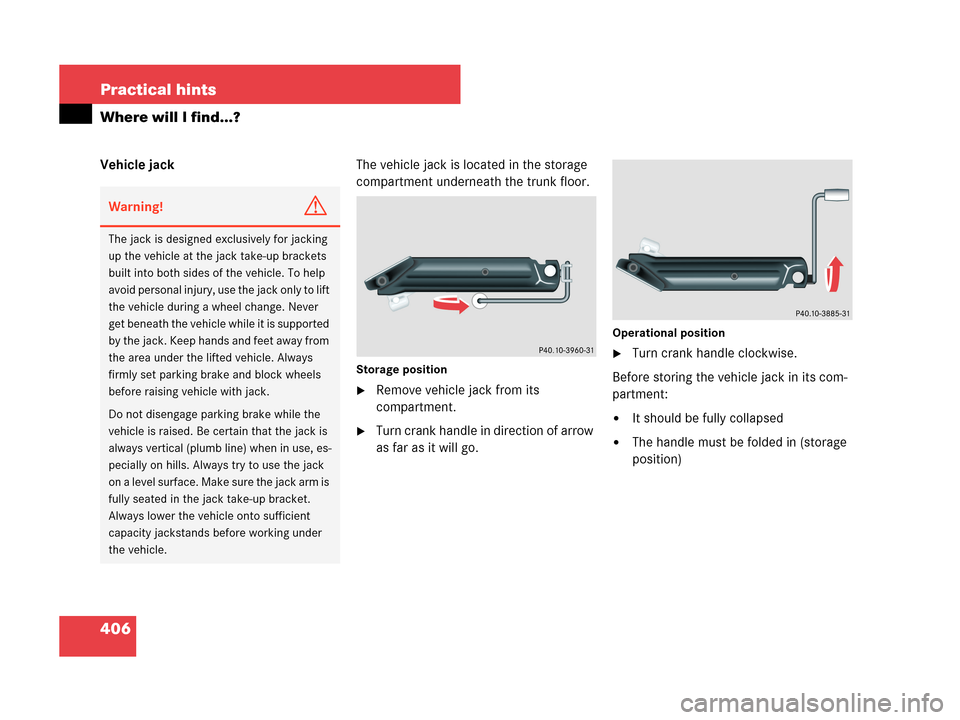
�Take off cap and set it in direction of
arrow2 in the recess on the fuel filler
flap.
To prevent fuel vapors from escaping
into open air, fully insert filler nozzle
unit.
�Only fill your tank until the filler nozzle
unit cuts out – do not top up or
overfill.
�Replace fuel cap by turning it clockwise
until it audibly engages.
�Close fuel filler flap.
Warning!G
Overfilling of the fuel tank may create
pressure in the system which could cause a
gas discharge. This could cause the gas to
spray back out when removing the fuel
pump nozzle, which could cause personal
injury.
iMake sure to close the fuel filler flap before
locking your vehicle as the flap locking pin
prevents closing after you have locked the
vehicle.
iOnly use premium unleaded gasoline with a
minimum Posted Octane Rating of 91 (average
of 96 RON / 86 MON).
Information on gasoline quality can normally be
found on the fuel pump.
For more information on gasoline, see “Premium
unleaded gasoline” (
�page 475) or the Factory
Approved Service Products pamphlet.
iLeaving the engine running and the fuel cap
open can cause theú malfunction indicator
lamp (USA only) or the± malfunction indica-
tor lamp (Canada only) to illuminate.
More information can be found in the “Practical
hints” section (
�page 369).
Page 407 of 505

406 Practical hints
Where will I find...?
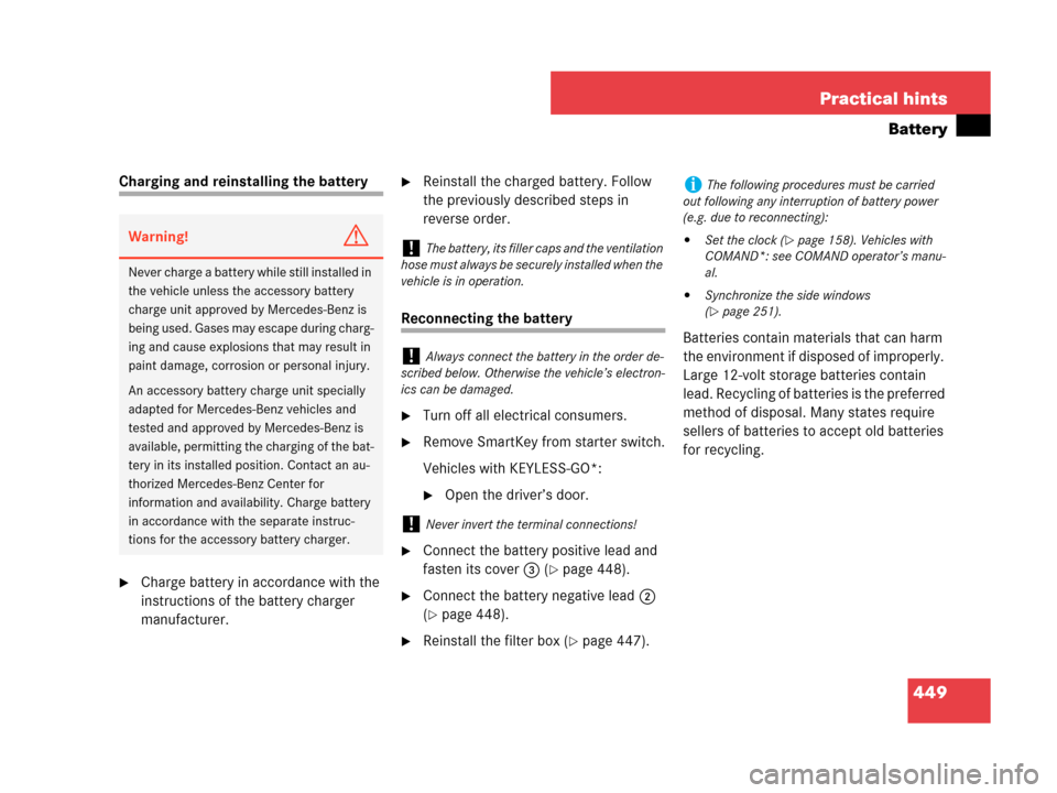
Vehicle jackThe vehicle jack is located in the storage
compartment underneath the trunk floor.
Storage position
�Remove vehicle jack from its
compartment.
�Turn crank handle in direction of arrow
as far as it will go.
Operational position
�Turn crank handle clockwise.
Before storing the vehicle jack in its com-
partment:
�It should be fully collapsed
�The handle must be folded in (storage
position)
Warning!G
The jack is designed exclusively for jacking
up the vehicle at the jack take-up brackets
built into both sides of the vehicle. To help
avoid personal injury, use the jack only to lift
the vehicle during a wheel change. Never
get beneath the vehicle while it is supported
by the jack. Keep hands and feet away from
the area under the lifted vehicle. Always
firmly set parking brake and block wheels
before raising vehicle with jack.
Do not disengage parking brake while the
vehicle is raised. Be certain that the jack is
always vertical (plumb line) when in use, es-
pecially on hills. Always try to use the jack
on a level surface. Make sure the jack arm is
fully seated in the jack take-up bracket.
Always lower the vehicle onto sufficient
capacity jackstands before working under
the vehicle.
Page 408 of 505
407 Practical hints
Where will I find...?
Setting up the collapsible wheel chock
The collapsible wheel chock serves to
additionally secure the vehicle, e.g. while
changing the wheel.
1Tilt the plate upward
2Fold the lower plate outward
3Insert the plate�Tilt both plates upward1.
�Fold the lower plate outward2.
�Guide the tabs of the lower plate all the
way into the openings of the base
plate3.
For information on where to place wheel
chocks when changing a wheel, see “Lift-
ing the vehicle” (
�page 441).
Minispare wheel
The Minispare wheel is located in the
storage compartment underneath the
trunk floor.
Removing the Minispare wheel
�Lift up trunk floor cover and engage
trunk floor handle in upper edge of
trunk.
�Loosen the retaining screw in the mid-
dle of storage well casing by turning it
counterclockwise (
�page 405).
�Remove the storage well casing
(
�page 405).��
Page 450 of 505

449 Practical hints
Battery
Charging and reinstalling the battery
�Charge battery in accordance with the
instructions of the battery charger
manufacturer.
�Reinstall the charged battery. Follow
the previously described steps in
reverse order.
Reconnecting the battery
�Turn off all electrical consumers.
�Remove SmartKey from starter switch.
Vehicles with KEYLESS-GO*:
�Open the driver’s door.
�Connect the battery positive lead and
fasten its cover3 (
�page 448).
�Connect the battery negative lead2
(
�page 448).
�Reinstall the filter box (�page 447).Batteries contain materials that can harm
the environment if disposed of improperly.
Large 12-volt storage batteries contain
lead. Recycling of batteries is the preferred
method of disposal. Many states require
sellers of batteries to accept old batteries
for recycling.
Warning!G
Never charge a battery while still installed in
the vehicle unless the accessory battery
charge unit approved by Mercedes-Benz is
being used. Gases may escape during charg-
ing and cause explosions that may result in
paint damage, corrosion or personal injury.
An accessory battery charge unit specially
adapted for Mercedes-Benz vehicles and
tested and approved by Mercedes-Benz is
available, permitting the charging of the bat-
tery in its installed position. Contact an au-
thorized Mercedes-Benz Center for
information and availability. Charge battery
in accordance with the separate instruc-
tions for the accessory battery charger.
!The battery, its filler caps and the ventilation
hose must always be securely installed when the
vehicle is in operation.
!Always connect the battery in the order de-
scribed below. Otherwise the vehicle’s electron-
ics can be damaged.
!Never invert the terminal connections!
iThe following procedures must be carried
out following any interruption of battery power
(e.g. due to reconnecting):
�Set the clock (�page 158). Vehicles with
COMAND*: see COMAND operator’s manu-
al.
�Synchronize the side windows
(
�page 251).
Page 484 of 505

483 Index
C
California retail buyers and lessees,
Important notice for 11
Call priority (Tele Aid) 292
Can holder see Cup holder
Capacities and
recommended fuels/lubricants 472
Cargo area see Trunk
Carpets, cleaning 363
Catalytic converter 310
CD changer* 227
MP3 228
CD player 227
Control system 150
Center console 29
Lower part 30
Upper part 29
Central locking
Automatic 117, 164
Locking/unlocking from inside 118
Central locking switch 118
Certification label 462
Certification label, examples 462
Charcoal filter 207Children in the vehicle 82
Air bags 82
Blocking rear
side window operation 86
Front passenger front
air bag off indicator lamp 74
Infant and
child restraint systems 75, 82
LATCH-type child seat anchors 85
Occupant Classification System
(OCS) 71
Cigarette lighter 282
Climate control see
Climate control system
Climate control system
Air conditioning refrigerant 474
Air conditioning, Cooling 196, 208
Air distribution 192, 203
Air recirculation mode 194, 205
Air vents 197, 210
Air volume 192, 193, 204
Charcoal filter 207
Control panel,
Automatic climate control 199Control panel, Climate control 189
Deactivating/Reactivating 191, 201
Defogging 204
Defrosting 204
Defrosting, Rear window 187
Front defroster 193
MAXCOOL 205
Residual engine heat
and ventilation* (REST*) 209
Temperature 192, 202
Clock 27, 138, 158
Setting time 158
Cockpit 24
Cold tire inflation pressure 347
Collapsible wheel chock 404, 407
COMAND* see separate
COMAND operating instructions
Combination switch 54, 130
Control system 139
Functions 143
Multifunction display 139
Multifunction steering wheel 140
Resetting to factory default 153