Page 159 of 723

158 Control systems
COMAND navigation (introduction)
1Crosshair
2Details of the crosshair position
3Map scaleAdjusting the map scale
�Rotate ymz.
Rotating clockwise zooms in, rotating
counterclockwise zooms out.
Saving crosshair position as destination
in last destinations list
�Showing menu system, if neces-
sary: Press n.
�Saving: Select “Position” � “Save Po-
sition”.
COMAND saves the crosshair position
as a destination in the last destinations
list (
�page 213).
Hiding the crosshair
�Press back button L in the center
console (
�page 82).
The crosshair disappears and the map
is centered on the vehicle position.
or
�Set the map to the vehicle or destina-
tion position, see the explanation be-
low.
Centering the map on the vehicle or
destination position
�Centering on the vehicle’s position:
Select “Navi” � “Position” � “Vehicle
Position Map”.
or
�Press back button L when the
crosshair is displayed.
�Centering on the destination:
Select “Navi” � “Position” � “Destina-
tion Position Map”.
iDisplay 2 may be the name of a road, for
example, provided the digital map contains the
necessary data.
If no data is available, display 2 shows:
�the coordinates of the crosshair if the
geo-coordinate display is switched on
(
�page 160) and the GPS signal is strong
enough
�no display if the geo-coordinate display is
switched off (
�page 160)
iIf you have moved the map, you can use this
function to rapidly return the map to the position
of the vehicle or destination. It is only possible to
center the map on the destination position when
route guidance is active.
Page 186 of 723
185 Control systems
COMAND navigation system (entering a destination)
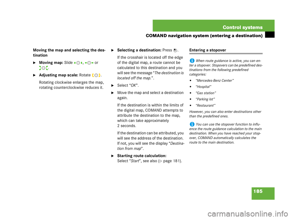
Moving the map and selecting the des-
tination
�Moving map: Slide qmr, omp or
wmx.
�Adjusting map scale: Rotate ymz.
Rotating clockwise enlarges the map,
rotating counterclockwise reduces it.
�Selecting a destination: Press n.
If the crosshair is located off the edge
of the digital map, a route cannot be
calculated to this destination and you
will see the message “The destination is
located off the map.”.
�Select “OK”.
�Move the map and select a destination
again.
If the destination is within the limits of
the digital map, COMAND attempts to
attribute the destination to the map,
which can take approximately
2 seconds.
If the destination can be attributed, you
will see the address of the destination.
If not, you will see the display “Destina-
tion from map”.
�Starting route calculation:
Select “Start”, see also (
�page 181).
Entering a stopover
iWhen route guidance is active, you can en-
ter a stopover. Stopovers can be predefined des-
tinations from the following predefined
categories:
�“Mercedes-Benz Center”
�“Hospital”
�“Gas station”
�“Parking lot”
�“Restaurant”
However, you can also enter destinations other
than the predefined ones.
iYou can use the stopover function to influ-
ence the route guidance calculation to the main
destination. When you have reached your stop-
over, COMAND automatically calculates the
route to the main destination.
Page 205 of 723

204 Control systems
COMAND navigation system (during route guidance)
Displaying route information
�Select “Route” � “Route Info” in map
view with the menu system displayed
(
�page 157).
The route information appears.
Example display with main destination and
stopover
1Distance to the destination
2Symbol = for stopover
3Abbreviation for province (CDN) or
state (USA)
4Town/city
5Street
6Symbol < for main destination
7Estimated driving time to the destina-
tion
8Estimated arrival time
�Closing route info: Slide omp or
press back button L in the center
console (
�page 82).
iCOMAND uses the time set in COMAND as
the basis for calculating the estimated arrival
time. The clock must be set correctly in
COMAND (
�page 227). The calculation of the
estimated arrival time does not additionally take
into account whether Daylight Saving Time or
standard time is applicable at the destination. If
the destination is in a different time zone, arrival
time display
8 is in local time. This is indicated
by “LT” in the display.
The following data cannot be seen until the route
calculation has been completed:
�Distance to destination 1
�Estimated arrival time 8
�Estimated remaining travel time 7
If the destination is located within a partially dig-
itized area, the following data may differ from the
facts:
�Distance to destination 1
�Estimated arrival time 8
�Estimated remaining travel time 7
Page 206 of 723
205 Control systems
COMAND navigation system (during route guidance)
Detour function
�Select “Route” � “Detour” in map view
with the menu system displayed
(
�page 157).
The detour function display appears.
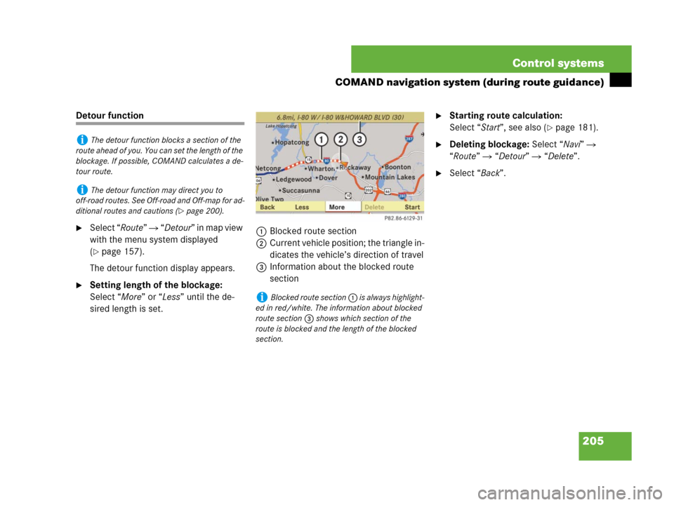
�Setting length of the blockage:
Select “More” or “Less” until the de-
sired length is set.1Blocked route section
2Current vehicle position; the triangle in-
dicates the vehicle’s direction of travel
3Information about the blocked route
section
�Starting route calculation:
Select “Start”, see also (
�page 181).
�Deleting blockage: Select “Navi” �
“Route” � “Detour” � “Delete”.
�Select “Back”.
iThe detour function blocks a section of the
route ahead of you. You can set the length of the
blockage. If possible, COMAND calculates a de-
tour route.
iThe detour function may direct you to
off-road routes. See Off-road and Off-map for ad-
ditional routes and cautions (
�page 200).
iBlocked route section 1 is always highlight-
ed in red/white. The information about blocked
route section 3 shows which section of the
route is blocked and the length of the blocked
section.
Page 234 of 723
233 Control systems
COMAND system settings
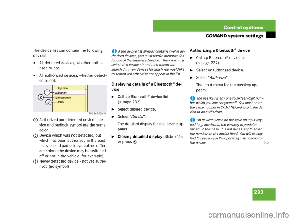
The device list can contain the following
devices:
�All detected devices, whether autho-
rized or not.
�All authorized devices, whether detect-
ed or not.
1Authorized and detected device – de-
vice and padlock symbol are the same
color
2Device which was not detected, but
which has been authorized in the past
– device and padlock symbol are differ-
ent colors (the device may be switched
off or not in the vehicle, for example)
3Newly detected device - not yet autho-
rized (no symbol)Displaying details of a Bluetooth
® de-
vice
�Call up Bluetooth® device list
(
�page 232).
�Select desired device.
�Select “Details”.
The detailed display for this device ap-
pears.
�Closing detailed display: Slide qmr
or press n.Authorizing a Bluetooth
® device
�Call up Bluetooth® device list
(
�page 232).
�Select unauthorized device.
�Select “Authorize”.
The input menu for the passkey ap-
pears.
iIf the device list already contains twelve au-
thorized devices, you must revoke authorization
for one of the authorized devices. Then you must
switch this device off and then restart the
search. Any new devices for which you would like
to search will otherwise not appear in the list.
iThe passkey is any one to sixteen-digit num-
ber which you can set yourself. You must enter
t he s ame n umb er in C OM AND an d als o in th e de-
vice to be authorized.
iOn devices which do not have an input key-
pad (e.g. headsets), the passkey is predeter-
mined. In this case, it is not necessary to enter
the number on the device itself. You will usually
find the passkey in the operating instructions for
the device.
��
Page 236 of 723
235 Control systems
COMAND vehicle menu
�COMAND vehicle menu
In this menu, you can program the follow-
ing vehicle functions:Setting night security illumination
(Exterior Lighting Delayed Switch-off)
Use this function to set whether and how
long you would like the exterior lighting to
illuminate during darkness after exiting the
vehicle and both doors closed.
The exterior lighting automatically goes
out after the delayed switch-off time has
expired.
You can select:
�“0 sec.”, the delayed switch-off feature
is deactivated
�“15 sec.”, “30 sec.”, “45 sec.”, or
“60 sec.”, the delayed switch-off fea-
ture is activated
�Select “Vehicle”.
The main area is active.
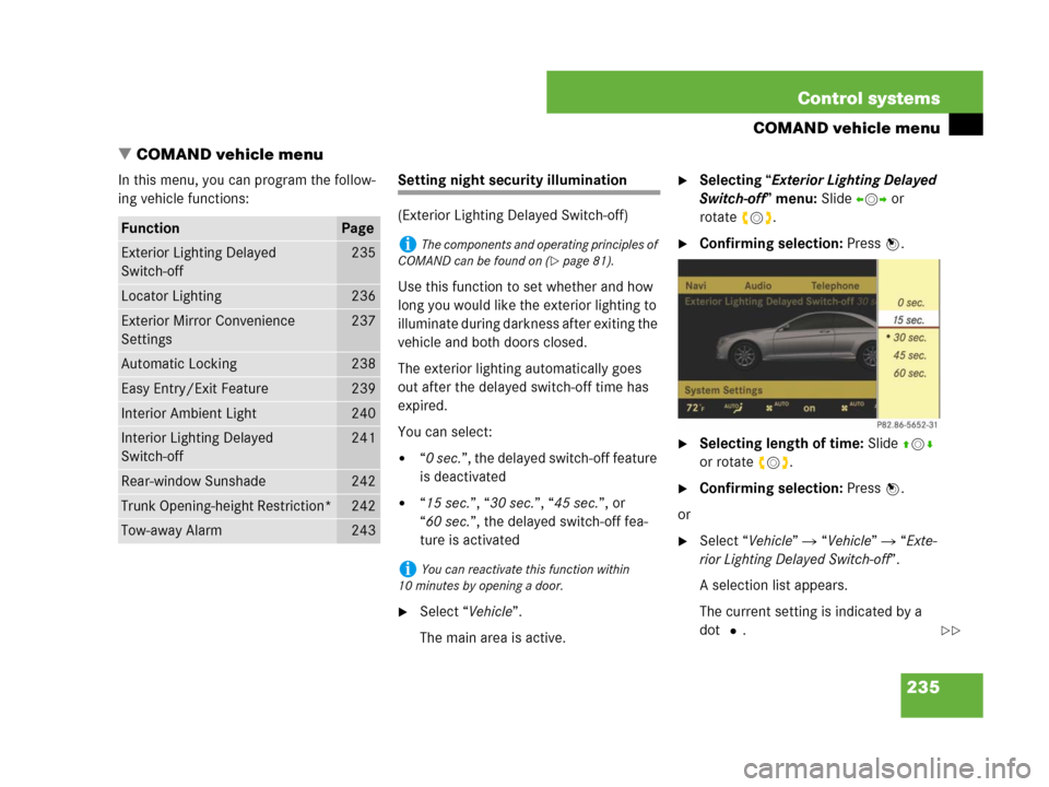
�Selecting “Exterior Lighting Delayed
Switch-off” menu: Slide omp or
rotateymz.
�Confirming selection: Press n.
�Selecting length of time: Slide qmr
or rotate ymz.
�Confirming selection: Press n.
or
�Select “Vehicle” � “Vehicle” � “Exte-
rior Lighting Delayed Switch-off”.
A selection list appears.
The current setting is indicated by a
dotR.
FunctionPage
Exterior Lighting Delayed
Switch-off235
Locator Lighting236
Exterior Mirror Convenience
Settings237
Automatic Locking238
Easy Entry/Exit Feature239
Interior Ambient Light240
Interior Lighting Delayed
Switch-off241
Rear-window Sunshade242
Trunk Opening-height Restriction*242
Tow-away Alarm243
iThe components and operating principles of
COMAND can be found on (
�page 81).
iYou can reactivate this function within
10 minutes by opening a door.
��
Page 237 of 723
236 Control systems
COMAND vehicle menu
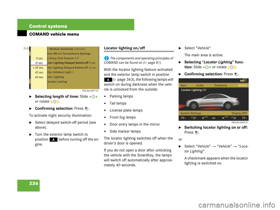
�Selecting length of time: Slide qmr
or rotate ymz.
�Confirming selection: Press n.
To activate night security illumination:
�Select delayed switch-off period (see
above).
�Turn the exterior lamp switch to
position* before turning off the en-
gine.
Locator lighting on/off
With the locator lighting feature activated
and the exterior lamp switch in position
*(
�page 363), the following lamps will
switch on during darkness when the vehi-
cle is unlocked from the outside:
�Parking lamps
�Tail lamps
�License plate lamps
�Front fog lamps
�Door entry lamps in the mirror
�Side marker lamps
The locator lighting switches off when the
driver’s door is opened.
If you do not open a door after unlocking
the vehicle with the SmartKey, the lamps
will switch off automatically after approxi-
mately 40 seconds.
�Select “Vehicle”.
The main area is active.
�Selecting “Locator Lighting” func-
tion: Slide omp or rotate ymz.
�Confirming selection: Press n.
�Switching locator lighting on or off:
Press n.
or
�Select “Vehicle” � “Vehicle” � “Loca-
tor Lighting”.
A checkmark appears when the locator
lighting is switched on.
iThe components and operating principles of
COMAND can be found on (
�page 81).
��
Page 238 of 723
237 Control systems
COMAND vehicle menu
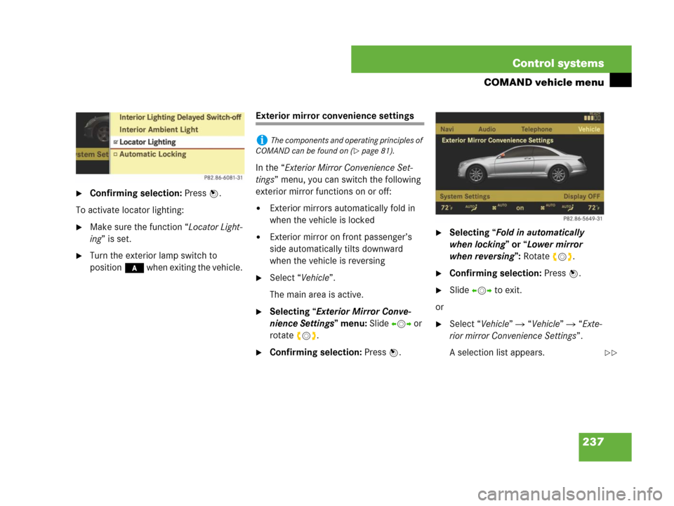
�Confirming selection: Press n.
To activate locator lighting:
�Make sure the function “Locator Light-
ing” is set.
�Turn the exterior lamp switch to
position* when exiting the vehicle.
Exterior mirror convenience settings
In the “Exterior Mirror Convenience Set-
tings” menu, you can switch the following
exterior mirror functions on or off:
�Exterior mirrors automatically fold in
when the vehicle is locked
�Exterior mirror on front passenger’s
side automatically tilts downward
when the vehicle is reversing
�Select “Vehicle”.
The main area is active.
�Selecting “Exterior Mirror Conve-
nience Settings” menu: Slide omp or
rotate ymz.
�Confirming selection: Press n.
�Selecting “Fold in automatically
when locking” or “Lower mirror
when reversing”: Rotateymz.
�Confirming selection: Press n.
�Slide omp to exit.
or
�Select “Vehicle” � “Vehicle” � “Exte-
rior mirror Convenience Settings”.
A selection list appears.
iThe components and operating principles of
COMAND can be found on (
�page 81).
��