Page 180 of 467
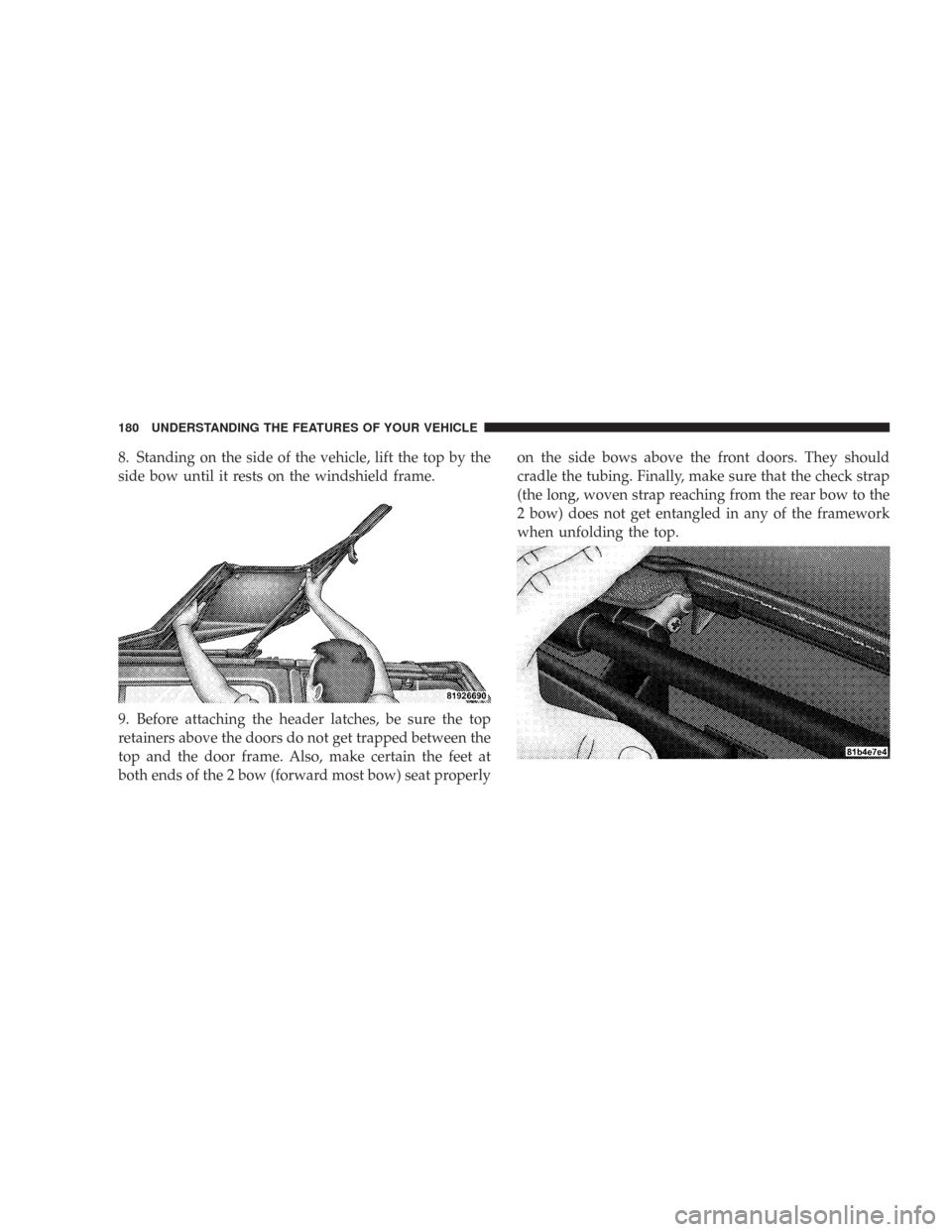
8. Standing on the side of the vehicle, lift the top by the
side bow until it rests on the windshield frame.
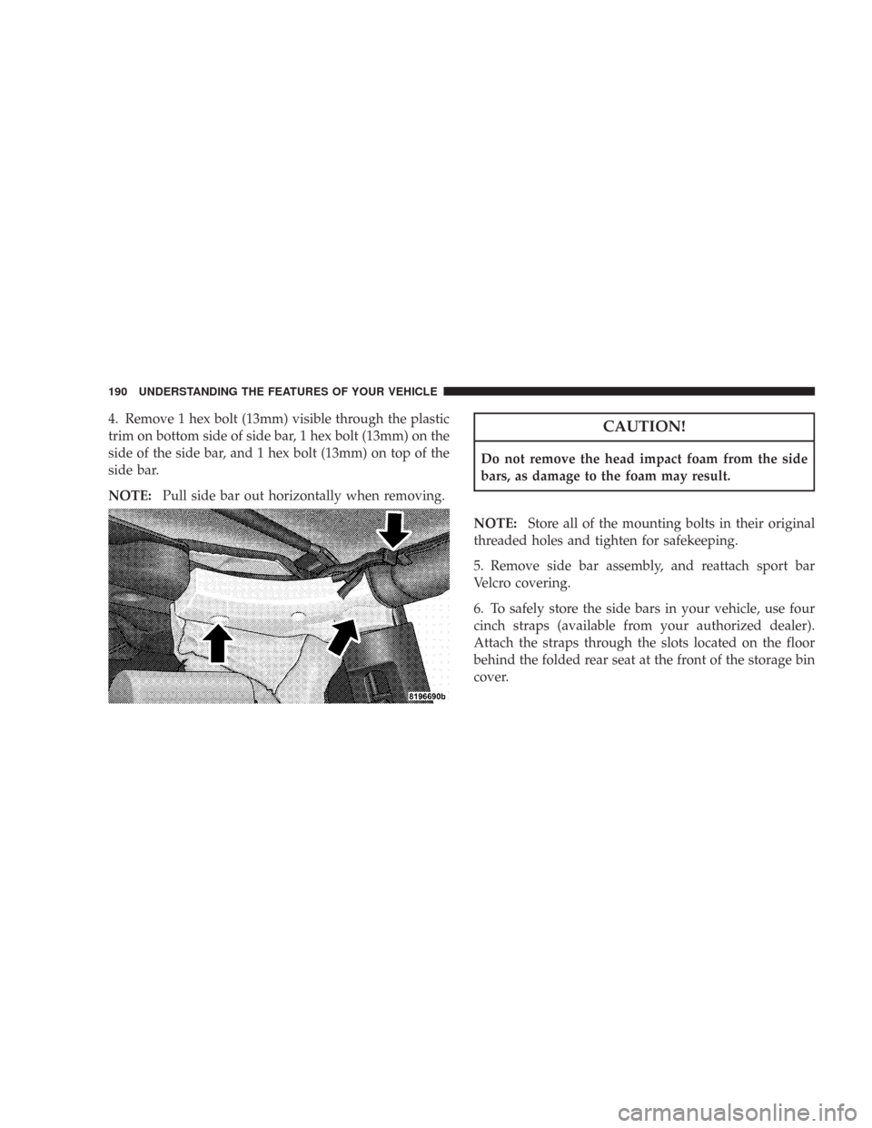
9. Before attaching the header latches, be sure the top
retainers above the doors do not get trapped between the
top and the door frame. Also, make certain the feet at
both ends of the 2 bow (forward most bow) seat properlyon the side bows above the front doors. They should
cradle the tubing. Finally, make sure that the check strap
(the long, woven strap reaching from the rear bow to the
2 bow) does not get entangled in any of the framework
when unfolding the top.
180 UNDERSTANDING THE FEATURES OF YOUR VEHICLE
Page 183 of 467
15. Insert the front retainer of the window into the door
channel, making sure the retainer is fully seated and
properly positioned on the door frame. Failure to do so
can result in wind and water leaks or damage to the
window.16. Continue closing the zipper only along the top edge
of the window.
UNDERSTANDING THE FEATURES OF YOUR VEHICLE 183
3
Page 188 of 467

Raise the windshield and reinstall the side bars as soon as
the task that required their removal is completed and
before you return to on-road driving. Both you and your
passenger should wear seat belts at all times, on-road and
off-road, regardless of whether the windshield is raised
or folded down.
Outside rear view mirrors are mounted on the doors. If
you choose to remove the doors, see your authorized
dealer for a replacement cowl-mounted outside mirror.
Federal law requires outside mirrors on vehicles for
on-road use.WARNING!
Carefully follow these warnings to help protect against
personal injury:
•Do not drive your vehicle on-road with the windshield
down.
•Do not drive your vehicle unless the windshield is
securely fastened, either up or down.
•Eye protection, such as goggles, should be worn at all
times when the windshield is down.
•
Be sure that you carefully follow the instructions for
raising the windshield. Make sure that the folding wind-
shield, windshield wipers, side bars, and all associated
hardware and fasteners are correctly and tightly as-
sembled before driving your vehicle. Failure to follow
these instructions may prevent your vehicle from provid-
ing you and your passengers protection in some accidents.
•If you remove the doors, store them outside the vehicle.
In the event of an accident, a loose door may cause
personal injury.
188 UNDERSTANDING THE FEATURES OF YOUR VEHICLE
Page 190 of 467
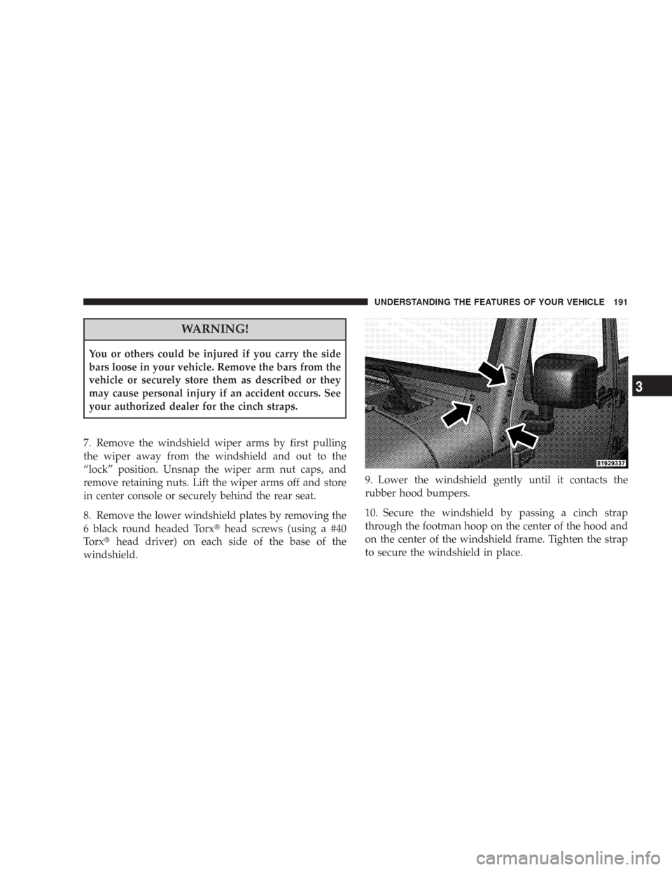
4. Remove 1 hex bolt (13mm) visible through the plastic
trim on bottom side of side bar, 1 hex bolt (13mm) on the
side of the side bar, and 1 hex bolt (13mm) on top of the
side bar.
NOTE:Pull side bar out horizontally when removing.CAUTION!
Do not remove the head impact foam from the side
bars, as damage to the foam may result.
NOTE:Store all of the mounting bolts in their original
threaded holes and tighten for safekeeping.
5. Remove side bar assembly, and reattach sport bar
Velcro covering.
6. To safely store the side bars in your vehicle, use four
cinch straps (available from your authorized dealer).
Attach the straps through the slots located on the floor
behind the folded rear seat at the front of the storage bin
cover.
190 UNDERSTANDING THE FEATURES OF YOUR VEHICLE
Page 191 of 467
WARNING!
You or others could be injured if you carry the side
bars loose in your vehicle. Remove the bars from the
vehicle or securely store them as described or they
may cause personal injury if an accident occurs. See
your authorized dealer for the cinch straps.
7. Remove the windshield wiper arms by first pulling
the wiper away from the windshield and out to the
“lock” position. Unsnap the wiper arm nut caps, and
remove retaining nuts. Lift the wiper arms off and store
in center console or securely behind the rear seat.
8. Remove the lower windshield plates by removing the
6 black round headed Torx�head screws (using a #40
Torx�head driver) on each side of the base of the
windshield.9. Lower the windshield gently until it contacts the
rubber hood bumpers.
10. Secure the windshield by passing a cinch strap
through the footman hoop on the center of the hood and
on the center of the windshield frame. Tighten the strap
to secure the windshield in place.
UNDERSTANDING THE FEATURES OF YOUR VEHICLE 191
3
Page 203 of 467

6. Front Axle Lock Indicator Light — If Equipped
Indicates when the front axle lock has been
activated.
7. Seat Belt Indicator Light
A warning chime and an indicator light will alert
you to buckle the seat belts. When the belt is
buckled, the chime will stop, but the light will stay
on until it times out (about 6 seconds).
8. Turn Signal Indicator Lights
The arrows will flash with the exterior turn signals
when the turn signal lever is operated. A tone will
chime if the turn signals are left on for more than 1 mile
(2 km).
9. Oil Pressure Warning Light
Shows low engine oil pressure. The light will come
on and remain on when the ignition switch isturned from the OFF to the ON position, and the light
will turn off after the engine is started. If the bulb does
not come on, have the system checked by your autho-
rized dealer.
If the warning light comes on and remains on while
driving, stop the vehicle and shut off the engine. DO
NOT OPERATE THE VEHICLE UNTIL THE CAUSE IS
CORRECTED. Also, a single chime will sound.
10. High Beam Indicator Light
This light shows that the headlights are on high
beam. Pull the turn signal lever towards the
steering wheel to switch the headlights from high or low.
If the driver’s door is open, and the headlights or
parklights are left on, the “High Beam Indicator Light”
will flash and a chime will sound.
UNDERSTANDING YOUR INSTRUMENT PANEL 203
4
Page 265 of 467

STARTING PROCEDURES
Before starting your vehicle, adjust your seat, adjust both
inside and outside mirrors, and fasten your seat belts.
WARNING!
Never leave children alone in a vehicle. Leaving
children in a vehicle unattended is dangerous for a
number of reasons. A child or others could be seri-
ously or fatally injured. Do not leave the keys in the
ignition. A child could operate power windows,
other controls, or move the vehicle.
Manual Transmission
Apply the parking brake, place the gearshift control lever
in N (Neutral) and depress the clutch pedal before
starting vehicle. This vehicle is equipped with a clutch
interlocking ignition system. It will not start unless the
clutch pedal is pressed to the floor.4WD Models Only
In 4L mode, this vehicle will start regardless of whether
or not the clutch pedal is pressed to the floor. This feature
enhances off-road performance by allowing the vehicle to
start when in 4L without having to depress the clutch
pedal. The “4WD Indicator Light” will illuminate when
the transfer case has been shifted into this mode.
Automatic Transmission
Start the engine with the selector lever in the N (Neutral)
or P (Park) position. Apply the brake before shifting to
any driving range.
Normal Starting
Normal starting of either a cold or a warm engine is
obtained without pumping or depressing the accelerator
pedal. Turn the key to the START position and release
when the engine starts. If the engine fails to start within
10 seconds, turn the key to the OFF position, wait 5
seconds, then repeat the normal starting procedure.
STARTING AND OPERATING 265
5
Page 306 of 467

combined weight of occupants, cargo/luggage and
trailer tongue weight (if applicable) should never exceed
the weight referenced here.
Steps for Determining Correct Load Limit
1. Locate the statement “The combined weight of occu-
pants and cargo should never exceed XXX pounds” on
your vehicle’s placard.
2. Determine the combined weight of the driver and
passengers that will be riding in your vehicle.
3. Subtract the combined weight of the driver and pas-
sengers from XXX kilograms or XXX pounds.
4. The resulting figure equals the available amount of
cargo and luggage load capacity. For example, if “XXX”
amount equals 1400 lbs. and there will be five 150 lb.
passengers in your vehicle, the amount of available cargo
and luggage load capacity is 650 lb. (since 5 x 150 = 750,
and 1400 – 750 = 650 lb.)5. Determine the combined weight of luggage and cargo
being loaded on the vehicle. That weight may not safely
exceed the available cargo and luggage load capacity
calculated in step 4.
6. If your vehicle will be towing a trailer, load from your
trailer will be transferred to your vehicle. Consult this
manual to determine how this reduces the available
cargo and luggage load capacity of your vehicle.
NOTE:The following table shows examples on how to
calculate total load, cargo/luggage and towing capacities
of your vehicle with varying seating configurations and
number and size of occupants. This table is for illustra-
tion purposes only and may not be accurate for the
seating and load carry capacity of your vehicle.
NOTE:For the following example the combined weight
of occupants and cargo should never exceed 865 lbs. (392
Kg).
306 STARTING AND OPERATING