Page 170 of 440
INSTRUMENT CLUSTER DESCRIPTIONS
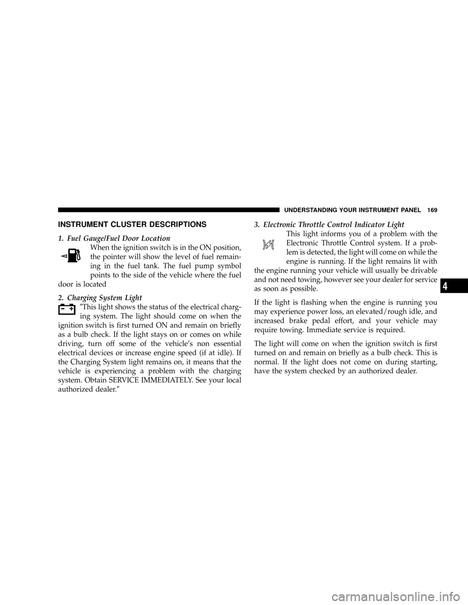
1. Fuel Gauge/Fuel Door Location
When the ignition switch is in the ON position,
the pointer will show the level of fuel remain-
ing in the fuel tank. The fuel pump symbol
points to the side of the vehicle where the fuel
door is located
2. Charging System Light
9This light shows the status of the electrical charg-
ing system. The light should come on when the
ignition switch is first turned ON and remain on briefly
as a bulb check. If the light stays on or comes on while
driving, turn off some of the vehicle's non essential
electrical devices or increase engine speed (if at idle). If
the Charging System light remains on, it means that the
vehicle is experiencing a problem with the charging
system. Obtain SERVICE IMMEDIATELY. See your local
authorized dealer.93. Electronic Throttle Control Indicator Light
This light informs you of a problem with the
Electronic Throttle Control system. If a prob-
lem is detected, the light will come on while the
engine is running. If the light remains lit with
the engine running your vehicle will usually be drivable
and not need towing, however see your dealer for service
as soon as possible.
If the light is flashing when the engine is running you
may experience power loss, an elevated/rough idle, and
increased brake pedal effort, and your vehicle may
require towing. Immediate service is required.
The light will come on when the ignition switch is first
turned on and remain on briefly as a bulb check. This is
normal. If the light does not come on during starting,
have the system checked by an authorized dealer.
UNDERSTANDING YOUR INSTRUMENT PANEL 169
4
Page 178 of 440
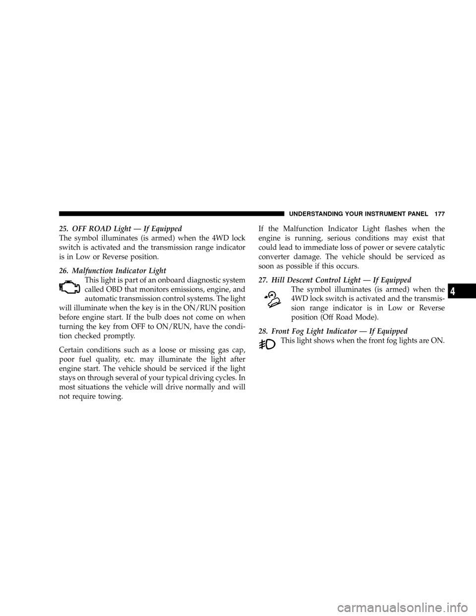
25. OFF ROAD Light Ð If Equipped
The symbol illuminates (is armed) when the 4WD lock
switch is activated and the transmission range indicator
is in Low or Reverse position.
26. Malfunction Indicator Light
This light is part of an onboard diagnostic system
called OBD that monitors emissions, engine, and
automatic transmission control systems. The light
will illuminate when the key is in the ON/RUN position
before engine start. If the bulb does not come on when
turning the key from OFF to ON/RUN, have the condi-
tion checked promptly.
Certain conditions such as a loose or missing gas cap,
poor fuel quality, etc. may illuminate the light after
engine start. The vehicle should be serviced if the light
stays on through several of your typical driving cycles. In
most situations the vehicle will drive normally and will
not require towing.If the Malfunction Indicator Light flashes when the
engine is running, serious conditions may exist that
could lead to immediate loss of power or severe catalytic
converter damage. The vehicle should be serviced as
soon as possible if this occurs.
27. Hill Descent Control Light Ð If Equipped
The symbol illuminates (is armed) when the
4WD lock switch is activated and the transmis-
sion range indicator is in Low or Reverse
position (Off Road Mode).
28. Front Fog Light Indicator Ð If Equipped
This light shows when the front fog lights are ON.
UNDERSTANDING YOUR INSTRUMENT PANEL 177
4
Page 227 of 440
NOTE:For maximum airflow to the rear seat passen-
gers, the center instrument panel outlets can be aimed, so
that the left center outlet is directed toward the right rear
passenger and the right center outlet is directed toward
the left rear passenger.
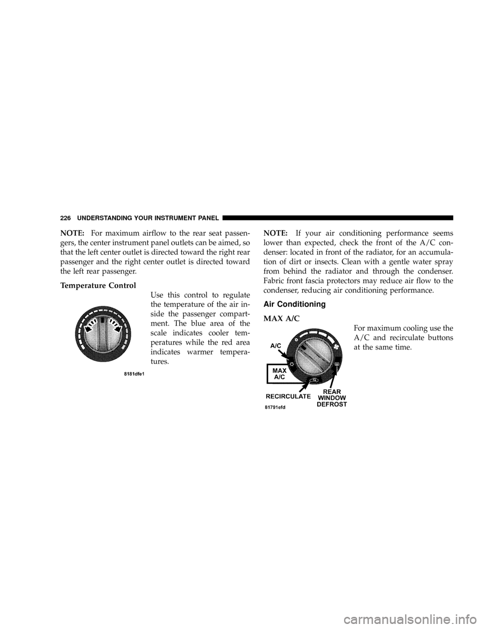
Temperature Control
Use this control to regulate
the temperature of the air in-
side the passenger compart-
ment. The blue area of the
scale indicates cooler tem-
peratures while the red area
indicates warmer tempera-
tures.NOTE:If your air conditioning performance seems
lower than expected, check the front of the A/C con-
denser: located in front of the radiator, for an accumula-
tion of dirt or insects. Clean with a gentle water spray
from behind the radiator and through the condenser.
Fabric front fascia protectors may reduce air flow to the
condenser, reducing air conditioning performance.
Air Conditioning
MAX A/C
For maximum cooling use the
A/C and recirculate buttons
at the same time.
226 UNDERSTANDING YOUR INSTRUMENT PANEL
Page 231 of 440
Window Fogging
Vehicle side windows tend to fog on the inside in mild
rainy or humid weather. To clear the windows, set mode
to the mix or defrost position. Direct the panel outlets
toward the side windows. Do not use recirculate without
A/C for long periods as fogging may occur.
Interior fogging on the windshield can be quickly re-
moved by using the defrost position.
If the fogging problem persists, clean the inside window
surfaces. The cause of undue fogging may be dirt collect-
ing on the inside surface of the glass.
NOTE:In cold weather, the use of the recircu-
late position will cause windows to fog on the
inside because of moisture build up inside thevehicle. For maximum defogging, press the recirculation
button until recirculate is off.
Summer Operation
Air conditioned vehicles must be protected with a high-
quality antifreeze coolant to provide proper corrosion
protection and to raise the boiling point of the coolant for
protection against overheating. A 50% concentration is
recommended.
Outside Air Intake
When operating the system during the winter months,
make sure the air intake, directly in front of the wind-
shield, is free of ice, slush, snow or other obstructions
such as leaves. Leaves collected in the air-intake plenum
may reduce air flow and plug the plenum water drains.
230 UNDERSTANDING YOUR INSTRUMENT PANEL
Page 232 of 440
The blower air will heat faster in cold weather if you use
only a low blower speed for the first few minutes of
vehicle operation.
Side Window Demisters
A side window demister outlet is at each end of the
instrument panel. These nonadjustable outlets direct airtoward the side windows when the system is in either the
FLOOR, MIX, or DEFROST mode. The air is directed at
the area of the windows through which you view the
outside mirrors.
UNDERSTANDING YOUR INSTRUMENT PANEL 231
4
Page 237 of 440
NFuel System Cautions..................305
NCarbon Monoxide Warnings..............306
mAdding Fuel..........................307
NFuel Filler Cap (Gas Cap)...............307
NLoose Fuel Filler Cap Message............308
mVehicle Loading........................309
NGross Vehicle Weight Rating (GVWR).......309
mTrailer Towing.........................309
NCommon Towing Definitions.............309NTrailer Hitch Classification...............312
NTrailer Towing Weights (Maximum Trailer Weight
Ratings)............................313
NTrailer And Tongue Weight..............314
NTowing Requirements..................315
NTowing Tips.........................320
mRecreational Towing (Behind Motorhome, Etc.) . . 322
NTowing This Vehicle Behind Another Vehicle
(Flat Towing With All Four Wheels On The
Ground)............................322
236 STARTING AND OPERATING
Page 239 of 440
Manual Transaxle
Before starting the engine fully apply the parking brake,
press the clutch pedal to the floor and place the gear
selector in NEUTRAL.
NOTE:The engine will not start unless the clutch pedal
is pressed to the floor.
NOTE:If key won't turn and steering wheel is locked,
rotate the wheel in either direction to relieve pressure on
the locking mechanism and then turn the key.
Normal Starting
Normal Starting of either a cold or a warm engine does
not require pumping or depressing the accelerator pedal.
Simply turn the ignition switch to the ªSTART'º position
and release when the engine starts. If the engine fails to
start within 15 seconds, turn the ignition switch to the
ªOFFº position, wait 10 to 15 seconds, then repeat the
normal starting procedure.
WARNING!
Do not attempt to push or tow your vehicle to get it
started. Vehicles equipped with an automatic trans-
axle cannot be started this way. Unburned fuel could
enter the catalytic converter and once the engine has
started, ignite and damage the converter and vehicle.
If the vehicle has a discharged battery, booster cables
may be used to obtain a start from another vehicle.
This type of start can be dangerous if done improp-
erly, so follow the procedure carefully. See section 6
of this manual for jump starting instructions.
Extremely Cold Weather (below220ÉF or229ÉC)
To insure reliable starting at these temperatures, use of an
externally powered electric engine block heater (available
from your dealer) is recommended.
238 STARTING AND OPERATING
Page 249 of 440
The package includes:
²2.4L DOHC 16-Valve I4 (172 bhp @ 6000 rpm, 165 lb-ft
@ 4400 rpm)
²Second generation continuously variable transaxle
(CVT2L) with 19:1 crawl ratio
²Tow Hooks: 2 front and 1 rear
²Front engine and transaxle skid plate
²Fuel tank skid plate
²Air filtration system
²Unique springs for a 1 inch of increased ride height
²Fog lamps
²Seat height adjust
²Three-mode Electronic Stability Program (ESP)
²Hill-descent control
²Unique off-road engine calibration for optimum off-
road performance with premium fuel
²Off-road Brake Traction Control
²Unique off-road Anti-lock brake calibration
²Heavy duty cooling package (Eng/larger CVT oil
cooler, High capacity cooling fans)
²Heavy duty alternator
²Improved body sealing and high located drivetrain
component vents
²Reinforced rear lateral links
Freedom Drive II 4WD System Operation
Under normal driving conditions, the vehicle operates in
the active four wheel drive mode. Pulling up on the 4WD
lock lever activates the 4WD system and lights the amber
4WD cluster light. This commands a higher torque to the
rear wheels, for improved traction capability on slippery
248 STARTING AND OPERATING