2007 ISUZU KB P190 Coolant sensor
[x] Cancel search: Coolant sensorPage 20 of 6020

0B-2 MAINTENANCE AND LUBRICATION
MAINTENANCE SCHEDULE (For GENERAL EXPORT)
Items followed by an asterisk (*) require more frequent maintenance if the vehicle is driven under severe conditions.
Replace the fuel filter (**Mark) when the fuel filter indicator light is lit.
Refer to "SEVERE CONDITIONS MAINTENANCE SCHEDULE."
I : Inspect and correct or replace as necessary A : Adjust
R : Replace or change T : Tighten to specified torque L : Lubricate
SERVICE INTERVAL: × 1,000 km 5 10 15 20 25 30 35 40 45 50 55 60 65 70 75 80 85 90 95 100(Use odometer reading × 1,000 miles 3 6 9 12 15 18 21 24 27 30 33 36 39 42 45 48 51 54 57 60or months whichever
comes first)
or months 6 12 18 24 30 36 42 48 54 60 66 72 78 84 90 96 102 108 114 120
ENGINE
Idling speed and acceleration
(GASOLINE) I I - I - I - I - I - I - I - I - I - I (DIESEL) I I I I I I I I I I I I I I I I I I I I * Air cleaner element
(GASOLINE) - I - I - I - R - I - I - I - R - I - I (DIESEL) I I I I I I I R I I I I I I I R I I I I * Engine oil (HFV6) - - R - - R - - R - - R - - R - - R - - (C24SE) Replace every 12,000km (4JH1-TC, 4JJ1 (Standard Output),
4JJ1 (High Output)) - R - R - R - R - R - R - R - R - R - R
(4JA1-T) R R R R R R R R R R R R R R R R R R R R * Engine oil filter (HFV6) - - R - - R - - R - - R - - R - - R - - (C24SE) Replace every 12,000km (4JH1-TC, 4JA1-T) - R - R - R - R - R - R - R - R - R - R (4JJ1 (Standard Output),
4JJ1 (High Output)) - - - R - - - R - - - R - - - R - - - R
Oil leakage and contamination (GASOLINE) - I - I - I - I - I - I - I - I - I - I (DIESEL) I I I I I I I I I I I I I I I I I I I I Fuel leakage
I I - I - I - I - I - I - I - I - I - I Fuel tank - - - I - - - I - - - I - - - I - - - I O2 Sensor (C24SE) Replace every 160,000km (HFV6)
MIL diagnostic Indicates O2 Sensor Valve clearances (6VE1) Check and adjust if noisy (4JH1-TC, 4JA1-T) A - - A - - - A - - - A - - - A - - - A (4JJ1 (Standard Output),
4JJ1 (High Output)) - - - - - - - A - - - - - - - A - - - -
Spark plugs (C24SE) (for leaded fuel
use) - R - R - R - R - R - R - R - R - R - R
Spark plugs (C24SE) (for unleaded
fuel use) - - - - - R - - - - - R - - - - - R - -
Spark plugs
(HFV6) Replace every 120,000km Spark plug wire - - - - - - - - - - - - - - - - - - - I Fuel filter (GASOLINE) - - - R - - - R - - - R - - - R - - - R (4JH1-TC, 4JA1-T) - - R - - R - - R - - R - - R - - R - - ** (4JJ1 (Standard Output),
4JJ1 (High Output)) Replace the fuel filter when the fuel filter indicator light is lit.
Fuel pump in fuel tank
(4JJ1 (Standard Output),
4JJ1 (High Output)) - - - - - - - I - - - - - - - I - - - -
Engine / Accessory drive belt
(C24SE) - - - - - - - - - I - - - - - - - - - I
(HFV6) Replace every 100,000km Fan belt tension and damage
(DIESEL) I I I I I I I I I I I I I I I I I I I I
* Exhaust system
I I - I - I - I - I - I - I - I - I - I Engine coolant concentration (HFV6) - I - I - I - I - I - I - I - I - I - R (C24SE) - I - I - I - I - R - I - I - I - I - R (DESEL) - I - I - I - I - I - I - I - I - I - I Engine coolant
(4JJ1 (Standard Output),
4JJ1 (High Output)) Change every 2 years
Cooling system for water leakage - I - I - I - I - I - I - I - I - I - I All hoses and pipes in engine
compartment for clogs or damage - I - I - I - I - I - I - I - I - I - I
Timing belt
(C24SE) - - - - - - - - - - - - - - - I - - - - Replace every 120,000km Timing belt (6VE1) Replace every 160,000km
BACK TO CHAPTER INDEX
TO MODEL INDEX
ISUZU KB P190 2007
Page 844 of 6020

ENGINE MECHANICAL 6A – 39
18. Radiator 1) Drain the engine coolant.
2) Remove the reservoir hose.
3) Remove the upper and lower hose.
4) Remove the fan guide.
5) Remove the radiator.
19. Fan
P1010034
20. Air cleaner
1) Remove the MAF sensor connector (4JA1TC/4JH1TC) from air cleaner duct.
2) Remove the air cleaner duct and the air cleaner box from engine room.
3) Remove the two air ducts from inter cooler (4JA1TC/4JH1TC).
21. Power Steering Pump Loosen the power steering pump adjust plate bolt, then
remove the power steering pump assembly. Place the
power steering pump assembly along with piping on the
body side.
22. Air conditioner compressor 1) Remove air compressor magnet connector.
2) Remove the air conditioner compressor. Place the air conditioner compressor along with piping on the body
side.
23. Engine Control Cable Remove the engine control cable from its bracket
(4JA1TC/4JH1TC) or the injection pump (4JA1T(L)).
24. Vacuum Piping Remove the vacuum pipe from the vacuum pump, the
EGR valve, injection pump FICD (4JA1T(L)).
25. Engine Harness 1) Remove following connectors from engine.
• TPS connector
• Oil pressure switch connector
• Thermo switch connector
• Injection pump connector
• Engine earth
• Thermometer unit connector
• TDC sensor
2) Remove the clips fixing engine harness.
P1010009
BACK TO CHAPTER INDEX
TO MODEL INDEX
ISUZU KB P190 2007
Page 951 of 6020

ENGINE COOLING 6B – 7
DIAGNOSIS
Engine Cooling Trouble
Symptom Possible Cause Action
Low Engine Coolant level Replenish
Thermo meter unit faulty Replace
Faulty thermostat Replace
Faulty Engine Coolant temperature
sensor Repair or replace
Clogged radiator
Clean or replace
Faulty radiator cap Replace
Low engine oil level or use of
improper engine oil Replenish or change oil
Clogged exhaust system
Clean exhaust system or replace
faulty parts
Faulty Throttle Position sensor Replace throttle valve assembly
Open or shorted Throttle Position
sensor circuit Repair or replace
Engine overheating
Damaged cylinder head gasket Replace
Engine overcooling Faulty thermostat Replace
Faulty thermostat Replace Engine slow to warm–up
Thermo unit faulty Replace
BACK TO CHAPTER INDEX
TO MODEL INDEX
ISUZU KB P190 2007
Page 1037 of 6020
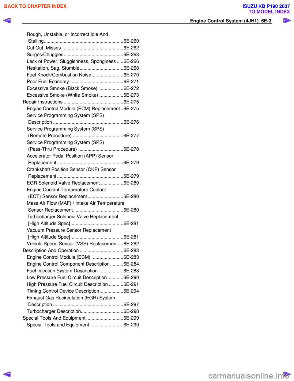
Engine Control System (4JH1) 6E-3
Rough, Unstable, or In co rr ect Idle And
Stallin g........................................................... .6E -260
Cut Out, Mi sses.............................................. .6E -262
Su rge s/Chuggle s............................................ .6E -263
La ck of Po wer, Sluggi shne ss, Spongine ss .... .6E -266
He sitation, Sag, Stu mble................................ .6E -268
Fuel Kno ck /Co mbu stion Noi se ....................... .6E -270
Poor F uel E cono my........................................ .6E -271
E xc ess ive S moke (B la ck S m oke) ................. .6E -272
E xc ess ive S moke (W hite S moke) ................. .6E -273
Repair In str u ctions ............................................ .6E -275
Engine Control Module (ECM) Replacement ..6E-275
Service Programming System (SPS)
Description .....................................................6E-276
Service Programming System (SPS)
(Remote Procedure) ......................................6E-277
Service Programming System (SPS)
(Pass-Thru Procedure) ..................................6E-278
Accelerator Pedal Position (APP) Sensor
Replacement ..................................................6E-279
Crankshaft Position Sensor (CKP) Sensor
Replacement ..................................................6E-279
EGR Solenoid Valve Replacement .................6E-280
Engine Coolant Temperature Coolant
(ECT) Sensor Replacement ...........................6E-280
Mass Air Flow (MAF) / Intake Air Temperature
Sensor Replacement......................................6E-280
Turbocharger Solenoid Valve Replacement
[High Altitude Spec] ........................................6E-281
Vacuum Pressure Sensor Replacement
[High Altitude Spec] ........................................6E-281
Vehicle Speed Sensor (VSS) Replacement ....6E-282
Description And Operation .................................6E-283 Engine Control Module (ECM) .......................6E-283
Engine Control Component Description ..........6E-284
Fuel Injection System Description ...................6E-288
Low Pressure Fuel Circuit Description ............6E-290
High Pressure Fuel Circuit Description ...........6E-291
Timing Control Device Description ..................6E-294
Exhaust Gas Recirculation (EGR) System
Description .....................................................6E-297
Turbocharger Description................................6E-298
Special Tools And Equipment ............................6E-299 Special Tools and Equipment .........................6E-299
BACK TO CHAPTER INDEX
TO MODEL INDEX
ISUZU KB P190 2007
Page 1054 of 6020
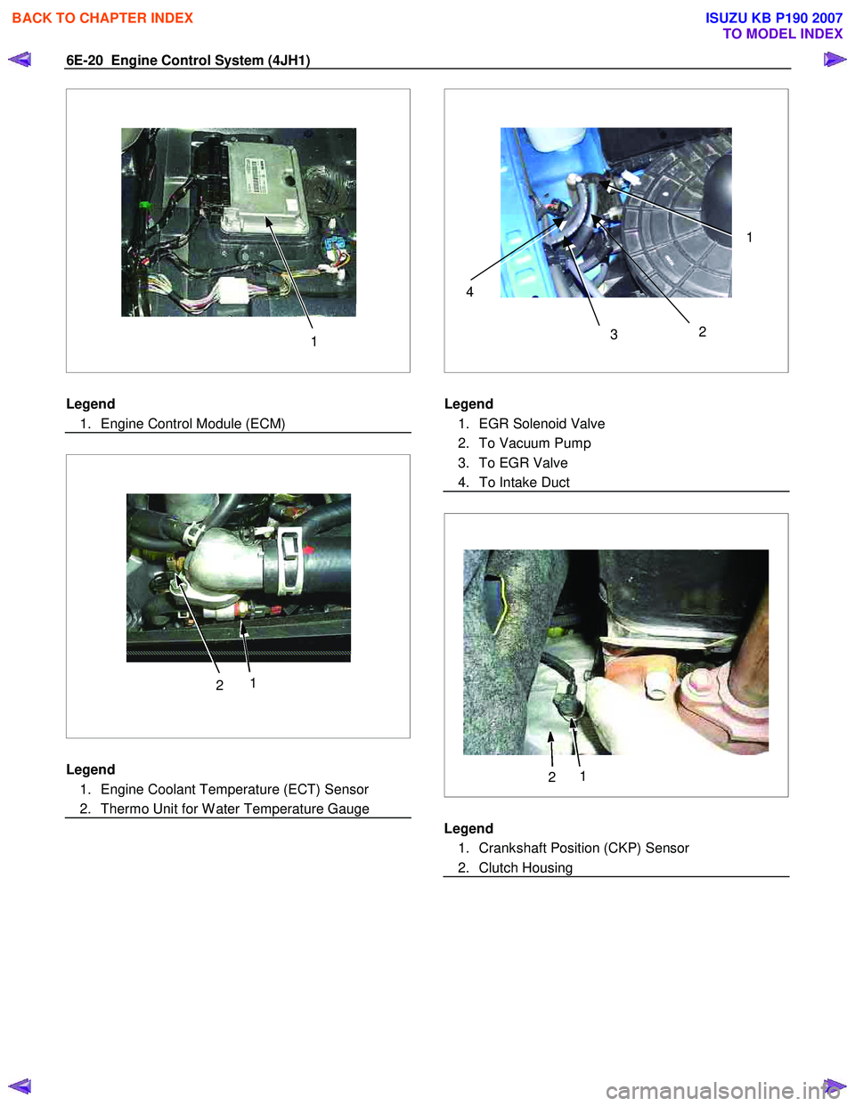
6E-20 Engine Control System (4JH1)
1
Legend
1. Engine Control Module (ECM)
2 1
Legend
1. Engine Coolant Temperature (ECT) Sensor
2. Thermo Unit for W ater Temperature Gauge
2
3 14
Legend
1. EGR Solenoid Valve
2. To Vacuum Pump
3. To EGR Valve
4. To Intake Duct
2 1
Legend
1. Crankshaft Position (CKP) Sensor
2. Clutch Housing
BACK TO CHAPTER INDEX
TO MODEL INDEX
ISUZU KB P190 2007
Page 1061 of 6020
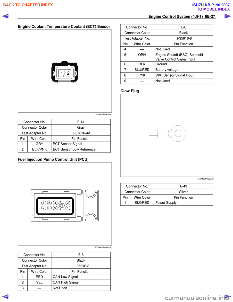
Engine Control System (4JH1) 6E-27
Engine Coolant Temperature Coolant (ECT) Sensor
LNW 46ESH003901
Connector No. E-41
Connector Color Gray
Test Adapter No. J-35616-4A
Pin W ire Color Pin Function
1 GRY ECT Sensor Signal
2 BLK/PNK ECT Sensor Low Reference
Fuel Injection Pump Control Unit (PCU)
RTW 66ESH000701
Connector No. E-6
Connector Color Black
Test Adapter No. J-35616-8
Pin W ire Color Pin Function
1 RED CAN Low Signal
2 YEL CAN High Signal
3
Not Used
Connector No. E-6
Connector Color Black
Test Adapter No. J-35616-8
Pin W ire Color Pin Function
4
Not Used
5 ORN Engine Shutoff (ESO) Solenoid
Valve Control Signal Input
6 BLK Ground
7 BLU/RED Battery voltage
8 PNK CKP Sensor Signal Input
9
Not Used
Glow Plug
LNW 46ESH000701
Connector No. E-49
Connector Color Silver
Pin W ire Color Pin Function
1 BLK/RED Power Supply
BACK TO CHAPTER INDEX
TO MODEL INDEX
ISUZU KB P190 2007
Page 1070 of 6020
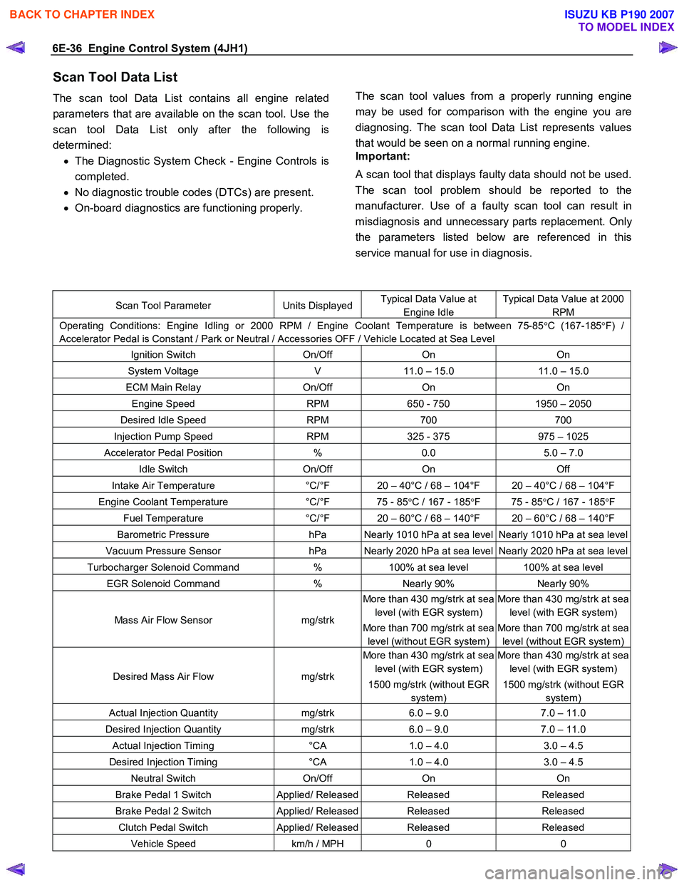
6E-36 Engine Control System (4JH1)
Scan Tool Data List
The scan tool Data List contains all engine related
parameters that are available on the scan tool. Use the
scan tool Data List only after the following is
determined: • The Diagnostic System Check - Engine Controls is
completed.
• No diagnostic trouble codes (DTCs) are present.
• On-board diagnostics are functioning properly.
The scan tool values from a properly running engine
may be used for comparison with the engine you are
diagnosing. The scan tool Data List represents values
that would be seen on a normal running engine.
Important:
A scan tool that displays faulty data should not be used.
The scan tool problem should be reported to the
manufacturer. Use of a faulty scan tool can result in
misdiagnosis and unnecessary parts replacement. Onl
y
the parameters listed below are referenced in this
service manual for use in diagnosis.
Scan Tool Parameter Units DisplayedTypical Data Value at
Engine Idle
Typical Data Value at 2000
RPM
Operating Conditions: Engine Idling or 2000 RPM / Engine Coolant Temperature is between 75-85 °C (167-185 °F) /
Accelerator Pedal is Constant / Park or Neutral / Accessories OFF / Vehicle Located at Sea Level
Ignition Switch On/Off On On
System Voltage V 11.0 – 15.0 11.0 – 15.0
ECM Main Relay On/Off On On
Engine Speed RPM 650 - 750 1950 – 2050
Desired Idle Speed RPM 700 700
Injection Pump Speed RPM 325 - 375 975 – 1025
Accelerator Pedal Position % 0.0 5.0 – 7.0
Idle Switch On/Off On Off
Intake Air Temperature °C/°F 20 – 40°C / 68 – 104°F 20 – 40°C / 68 – 104°F
Engine Coolant Temperature °C/°F 75 - 85 °C / 167 - 185 °F 75 - 85 °C / 167 - 185 °F
Fuel Temperature °C/°F 20 – 60°C / 68 – 140°F 20 – 60°C / 68 – 140°F
Barometric Pressure hPa Nearly 1010 hPa at sea level Nearly 1010 hPa at sea level
Vacuum Pressure Sensor hPa Nearly 2020 hPa at sea level Nearly 2020 hPa at sea level
Turbocharger Solenoid Command % 100% at sea level 100% at sea level
EGR Solenoid Command % Nearly 90% Nearly 90%
Mass Air Flow Sensor mg/strk
More than 430 mg/strk at sea
level (with EGR system)
More than 700 mg/strk at sea
level (without EGR system)
More than 430 mg/strk at sea
level (with EGR system)
More than 700 mg/strk at sea
level (without EGR system)
Desired Mass Air Flow mg/strk
More than 430 mg/strk at sea
level (with EGR system)
1500 mg/strk (without EGR
system)
More than 430 mg/strk at sea
level (with EGR system)
1500 mg/strk (without EGR
system)
Actual Injection Quantity mg/strk 6.0 – 9.0 7.0 – 11.0
Desired Injection Quantity mg/strk 6.0 – 9.0 7.0 – 11.0
Actual Injection Timing °CA 1.0 – 4.0 3.0 – 4.5
Desired Injection Timing °CA 1.0 – 4.0 3.0 – 4.5
Neutral Switch On/Off On On
Brake Pedal 1 Switch Applied/ ReleasedReleased Released
Brake Pedal 2 Switch Applied/ ReleasedReleased Released
Clutch Pedal Switch Applied/ ReleasedReleased Released
Vehicle Speed km/h / MPH 0 0
BACK TO CHAPTER INDEX
TO MODEL INDEX
ISUZU KB P190 2007
Page 1071 of 6020
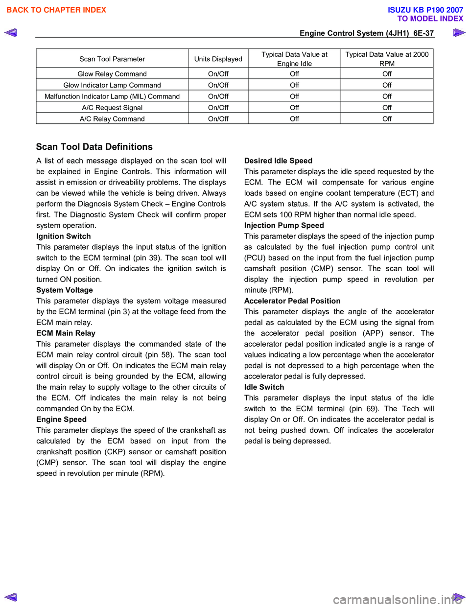
Engine Control System (4JH1) 6E-37
Scan Tool Parameter Units DisplayedTypical Data Value at
Engine Idle
Typical Data Value at 2000
RPM
Glow Relay Command On/Off Off Off
Glow Indicator Lamp Command On/Off Off Off
Malfunction Indicator Lamp (MIL) Command On/Off Off Off
A/C Request Signal On/Off Off Off
A/C Relay Command On/Off Off Off
Scan Tool Data Definitions
A list of each message displayed on the scan tool will
be explained in Engine Controls. This information will
assist in emission or driveability problems. The displays
can be viewed while the vehicle is being driven. Always
perform the Diagnosis System Check – Engine Controls
first. The Diagnostic System Check will confirm prope
r
system operation.
Ignition Switch
This parameter displays the input status of the ignition
switch to the ECM terminal (pin 39). The scan tool will
display On or Off. On indicates the ignition switch is
turned ON position.
System Voltage
This parameter displays the system voltage measured
by the ECM terminal (pin 3) at the voltage feed from the
ECM main relay.
ECM Main Relay
This parameter displays the commanded state of the
ECM main relay control circuit (pin 58). The scan tool
will display On or Off. On indicates the ECM main rela
y
control circuit is being grounded by the ECM, allowing
the main relay to supply voltage to the other circuits o
f
the ECM. Off indicates the main relay is not being
commanded On by the ECM.
Engine Speed
This parameter displays the speed of the crankshaft as
calculated by the ECM based on input from the
crankshaft position (CKP) sensor or camshaft position
(CMP) sensor. The scan tool will display the engine
speed in revolution per minute (RPM).
Desired Idle Speed
This parameter displays the idle speed requested by the
ECM. The ECM will compensate for various engine
loads based on engine coolant temperature (ECT) and
A/C system status. If the A/C system is activated, the
ECM sets 100 RPM higher than normal idle speed.
Injection Pump Speed
This parameter displays the speed of the injection pump
as calculated by the fuel injection pump control unit
(PCU) based on the input from the fuel injection pump
camshaft position (CMP) sensor. The scan tool will
display the injection pump speed in revolution pe
r
minute (RPM).
Accelerator Pedal Position
This parameter displays the angle of the accelerato
r
pedal as calculated by the ECM using the signal from
the accelerator pedal position (APP) sensor. The
accelerator pedal position indicated angle is a range o
f
values indicating a low percentage when the accelerator
pedal is not depressed to a high percentage when the
accelerator pedal is fully depressed.
Idle Switch
This parameter displays the input status of the idle
switch to the ECM terminal (pin 69). The Tech will
display On or Off. On indicates the accelerator pedal is
not being pushed down. Off indicates the accelerato
r
pedal is being depressed.
BACK TO CHAPTER INDEX
TO MODEL INDEX
ISUZU KB P190 2007