2007 ISUZU KB P190 check engine
[x] Cancel search: check enginePage 2455 of 6020
6F-6 ENGINE EXHAUST
Installation
To install, follow the removal steps in the reverse order.
Important - Installation
1. Front Exhaust Pipe Flange Nut
Connect the exhaust pipe to the exhaust manifold.
Front exhaust pipe to manifold nut.
Torque
N⋅m (kgf ⋅m)
28 (2.9)
Inspection
Make the necessary adjustments, and part replacements if
excessive wear or damage is discover during inspection.
1. Front Exhaust Pipe
2. Center Exhaust Pipe and Catalytic Converter Flange Nut
3. Exhaust Pipe Damper Rubber
4. Exhaust Silencer with Rear Exhaust Pipe
Check the pipes for for corrosion, cracking , damage or
misalignment and repair if required.
Check the damper rubber for deterioration or damage and
repair if required.
BACK TO CHAPTER INDEX
TO MODEL INDEX
ISUZU KB P190 2007
Page 2459 of 6020
6F-10 ENGINE EXHAUST
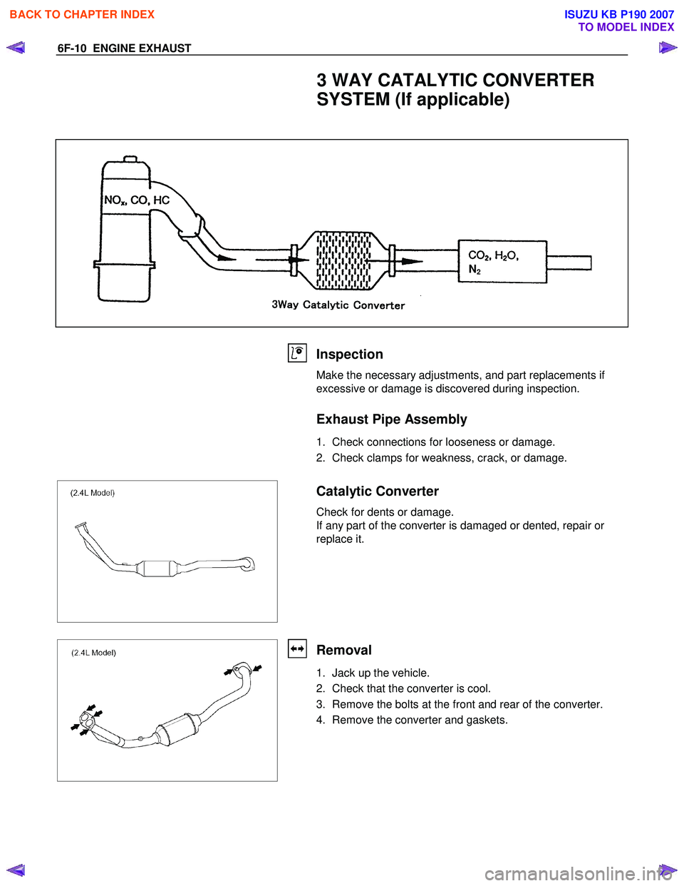
3 WAY CATALYTIC CONVERTER
SYSTEM (If applicable)
N2
Inspection
Make the necessary adjustments, and part replacements if
excessive or damage is discovered during inspection.
Exhaust Pipe Assembly
1. Check connections for looseness or damage.
2. Check clamps for weakness, crack, or damage.
Catalytic Converter
Check for dents or damage.
If any part of the converter is damaged or dented, repair or
replace it.
Removal
1. Jack up the vehicle.
2. Check that the converter is cool.
3. Remove the bolts at the front and rear of the converter.
4. Remove the converter and gaskets.
BACK TO CHAPTER INDEX
TO MODEL INDEX
ISUZU KB P190 2007
Page 2466 of 6020
6G-2 ENGINE LUBRICATION
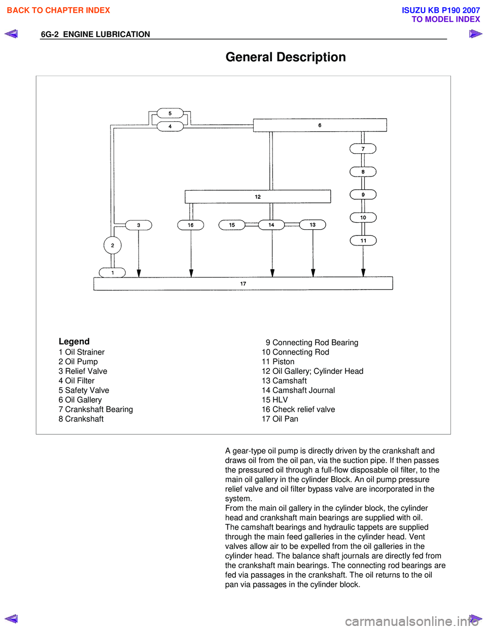
General Description
Legend
1 Oil Strainer
2 Oil Pump
3 Relief Valve
4 Oil Filter
5 Safety Valve
6 Oil Gallery
7 Crankshaft Bearing
8 Crankshaft 9 Connecting Rod Bearing
10 Connecting Rod
11 Piston
12 Oil Gallery; Cylinder Head
13 Camshaft
14 Camshaft Journal
15 HLV
16 Check relief valve
17 Oil Pan
A gear-type oil pump is directly driven by the crankshaft and
draws oil from the oil pan, via the suction pipe. If then passes
the pressured oil through a full-flow disposable oil filter, to the
main oil gallery in the cylinder Block. An oil pump pressure
relief valve and oil filter bypass valve are incorporated in the
system.
From the main oil gallery in the cylinder block, the cylinder
head and crankshaft main bearings are supplied with oil.
The camshaft bearings and hydraulic tappets are supplied
through the main feed galleries in the cylinder head. Vent
valves allow air to be expelled from the oil galleries in the
cylinder head. The balance shaft journals are directly fed from
the crankshaft main bearings. The connecting rod bearings are
fed via passages in the crankshaft. The oil returns to the oil
pan via passages in the cylinder block.
BACK TO CHAPTER INDEX
TO MODEL INDEX
ISUZU KB P190 2007
Page 2469 of 6020
ENGINE LUBRICATION 6G-5
Inspection and Repair
CAUTION: Make necessary correction or parts
replacement if wear, damage or any other abnormal
conditions are found through inspection.
Body and Gears
The pump assembly must be replaced if one or more of the
conditions below is discovered during inspection:
Indentation of gear pair - Use feeler strip and straight edge.
Dimension: 0.03 mm to 0.10 mm
(0.0012 to 0.0039 in)
Oil Strainer
Check the oil strainer for cracking and scoring. If cracking and
scoring are found, the oil strainer must be replaced.
Reassembly
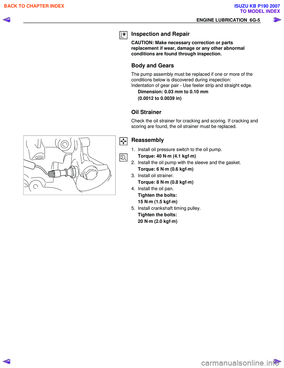
1. Install oil pressure switch to the oil pump.
Torque: 40 N ⋅
⋅⋅
⋅
m (4.1 kgf ⋅
⋅⋅
⋅
m)
2. Install the oil pump with the sleeve and the gasket.
Torque: 6 N ⋅
⋅⋅
⋅
m (0.6 kgf ⋅
⋅⋅
⋅
m)
3. Install oil strainer.
Torque: 8 N ⋅
⋅⋅
⋅
m (0.8 kgf ⋅
⋅⋅
⋅
m)
4. Install the oil pan.
Tighten the bolts:
15 N ⋅
⋅⋅
⋅
m (1.5 kgf ⋅
⋅⋅
⋅
m)
5. Install crankshaft timing pulley.
Tighten the bolts:
20 N ⋅
⋅⋅
⋅
m (2.0 kgf ⋅
⋅⋅
⋅
m)
BACK TO CHAPTER INDEX
TO MODEL INDEX
ISUZU KB P190 2007
Page 2475 of 6020
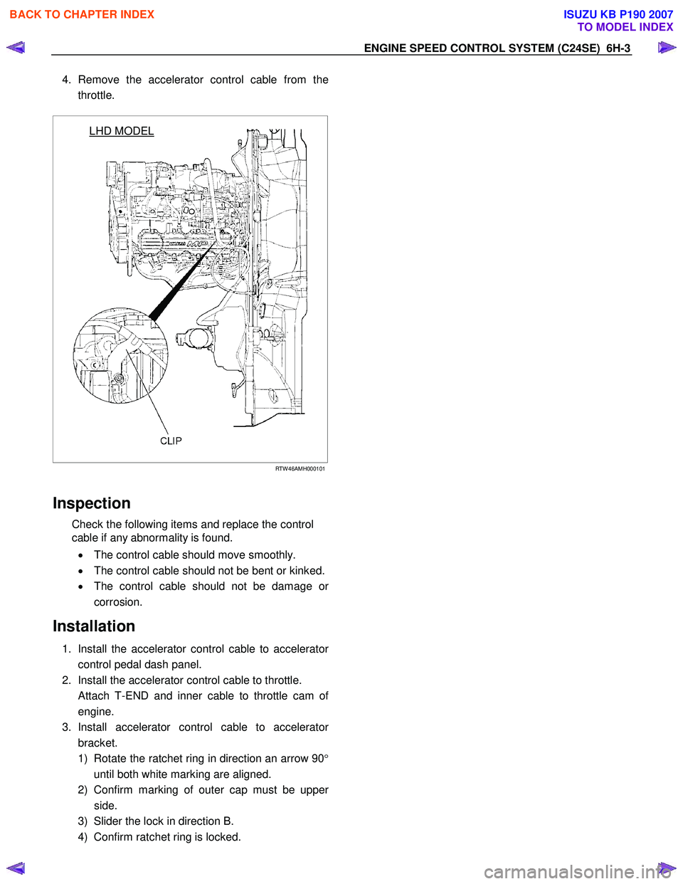
4. Remove the accelerator control cable from the
throttle.
LHD MODEL
RTW 46AMH000101
Inspection
Check the following items and replace the control
cable if any abnormality is found.
• The control cable should move smoothly.
• The control cable should not be bent or kinked.
• The control cable should not be damage o
r
corrosion.
Installation
1. Install the accelerator control cable to accelerator
control pedal dash panel.
2. Install the accelerator control cable to throttle.
Attach T-END and inner cable to throttle cam o
f
engine.
3. Install accelerator control cable to accelerato
r
bracket.
1) Rotate the ratchet ring in direction an arrow 90 °
until both white marking are aligned.
2) Confirm marking of outer cap must be uppe
r
side.
3) Slider the lock in direction B.
4) Confirm ratchet ring is locked.
EN
GIN E SPEED CONTR O L SY STEM (C 24SE) 6H-3
BACK TO CHAPTER INDEX
TO MODEL INDEX
ISUZU KB P190 2007
Page 2481 of 6020
Engine Mechanical – V6 Page 6A1–2
Visual / Physical Inspection ................................................................................................................................ 28
Intermittent ........................................................................................................................................................... 28
2.3 Engine Misfire without Internal Engine Noises .................................................................................. ............... 29
2.4 Engine Misfire with Abnormal Internal Lower Engine Noises...................................................................... .... 30
2.5 Engine Misfire with Abnormal Valve Train Noise .............................................................................................. 31
2.6 Engine Misfire with Coolant Consumption ........................................................................................................ 31
2.7 Engine Misfire with Excessive Oil Consumption .................................................................................. ............ 31
2.8 Engine Noise on Start-up, but only Lasting a Few Seconds ....................................................................... ..... 31
2.9 Upper Engine Noise, Regardless of Engine Speed........................................................................................... 33
2.10 Lower Engine Noise, Regardless of Engine Speed ................................................................................. ......... 34
2.11 Engine Noise Under Load ................................................................................................................................... 35
2.12 Engine Will Not Crank – Crankshaft Will Not Rotate ............................................................................. ........... 35
2.13 Coolant in Combustion Chamber ....................................................................................................................... 37
Definition .............................................................................................................................................................. 37
2.14 Coolant in Engine Oil.......................................................................................................... ................................. 37
Definition .............................................................................................................................................................. 37
2.15 Engine Compression Test ........................................................................................................ ........................... 38
Preliminary Steps................................................................................................................................................. 38
Engine Cylinder Compression Test ............................................................................................... .................... 38
Test Result Evaluation......................................................................................................................................... 38
2.16 Cylinder Leakage Test .......................................................................................................... ............................... 39
2.17 Engine Oil Consumption Diagnosis ............................................................................................... .................... 39
Definition .............................................................................................................................................................. 39
2.18 Engine Oil Leak Diagnosis ...................................................................................................... ............................ 40
Introduction .......................................................................................................................................................... 40
Locating and Identifying the Leak .............................................................................................. ........................ 40
Visual Inspection ................................................................................................................................................. 40
Powder Method .................................................................................................................. .................................. 40
Black Light and Dye Method ..................................................................................................... .......................... 40
Possible Causes for Engine Oil Leaks ........................................................................................... .................... 41
2.19 Engine Oil Pressure Diagnosis ........................................................................................................................... 42
2.20 Accessory Drive Belt Diagnosis ................................................................................................. ........................ 42
Tension Check ..................................................................................................................................................... 42
Inspect .................................................................................................................................................................. 42
Drive Belt Chirp .................................................................................................................................................... 43
Definition .......................................................................................................................................................... 43
Diagnostic Aids................................................................................................................................................. 43
Test Description ............................................................................................................... ................................ 43
Diagnostic Table............................................................................................................................................... 44
Drive Belt Squeal .............................................................................................................. ................................... 45
Definition .......................................................................................................................................................... 45
Diagnostic Aids................................................................................................................................................. 45
Test Description ............................................................................................................... ................................ 45
Diagnostic Table............................................................................................................................................... 46
Drive Belt Whine ............................................................................................................... ................................... 46
Definition .......................................................................................................................................................... 46
Diagnostic Aids................................................................................................................................................. 46
Test Description ............................................................................................................... ................................ 46
Diagnostic Table............................................................................................................................................... 47
Drive Belt Rumble .............................................................................................................. .................................. 47
Definition .......................................................................................................................................................... 47
Diagnostic Aids................................................................................................................................................. 48
Test Description ............................................................................................................... ................................ 48
Diagnostic Table............................................................................................................................................... 48
Drive Belt Vibration........................................................................................................... ................................... 49
Definition .......................................................................................................................................................... 49
Diagnostic Aids................................................................................................................................................. 49
Test Description ............................................................................................................... ................................ 49
Diagnostic Table............................................................................................................................................... 50
Drive Belt Falls Off ........................................................................................................... .................................... 50
BACK TO CHAPTER INDEX
TO MODEL INDEX
ISUZU KB P190 2007
Page 2482 of 6020
Engine Mechanical – V6 Page 6A1–3
Definition .......................................................................................................................................................... 50
Diagnostic Aids................................................................................................................................................. 50
Test Description ............................................................................................................... ................................ 50
Diagnostic Table............................................................................................................................................... 51
Drive Belt Excessive Wear ...................................................................................................... ............................ 51
Definition .......................................................................................................................................................... 51
Diagnostic Aids................................................................................................................................................. 52
Test Description ............................................................................................................... ................................ 52
Diagnostic Table............................................................................................................................................... 52
Accessory Drive Belt Tensioner Diagnosis ....................................................................................... ................ 52
Diagnostic Table............................................................................................................................................... 52
3 Minor Service Operations ....................................................................................................... .............53
3.1 Engine Oil ............................................................................................................................................................. 54
Check .................................................................................................................................................................... 54
Replace ........................................................................................................................ ......................................... 54
Pressure Check ................................................................................................................. ................................... 55
3.2 Oil Filter Cartridge ............................................................................................................................................... 56
Replace ................................................................................................................................................................. 56
3.3 Oil Filter Adaptor............................................................................................................. ..................................... 57
Remove ................................................................................................................................................................. 57
Reinstall ................................................................................................................................................................ 57
3.4 Oil Level Indicator Tube ....................................................................................................... ............................... 58
Remove ............................................................................................................................................................ 58
Reinstall ........................................................................................................................................................... 58
3.5 Accessory Drive Belt ........................................................................................................... ................................ 59
RWD Vehicle ......................................................................................................................................................... 59
Remove ............................................................................................................................................................ 59
Reinstall ........................................................................................................................................................... 59
3.6 Accessory Drive Belt Idler Pulley .............................................................................................. ......................... 60
Remove ............................................................................................................................................................ 60
Reinstall ........................................................................................................................................................... 60
3.7 Accessory Drive Belt Tensioner Assembly ........................................................................................ ............... 61
Remove ............................................................................................................................................................ 61
Reinstall ........................................................................................................................................................... 61
3.8 Power Steering Pump Bracket .................................................................................................... ........................ 62
Remove ................................................................................................................................................................. 62
Reinstall ................................................................................................................................................................ 62
3.9 Upper Intake Manifold.......................................................................................................... ................................ 62
Remove ................................................................................................................................................................. 63
Disassemble ......................................................................................................................................................... 66
Clean ..................................................................................................................................................................... 66
Inspect .................................................................................................................................................................. 66
Reassemble .......................................................................................................................................................... 67
Reinstall ...................................................................................................................... .......................................... 67
3.10 Intake Manifold Assembly – Complete............................................................................................ ................... 68
Remove ................................................................................................................................................................. 68
Disassemble ......................................................................................................................................................... 72
Clean ..................................................................................................................................................................... 73
Inspect .................................................................................................................................................................. 73
Reassemble .......................................................................................................................................................... 74
Reinstall ...................................................................................................................... .......................................... 74
3.11 Exhaust Manifold Assembly ...................................................................................................... ......................... 75
Remove ................................................................................................................................................................. 75
Inspect .................................................................................................................................................................. 77
Reinstall ................................................................................................................................................................ 77
3.12 Camshaft Cover ................................................................................................................. .................................. 79
Remove ................................................................................................................................................................. 79
Clean and Inspect .............................................................................................................. .................................. 81
BACK TO CHAPTER INDEX
TO MODEL INDEX
ISUZU KB P190 2007
Page 2494 of 6020
Engine Mechanical – V6 Page 6A1–15
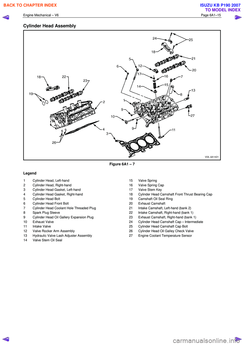
Cylinder Head Assembly
Figure 6A1 – 7
Legend
1 Cylinder Head, Left-hand
2 Cylinder Head, Right-hand
3 Cylinder Head Gasket, Left-hand
4 Cylinder Head Gasket, Right-hand
5 Cylinder Head Bolt
6 Cylinder Head Front Bolt
7 Cylinder Head Coolant Hole Threaded Plug
8 Spark Plug Sleeve
9 Cylinder Head Oil Gallery Expansion Plug
10 Exhaust Valve
11 Intake Valve
12 Valve Rocker Arm Assembly
13 Hydraulic Valve Lash Adjuster Assembly
14 Valve Stem Oil Seal 15 Valve Spring
16 Valve Spring Cap
17 Valve Stem Key
18 Cylinder Head Camshaft Front Thrust Bearing Cap
19 Camshaft Oil Seal Ring
20 Exhaust Camshaft
21 Intake Camshaft, Left-hand (bank 2)
22 Intake Camshaft, Right-hand (bank 1)
23 Exhaust Camshaft, Right-hand (bank 1)
24 Cylinder Head Camshaft Cap – Intermediate
25 Cylinder Head Camshaft Cap Bolt
26 Cylinder Head Oil Galley Check Valve
27 Engine Coolant Temperature Sensor
BACK TO CHAPTER INDEX
TO MODEL INDEX
ISUZU KB P190 2007