2007 ISUZU KB P190 Circuit
[x] Cancel search: CircuitPage 2404 of 6020
6E–234 ENGINE DRIVEABILITY AND EMISSIONS
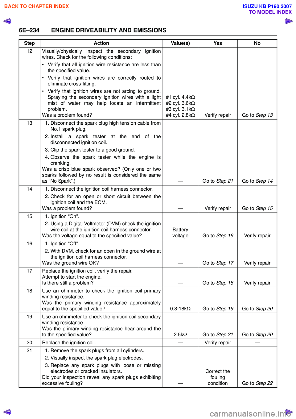
12 Visually/physically inspect the secondary ignitionwires. Check for the following conditions:
• Verify that all ignition wire resistance are less than the specified value.
• Verify that ignition wires are correctly routed to eliminate cross-fitting.
• Verify that ignition wires are not arcing to ground. Spraying the secondary ignition wires with a light
mist of water may help locate an intermittent
problem.
Was a problem found? #1 cyl. 4.4k
Ω
#2 cyl. 3.6k Ω
#3 cyl. 3.1k Ω
#4 cyl. 2.8k ΩVerify repair Go to Step 13
13 1. Disconnect the spark plug high tension cable from No.1 spark plug.
2. Install a spark tester at the end of the disconnected ignition coil.
3. Clip the spark tester to a good ground.
4. Observe the spark tester while the engine is cranking.
Was a crisp blue spark observed? (Only one or two
sparks followed by no result is considered the same
as “No Spark”.) — Go to Step 21Go to Step 14
14 1. Disconnect the ignition coil harness connector. 2. Check for an open or short circuit between theignition coil and the ECM.
Was a problem found? — Verify repair Go to Step 15
15 1. Ignition “On”. 2. Using a Digital Voltmeter (DVM) check the ignitionwire coil at the ignition coil harness connector.
Was the voltage equal to the specified value? Battery
voltage Go to Step 16Verify repair
16 1. Ignition “Off”. 2. With DVM, check for an open in the ground wire atthe ignition coil harness connector.
Was the ground wire OK? — Go to Step 17Verify repair
17 Replace the ignition coil, verify the repair. Attempt to start the engine.
Is there still a problem? — Go to Step 18Verify repair
18 Use an ohmmeter to check the ignition coil primary winding resistance.
Was the primary winding resistance approximately
equal to the specified value? 0.8-18kΩGo to Step 19 Go to Step 20
19 Use an ohmmeter to check the ignition coil secondary winding resistance.
Was the primary winding resistance hear around the
to the specified value? 2.5kΩ Go to Step 21 Go to Step 20
20 Replace the ignition coil. — Verify repair —
21 1. Remove the spark plugs from all cylinders. 2. Visually inspect the spark plug electrodes.
3. Replace any spark plugs with loose or missing electrodes or cracked insulators.
Did your inspection reveal any spark plugs exhibiting
excessive fouling? —Correct the
fouling
condition Go to Step 22
Step
Action Value(s) Yes No
BACK TO CHAPTER INDEX
TO MODEL INDEX
ISUZU KB P190 2007
Page 2405 of 6020
ENGINE DRIVEABILITY AND EMISSIONS 6E–235
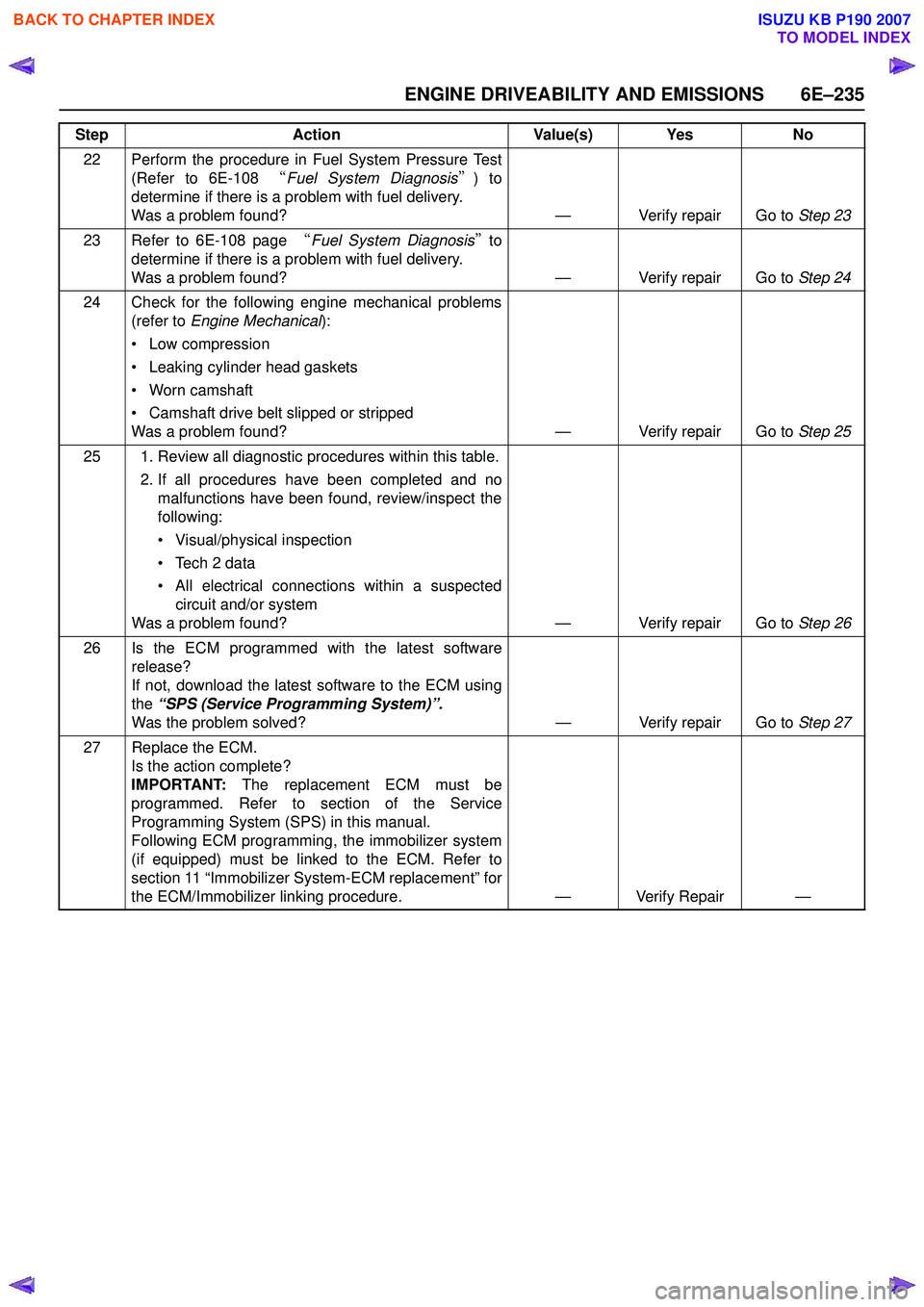
22 Perform the procedure in Fuel System Pressure Test(Refer to 6E-108 “Fuel System Diagnosis ”) to
determine if there is a problem with fuel delivery.
Was a problem found? — Verify repair Go to Step 23
23 Refer to 6E-108 page “Fuel System Diagnosis ” to
determine if there is a problem with fuel delivery.
Was a problem found? — Verify repair Go to Step 24
24 Check for the following engine mechanical problems (refer to Engine Mechanical ):
• Low compression
• Leaking cylinder head gaskets
• Worn camshaft
• Camshaft drive belt slipped or stripped
Was a problem found? — Verify repair Go to Step 25
25 1. Review all diagnostic procedures within this table. 2. If all procedures have been completed and nomalfunctions have been found, review/inspect the
following:
• Visual/physical inspection
• Tech 2 data
• All electrical connections within a suspected circuit and/or system
Was a problem found? — Verify repair Go to Step 26
26 Is the ECM programmed with the latest software release?
If not, download the latest software to the ECM using
the “SPS (Service Programming System)”.
Was the problem solved? — Verify repair Go to Step 27
27 Replace the ECM. Is the action complete?
IMPORTANT: The replacement ECM must be
programmed. Refer to section of the Service
Programming System (SPS) in this manual.
Following ECM programming, the immobilizer system
(if equipped) must be linked to the ECM. Refer to
section 11 “Immobilizer System-ECM replacement” for
the ECM/Immobilizer linking procedure. — Verify Repair —
Step
Action Value(s) Yes No
BACK TO CHAPTER INDEX
TO MODEL INDEX
ISUZU KB P190 2007
Page 2408 of 6020
6E–238 ENGINE DRIVEABILITY AND EMISSIONS
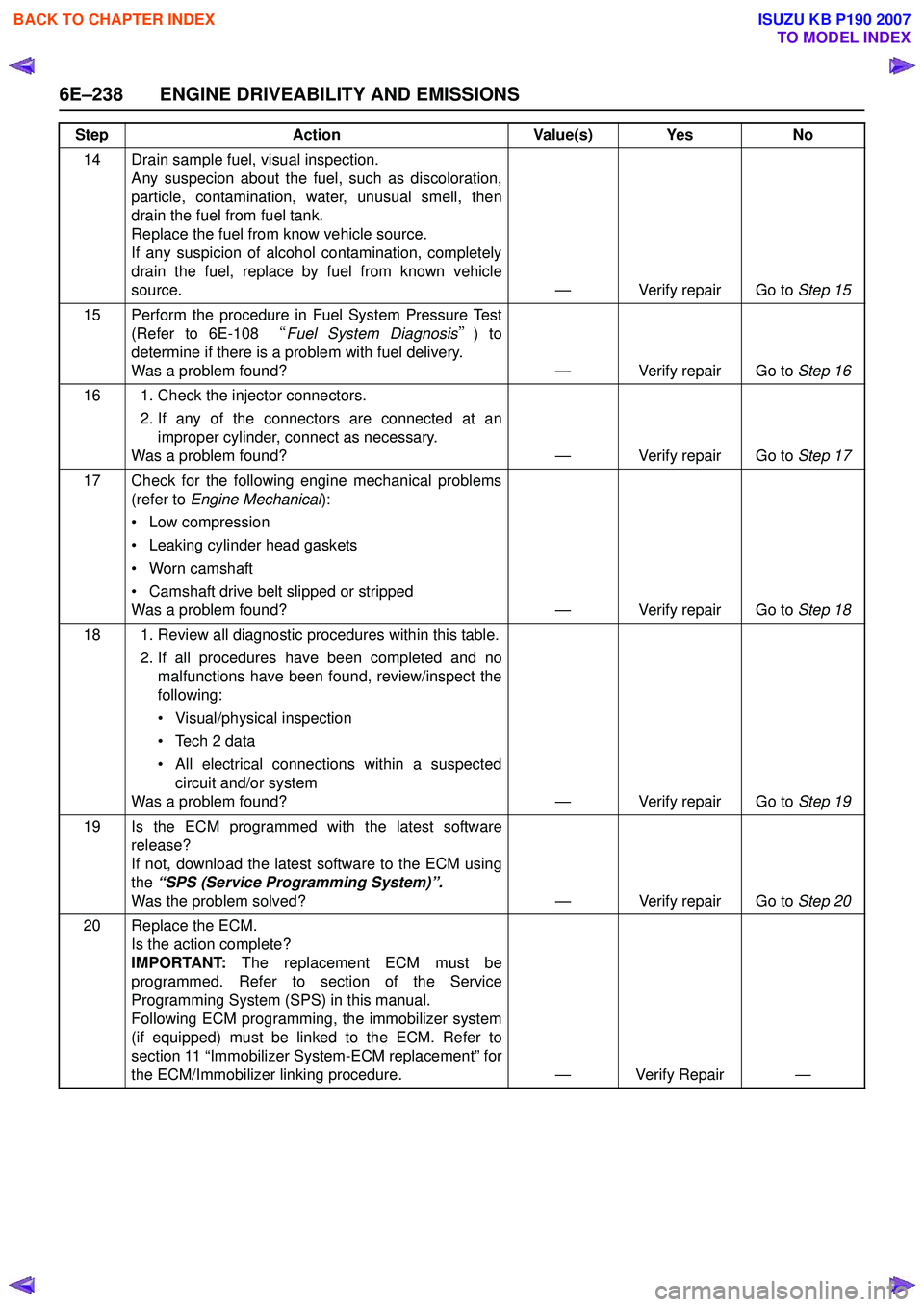
14 Drain sample fuel, visual inspection.Any suspecion about the fuel, such as discoloration,
particle, contamination, water, unusual smell, then
drain the fuel from fuel tank.
Replace the fuel from know vehicle source.
If any suspicion of alcohol contamination, completely
drain the fuel, replace by fuel from known vehicle
source. — Verify repair Go to Step 15
15 Perform the procedure in Fuel System Pressure Test (Refer to 6E-108 “Fuel System Diagnosis ”) to
determine if there is a problem with fuel delivery.
Was a problem found? — Verify repair Go to Step 16
16 1. Check the injector connectors. 2. If any of the connectors are connected at animproper cylinder, connect as necessary.
Was a problem found? — Verify repair Go to Step 17
17 Check for the following engine mechanical problems (refer to Engine Mechanical ):
• Low compression
• Leaking cylinder head gaskets
• Worn camshaft
• Camshaft drive belt slipped or stripped
Was a problem found? — Verify repair Go to Step 18
18 1. Review all diagnostic procedures within this table. 2. If all procedures have been completed and nomalfunctions have been found, review/inspect the
following:
• Visual/physical inspection
• Tech 2 data
• All electrical connections within a suspected circuit and/or system
Was a problem found? — Verify repair Go to Step 19
19 Is the ECM programmed with the latest software release?
If not, download the latest software to the ECM using
the “SPS (Service Programming System)”.
Was the problem solved? — Verify repair Go to Step 20
20 Replace the ECM. Is the action complete?
IMPORTANT: The replacement ECM must be
programmed. Refer to section of the Service
Programming System (SPS) in this manual.
Following ECM programming, the immobilizer system
(if equipped) must be linked to the ECM. Refer to
section 11 “Immobilizer System-ECM replacement” for
the ECM/Immobilizer linking procedure. — Verify Repair —
Step
Action Value(s) Yes No
BACK TO CHAPTER INDEX
TO MODEL INDEX
ISUZU KB P190 2007
Page 2411 of 6020
ENGINE DRIVEABILITY AND EMISSIONS 6E–241
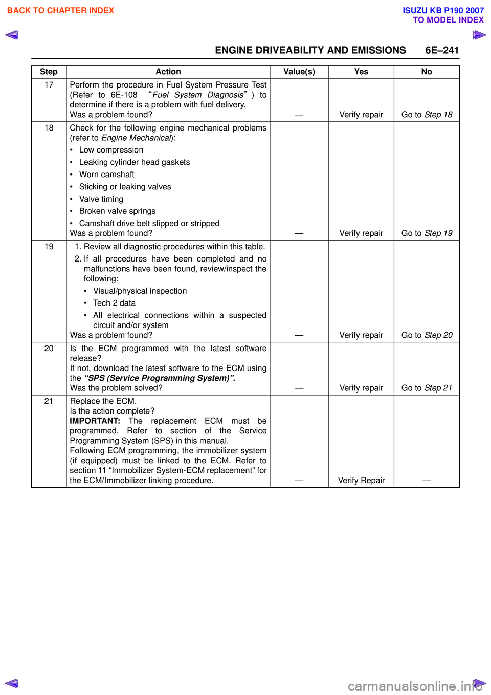
17 Perform the procedure in Fuel System Pressure Test(Refer to 6E-108 “Fuel System Diagnosis ”) to
determine if there is a problem with fuel delivery.
Was a problem found? — Verify repair Go to Step 18
18 Check for the following engine mechanical problems (refer to Engine Mechanical ):
• Low compression
• Leaking cylinder head gaskets
• Worn camshaft
• Sticking or leaking valves
• Valve timing
• Broken valve springs
• Camshaft drive belt slipped or stripped
Was a problem found? — Verify repair Go to Step 19
19 1. Review all diagnostic procedures within this table. 2. If all procedures have been completed and nomalfunctions have been found, review/inspect the
following:
• Visual/physical inspection
• Tech 2 data
• All electrical connections within a suspected circuit and/or system
Was a problem found? — Verify repair Go to Step 20
20 Is the ECM programmed with the latest software release?
If not, download the latest software to the ECM using
the “SPS (Service Programming System)”.
Was the problem solved? — Verify repair Go to Step 21
21 Replace the ECM. Is the action complete?
IMPORTANT: The replacement ECM must be
programmed. Refer to section of the Service
Programming System (SPS) in this manual.
Following ECM programming, the immobilizer system
(if equipped) must be linked to the ECM. Refer to
section 11 “Immobilizer System-ECM replacement” for
the ECM/Immobilizer linking procedure. — Verify Repair —
Step
Action Value(s) Yes No
BACK TO CHAPTER INDEX
TO MODEL INDEX
ISUZU KB P190 2007
Page 2414 of 6020
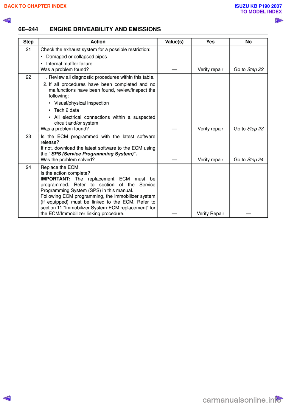
6E–244 ENGINE DRIVEABILITY AND EMISSIONS
21 Check the exhaust system for a possible restriction:• Damaged or collapsed pipes
• Internal muffler failure
Was a problem found? — Verify repair Go to Step 22
22 1. Review all diagnostic procedures within this table. 2. If all procedures have been completed and nomalfunctions have been found, review/inspect the
following:
• Visual/physical inspection
• Tech 2 data
• All electrical connections within a suspected circuit and/or system
Was a problem found? — Verify repair Go to Step 23
23 Is the ECM programmed with the latest software release?
If not, download the latest software to the ECM using
the “SPS (Service Programming System)”.
Was the problem solved? — Verify repair Go to Step 24
24 Replace the ECM. Is the action complete?
IMPORTANT: The replacement ECM must be
programmed. Refer to section of the Service
Programming System (SPS) in this manual.
Following ECM programming, the immobilizer system
(if equipped) must be linked to the ECM. Refer to
section 11 “Immobilizer System-ECM replacement” for
the ECM/Immobilizer linking procedure. — Verify Repair —
Step
Action Value(s) Yes No
BACK TO CHAPTER INDEX
TO MODEL INDEX
ISUZU KB P190 2007
Page 2417 of 6020
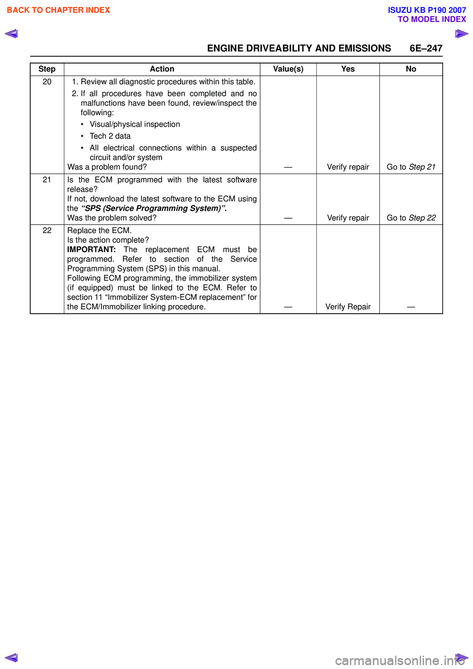
ENGINE DRIVEABILITY AND EMISSIONS 6E–247
20 1. Review all diagnostic procedures within this table.2. If all procedures have been completed and nomalfunctions have been found, review/inspect the
following:
• Visual/physical inspection
• Tech 2 data
• All electrical connections within a suspected circuit and/or system
Was a problem found? — Verify repair Go to Step 21
21 Is the ECM programmed with the latest software release?
If not, download the latest software to the ECM using
the “SPS (Service Programming System)”.
Was the problem solved? — Verify repair Go to Step 22
22 Replace the ECM. Is the action complete?
IMPORTANT: The replacement ECM must be
programmed. Refer to section of the Service
Programming System (SPS) in this manual.
Following ECM programming, the immobilizer system
(if equipped) must be linked to the ECM. Refer to
section 11 “Immobilizer System-ECM replacement” for
the ECM/Immobilizer linking procedure. — Verify Repair —
Step
Action Value(s) Yes No
BACK TO CHAPTER INDEX
TO MODEL INDEX
ISUZU KB P190 2007
Page 2418 of 6020
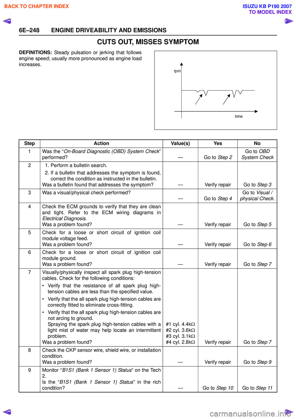
6E–248 ENGINE DRIVEABILITY AND EMISSIONS
CUTS OUT, MISSES SYMPTOM
DEFINITIONS: Steady pulsation or jerking that follows
engine speed; usually more pronounced as engine load
increases.
Step Action Value(s) Yes No
1 Was the “ On-Board Diagnostic (OBD) System Check ”
performed? — Go to Step 2Go to
OBD
System Check
2 1. Perform a bulletin search. 2. If a bulletin that addresses the symptom is found,correct the condition as instructed in the bulletin.
Was a bulletin found that addresses the symptom? — Verify repair Go to Step 3
3 Was a visual/physical check performed? —Go to Step 4Go to
Visual /
physical Check .
4 Check the ECM grounds to verify that they are clean and tight. Refer to the ECM wiring diagrams in
Electrical Diagnosis .
Was a problem found? — Verify repair Go to Step 5
5 Check for a loose or short circuit of ignition coil module voltage feed.
Was a problem found? — Verify repair Go to Step 6
6 Check for a loose or short circuit of ignition coil module ground.
Was a problem found? — Verify repair Go to Step 7
7 Visually/physically inspect all spark plug high-tension cables. Check for the following conditions:
• Verify that the resistance of all spark plug high- tension cables are less than the specified value.
• Verify that the all spark plug high-tension cables are correctly fitted to eliminate cross-fitting.
• Verify that the all spark plug high-tension cables are not arcing to ground.
Spraying the spark plug high-tension cables with a
light mist of water may help locate an intermittent
problem.
Was a problem found? #1 cyl. 4.4k
Ω
#2 cyl. 3.6k Ω
#3 cyl. 3.1k Ω
#4 cyl. 2.8k ΩVerify repair Go to Step 7
8 Check the CKP sensor wire, shield wire, or installation condition.
Was a problem found? — Verify repair Go to Step 9
9 Monitor “ B1S1 (Bank 1 Sensor 1) Status ” on the Tech
2.
Is the “ B1S1 (Bank 1 Sensor 1) Status ” in the rich
condition? — Go to Step 10Go to Step 11
BACK TO CHAPTER INDEX
TO MODEL INDEX
ISUZU KB P190 2007
Page 2420 of 6020
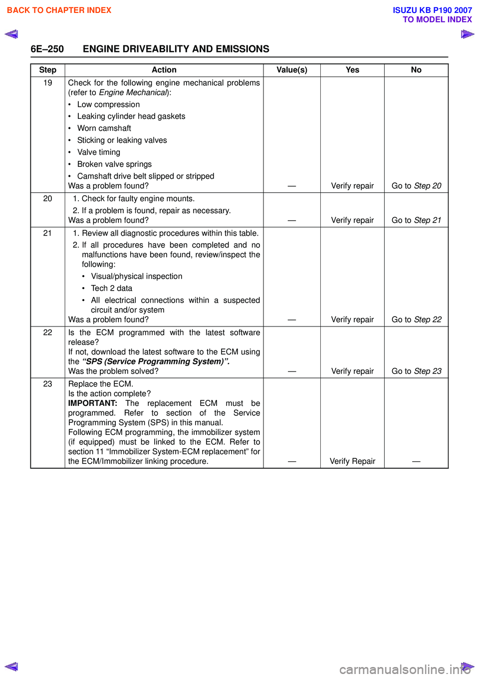
6E–250 ENGINE DRIVEABILITY AND EMISSIONS
19 Check for the following engine mechanical problems(refer to Engine Mechanical ):
• Low compression
• Leaking cylinder head gaskets
• Worn camshaft
• Sticking or leaking valves
• Valve timing
• Broken valve springs
• Camshaft drive belt slipped or stripped
Was a problem found? — Verify repair Go to Step 20
20 1. Check for faulty engine mounts. 2. If a problem is found, repair as necessary.
Was a problem found? — Verify repair Go to Step 21
21 1. Review all diagnostic procedures within this table. 2. If all procedures have been completed and nomalfunctions have been found, review/inspect the
following:
• Visual/physical inspection
• Tech 2 data
• All electrical connections within a suspected circuit and/or system
Was a problem found? — Verify repair Go to Step 22
22 Is the ECM programmed with the latest software release?
If not, download the latest software to the ECM using
the “SPS (Service Programming System)”.
Was the problem solved? — Verify repair Go to Step 23
23 Replace the ECM. Is the action complete?
IMPORTANT: The replacement ECM must be
programmed. Refer to section of the Service
Programming System (SPS) in this manual.
Following ECM programming, the immobilizer system
(if equipped) must be linked to the ECM. Refer to
section 11 “Immobilizer System-ECM replacement” for
the ECM/Immobilizer linking procedure. — Verify Repair —
Step
Action Value(s) Yes No
BACK TO CHAPTER INDEX
TO MODEL INDEX
ISUZU KB P190 2007