2007 ISUZU KB P190 sensor
[x] Cancel search: sensorPage 2498 of 6020
Engine Mechanical – V6 Page 6A1–19
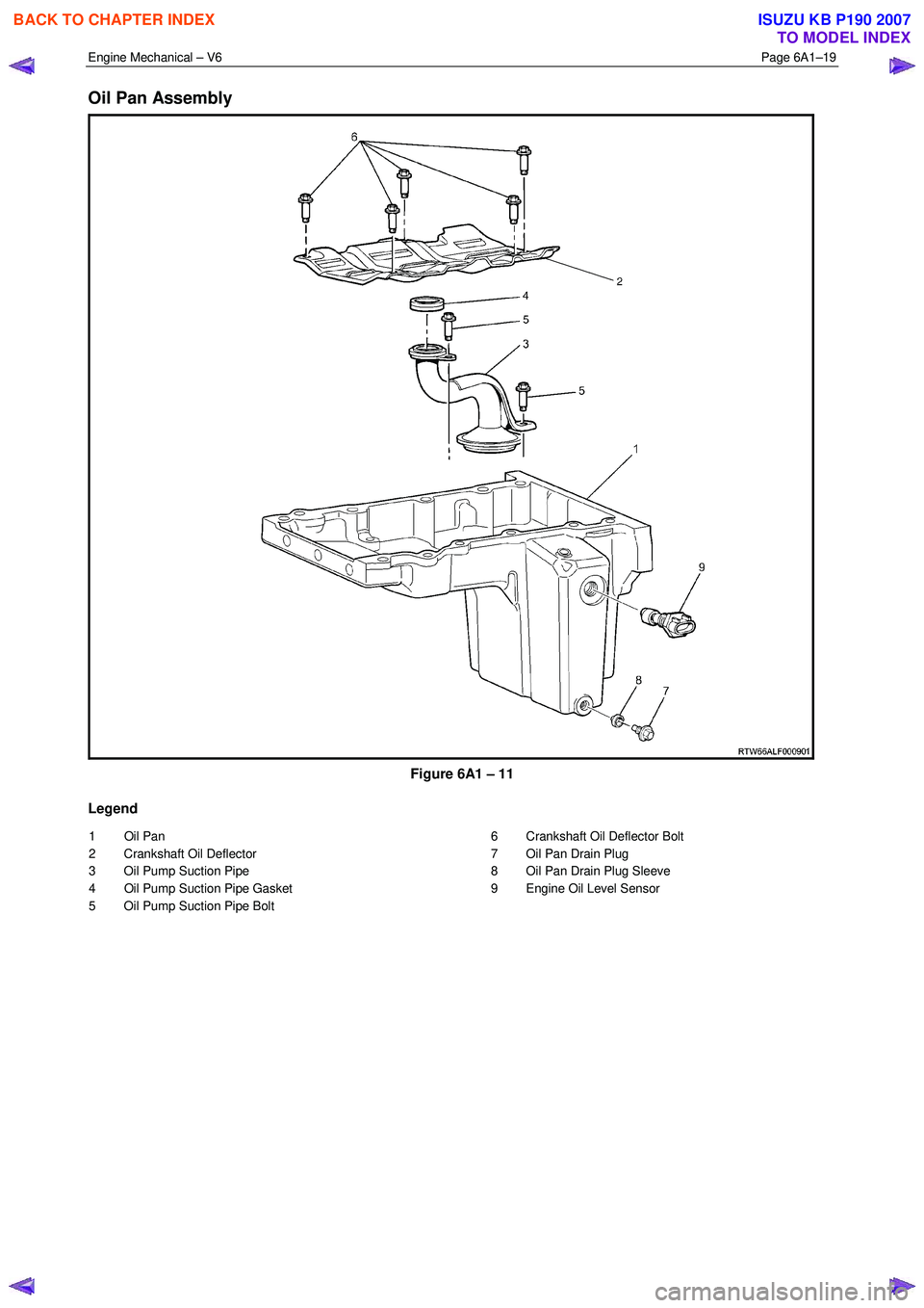
Oil Pan Assembly
Figure 6A1 – 11
Legend
1 Oil Pan
2 Crankshaft Oil Deflector
3 Oil Pump Suction Pipe
4 Oil Pump Suction Pipe Gasket
5 Oil Pump Suction Pipe Bolt 6 Crankshaft Oil Deflector Bolt
7 Oil Pan Drain Plug
8 Oil Pan Drain Plug Sleeve
9 Engine Oil Level Sensor
BACK TO CHAPTER INDEX
TO MODEL INDEX
ISUZU KB P190 2007
Page 2503 of 6020
Engine Mechanical – V6 Page 6A1–24
1.5 Engine Lubrication System
Lubrication Description
A structural diecast aluminium oil pan is fitted that incorporates an oil suction pipe, an oil deflector and an oil level sensor.
The oil suction pipe is bolted into the oil pan and seals to the bottom of the cylinder block with a gasket. The oil deflector
is bolted to the upper portion of the oil pan and ensures oil supply is maintained under all conditions. The oil level sensor
is mounted through the bottom of the oil pan.
A crankshaft driven gerotor oil pump is mounted to the front of the cylinder block. The pump, which incorporates an
internal pressure-relief valve, draws oil from the oil suction tube through the lower passage in the cylinder block. Oil is
then directed through an upper passage to the left-hand side of the cylinder block where the oil filter adapter is mounted.
The oil filter adapter incorporates a top-access, cartridge style oil filter. The filter is accessed through a screw-on cap tha t
incorporates an oil bypass valve. The oil filter adapter housing incorporates a drain back control valve and a threaded oil
pressure sender. Oil flows through a lower passage within the oil filter adapter and through the oil filter cartridge. Filtered
oil travels back through the upper passage of the adapter and into the engine block.
Oil is then directed up and across the front of the cylinder block, through several drilled passages. These front passages
feed oil to each cylinder head, the passage for the main bearings and piston oil jets, the right-hand and left-hand
secondary idler sprockets and to the primary timing chain tensioner.
Each cylinder head passage directs oil into oiling circuits for the stationary hydraulic lash adjusters (SHLAs) and the
camshaft bearing journals. An additional passage in the cylinder head also directs oil to the secondary timing chain
tensioner.
The oil passage that supplies oil to the main bearings also supplies oil to pressure actuated piston cooling oil jets. Each
oil jet is mounted between opposing cylinder bores and directs oil to the two bores to provide extra cooling and control
piston temperatures.
From the front passages, oil is directed to the front of the block where the right-hand and left-hand intermediate drive
shaft sprockets and the primary timing chain tensioner are mounted. Each camshaft timing chain tensioner relies on a
gasket to maintain an oil reserve after the engine is turned off. All camshaft timing chain tensioners incorporate a small
oil jet to supply an oil spray onto the camshaft timing chain components.
Oil returns to the oil pan, either through the camshaft timing chain area or through the drain back passages on the
outboard walls of the cylinder heads and cylinder block.
1.6 Service Notes
Cleanliness and Care
Throughout this Section, correct cleaning and protection of machined surfaces and friction areas is a part of the repair
procedure. This is considered standard workshop practice, even if not specifically stated.
W hen any internal engine part is serviced, care and cleanliness is extremely important.
W hen components are removed for service, they should be marked, organised or retained in a specific order for
reassembly.
At the time of installation, components should be installed in the same location and with the same mating surface as
when removed.
Any engine is a combination of many machined, honed, polished and lapped surfaces with tolerances that are measured
in thousandths of a millimetre. These surfaces should be covered or protected to avoid component damage.
A liberal coating of clean engine oil should be applied to friction areas during assembly, as the lubrication will protect and
lubricate friction surfaces during the initial engine start-up.
Replacing Engine Gaskets
Re-Using Gaskets and Applying Sealants
• do not reuse any gasket unless specified,
• gaskets that can be reused will be identified in the service procedure, and
• do not apply sealant to any gasket or sealing surface unless specified in the service information.
Separating Components
• Use a rubber mallet to separate components.
• Bump the part sideways to loosen the components.
• Bumping should be done at bends or reinforced areas to prevent distortion of parts.
Cleaning Gasket Surfaces
• W here required, remove all gasket and sealing material from the part using a plastic or wood scraper.
• Care must be used to avoid gouging or scraping the sealing surfaces.
BACK TO CHAPTER INDEX
TO MODEL INDEX
ISUZU KB P190 2007
Page 2508 of 6020
Engine Mechanical – V6 Page 6A1–29
2.3 Engine Misfire without Internal Engine
Noises
Cause Correction
Abnormalities, severe cracking, bumps or missing areas in
the accessory drive belt.
Abnormalities in the accessory drive system and/or
components may cause engine speed variations that result
in a misfire diagnostic trouble code (DTC). A misfire code
may be present without an actual misfire condition. Replace the accessory drive belt, refer to 3.5
Accessory
Drive Belt.
Refer to 6C1-2 Engine Management – V6 – Diagnostics to
check for DTCs.
W orn, damaged or misaligned accessory drive components
and excessive pulley run-out may lead to a misfire DTC.
A misfire code may be present without an actual misfire
condition. Inspect the components and repair or replace as required.
Refer to 6C1-2 Engine Management – V6 – Diagnostics to
check for DTCs.
Loose or incorrectly fitted flexplate or crankshaft balancer
assembly.
A misfire DTC may be present without an actual misfire
condition. Repair or replace the flexplate or crankshaft balancer as
required, refer to 3.13 Crankshaft Balancer Assembly
or 4.3 Flexplate Assembly.
Refer to 6C1-2 Engine Management – V6 – Diagnostics to
check for DTCs
Restricted exhaust system.
A severe restriction in the exhaust flow can cause
significant loss of engine performance and may set a DTC.
Possible causes of restrictions in the exhaust system
include collapsed/dented pipes and blocked mufflers and/or
catalytic converters. Repair or replace exhaust system components as required,
refer to 8B Exhaust System.
Refer to 6C1-2 Engine Management – V6 – Diagnostics to
check for DTCs
Incorrectly installed or damaged vacuum hoses. Repair or replace vacuum hoses as required.
Incorrect sealing between the intake manifold and cylinder
heads, upper intake manifold and lower intake manifold,
throttle body and intake manifold. Repair or replace the intake manifold, throttle body gaskets,
cylinder heads, throttle body as required.
Incorrectly installed or damaged barometric
pressure(BARO) sensor and/or seal. The seal should not
be torn or damaged. Repair or replace the BARO sensor and/or seal as
required, refer to 6C1-3 Engine Management – V6 –
Service Operations.
Incorrectly installed or damaged EVAP purge solenoid
and/or O-ring seal. Repair or replace the EVAP purge solenoid and/or seal as
required, refer to 6C1-3 Engine Management – V6 –
Service Operations
W orn or loose stationary hydraulic lash adjusters (SHLA)
and/or rocker arms.
The SHLAs, rocker arms and roller bearings should be
intact and in the correct position. Replace the SHLAs and/or rocker arms as required, refer to
3.21 Stationary Hydraulic Lash Adjuster or 3.20
Rocker Arm.
Stuck valves.
Carbon build up on the valve stems can result in the valves
not closing correctly. Repair or replace as required, refer to 3.22 Cylinder Head
Assembly.
Excessively worn or misaligned timing chain/s. Replace the timing chain/s and components as required,
refer to 3.16 Timing Chains, Tensioners, Shoes and
Guides.
W orn camshaft lobes. Replace the camshaft/s and SHLAs as required, refer to
3.19 Camshaft or 3.21 Stationary Hydraulic Lash
Adjuster.
Excessive oil pressure.
A lubrication system with excessive oil pressure may lead
to excessive lash adjuster pump-up and loss of
compression. 1 Perform an oil pressure test, refer to 3.1
Engine Oil.
2 Repair or replace the engine oil pump as required, refer to 3.17 Oil Pump Assembly.
BACK TO CHAPTER INDEX
TO MODEL INDEX
ISUZU KB P190 2007
Page 2534 of 6020
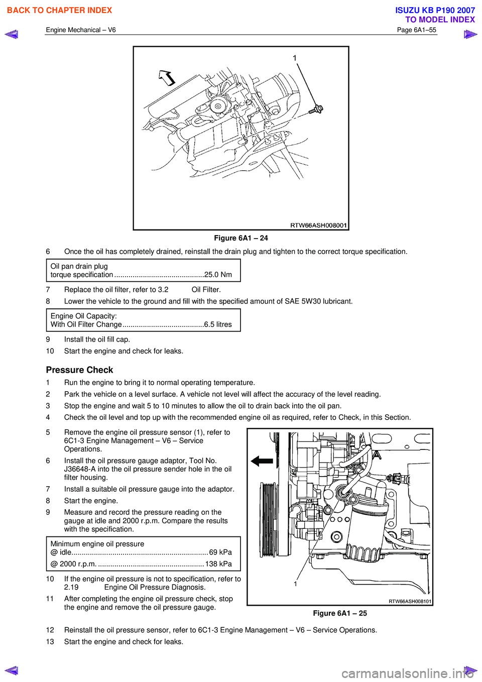
Engine Mechanical – V6 Page 6A1–55
Figure 6A1 – 24
6 Once the oil has completely drained, reinstall the drain plug and tighten to the correct torque specification.
Oil pan drain plug
torque specification ............................................25.0 Nm
7 Replace the oil filter, refer to 3.2 Oil Filter.
8 Lower the vehicle to the ground and fill with the specified amount of SAE 5W 30 lubricant.
Engine Oil Capacity:
With Oil Filter Change ........................................6.5 litres
9 Install the oil fill cap.
10 Start the engine and check for leaks.
Pressure Check
1 Run the engine to bring it to normal operating temperature.
2 Park the vehicle on a level surface. A vehicle not level will affect the accuracy of the level reading.
3 Stop the engine and wait 5 to 10 minutes to allow the oil to drain back into the oil pan.
4 Check the oil level and top up with the recommended engine oil as required, refer to Check, in this Section.
5 Remove the engine oil pressure sensor (1), refer to 6C1-3 Engine Management – V6 – Service
Operations.
6 Install the oil pressure gauge adaptor, Tool No. J36648-A into the oil pressure sender hole in the oil
filter housing.
7 Install a suitable oil pressure gauge into the adaptor.
8 Start the engine.
9 Measure and record the pressure reading on the gauge at idle and 2000 r.p.m. Compare the results
with the specification.
Minimum engine oil pressure
@ idle................................................................... 69 kPa
@ 2000 r.p.m. .................................................... 138 kPa
10 If the engine oil pressure is not to specification, refer to 2.19 Engine Oil Pressure Diagnosis.
11 After completing the engine oil pressure check, stop the engine and remove the oil pressure gauge.
Figure 6A1 – 25
12 Reinstall the oil pressure sensor, refer to 6C1-3 Engine Management – V6 – Service Operations.
13 Start the engine and check for leaks.
BACK TO CHAPTER INDEX
TO MODEL INDEX
ISUZU KB P190 2007
Page 2544 of 6020
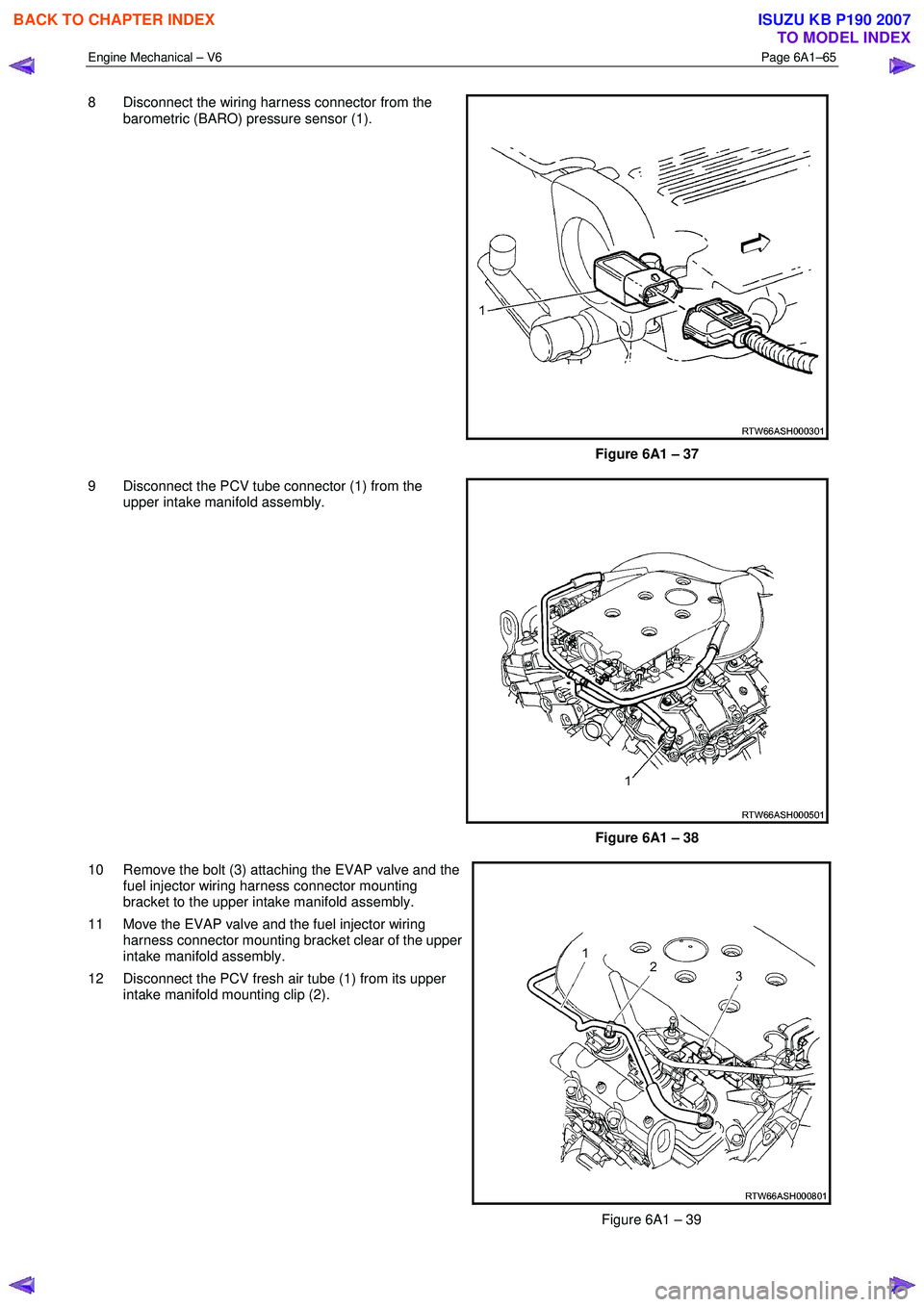
Engine Mechanical – V6 Page 6A1–65
8 Disconnect the wiring harness connector from the
barometric (BARO) pressure sensor (1).
Figure 6A1 – 37
9 Disconnect the PCV tube connector (1) from the upper intake manifold assembly.
Figure 6A1 – 38
10 Remove the bolt (3) attaching the EVAP valve and the fuel injector wiring harness connector mounting
bracket to the upper intake manifold assembly.
11 Move the EVAP valve and the fuel injector wiring harness connector mounting bracket clear of the upper
intake manifold assembly.
12 Disconnect the PCV fresh air tube (1) from its upper intake manifold mounting clip (2).
Figure 6A1 – 39
BACK TO CHAPTER INDEX
TO MODEL INDEX
ISUZU KB P190 2007
Page 2545 of 6020
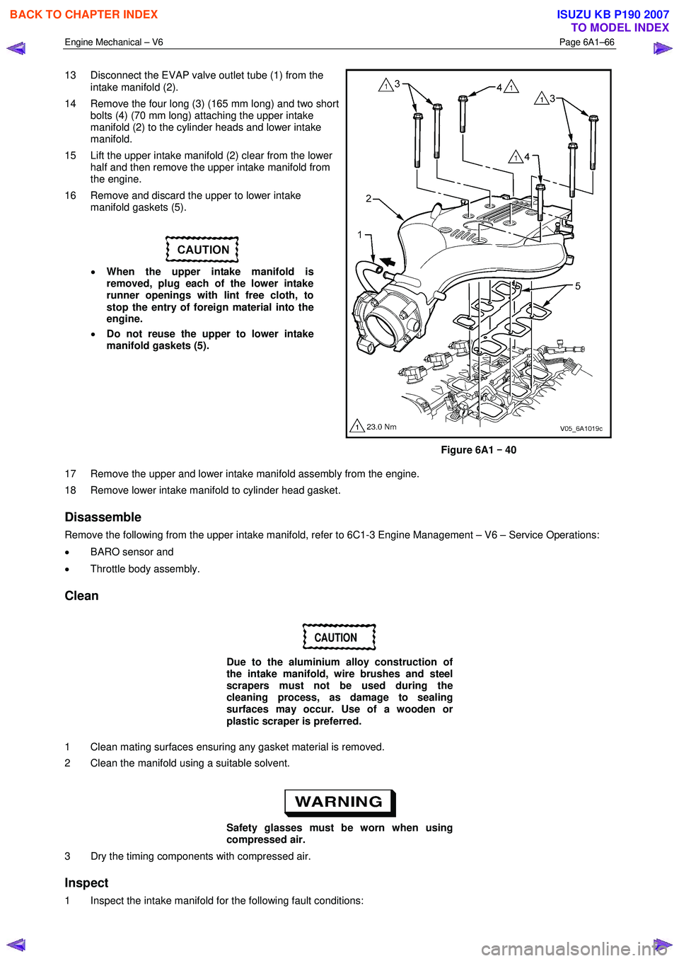
Engine Mechanical – V6 Page 6A1–66
13 Disconnect the EVAP valve outlet tube (1) from the
intake manifold (2).
14 Remove the four long (3) (165 mm long) and two short bolts (4) (70 mm long) attaching the upper intake
manifold (2) to the cylinder heads and lower intake
manifold.
15 Lift the upper intake manifold (2) clear from the lower half and then remove the upper intake manifold from
the engine.
16 Remove and discard the upper to lower intake manifold gaskets (5).
• When the upper intake manifold is
removed, plug each of the lower intake
runner openings with lint free cloth, to
stop the entry of foreign material into the
engine.
• Do not reuse the upper to lower intake
manifold gaskets (5).
Figure 6A1 –
––
–
40
17 Remove the upper and lower intake manifold assembly from the engine.
18 Remove lower intake manifold to cylinder head gasket.
Disassemble
Remove the following from the upper intake manifold, refer to 6C1-3 Engine Management – V6 – Service Operations:
• BARO sensor and
• Throttle body assembly.
Clean
CAUTION
Due to the aluminium alloy construction of
the intake manifold, wire brushes and steel
scrapers must not be used during the
cleaning process, as damage to sealing
surfaces may occur. Use of a wooden or
plastic scraper is preferred.
1 Clean mating surfaces ensuring any gasket material is removed.
2 Clean the manifold using a suitable solvent.
Safety glasses must be worn when using
compressed air.
3 Dry the timing components with compressed air.
Inspect
1 Inspect the intake manifold for the following fault conditions:
BACK TO CHAPTER INDEX
TO MODEL INDEX
ISUZU KB P190 2007
Page 2549 of 6020
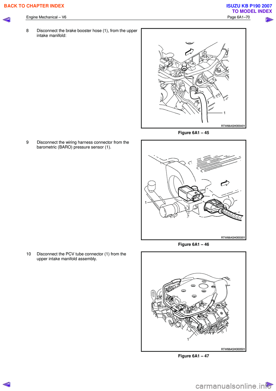
Engine Mechanical – V6 Page 6A1–70
8 Disconnect the brake booster hose (1), from the upper
intake manifold:
Figure 6A1 – 45
9 Disconnect the wiring harness connector from the barometric (BARO) pressure sensor (1).
Figure 6A1 – 46
10 Disconnect the PCV tube connector (1) from the upper intake manifold assembly.
Figure 6A1 – 47
BACK TO CHAPTER INDEX
TO MODEL INDEX
ISUZU KB P190 2007
Page 2551 of 6020
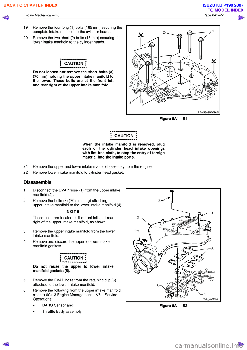
Engine Mechanical – V6 Page 6A1–72
19 Remove the four long (1) bolts (165 mm) securing the
complete intake manifold to the cylinder heads.
20 Remove the two short (2) bolts (45 mm) securing the lower intake manifold to the cylinder heads.
Do not loosen nor remove the short bolts ( �8
�8�8
�8
)
(70 mm) holding the upper intake manifold to
the lower. These bolts are at the front left
and rear right of the upper intake manifold.
Figure 6A1 – 51
When the intake manifold is removed, plug
each of the cylinder head intake openings
with lint free cloth, to stop the entry of foreign
material into the intake ports.
21 Remove the upper and lower intake manifold assembly from the engine.
22 Remove lower intake manifold to cylinder head gasket.
Disassemble
1 Disconnect the EVAP hose (1) from the upper intake manifold (2).
2 Remove the bolts (3) (70 mm long) attaching the upper intake manifold to the lower intake manifold (4).
NOTE
These bolts are located at the front left and rear
right of the upper intake manifold, as shown.
3 Remove the upper intake manifold from the lower intake manifold.
4 Remove and discard the upper to lower intake manifold gaskets.
Do not reuse the upper to lower intake
manifold gaskets (5).
5 Remove the EVAP hose from the retaining clip (6) attached to the lower intake manifold.
6 Remove the following from the upper intake manifold, refer to 6C1-3 Engine Management – V6 – Service
Operations:
• BARO Sensor and
• Throttle Body assembly
Figure 6A1 – 52
BACK TO CHAPTER INDEX
TO MODEL INDEX
ISUZU KB P190 2007