2007 ISUZU KB P190 display
[x] Cancel search: displayPage 1942 of 6020
ENGINE CONTROL SYSTEM (4JK1/4JJ1) 6E-325
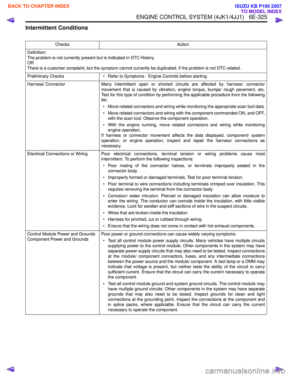
Intermittent Conditions
ChecksAction
Definition:
The problem is not currently present but is indicated in DTC History.
OR
There is a customer complaint, but the symptom cannot currently be duplicated, if the problem is not DTC related.
Preliminary Checks • Refer to Symptoms - Engine Controls before starting.
Harness/ Connector Many intermittent open or shorted circuits are affected by harness/ connector
movement that is caused by vibration, engine torque, bumps/ rough pavement, etc.
Test for this type of condition by performing the applicable procedure from the following
list:
• Move related connectors and wiring while monitoring the appropriate scan tool data.
• Move related connectors and wiring with the component commanded ON, and OFF, with the scan tool. Observe the component operation.
• With the engine running, move related connectors and wiring while monitoring engine operation.
If harness or connector movement affects the data displayed, component/ system
operation, or engine operation, inspect and repair the harness/ connections as
necessary.
Electrical Connections or Wiring Poor electrical connections, terminal tension or wiring problems cause most intermittent. To perform the following inspections:
• Poor mating of the connector halves, or terminals improperly seated in the connector body.
• Improperly formed or damaged terminals. Test for poor terminal tension.
• Poor terminal to wire connections including terminals crimped over insulation. This requires removing the terminal from the connector body.
• Corrosion/ water intrusion. Pierced or damaged insulation can allow moisture to enter the wiring. The conductor can corrode inside the insulation, with little visible
evidence. Look for swollen and stiff sections of wire in the suspect circuits.
• Wires that are broken inside the insulation.
• Harness for pinched, cut or rubbed through wiring.
• Ensure that the wiring does not come in contact with hot exhaust components.
Control Module Power and Grounds
Component Power and Grounds Poor power or ground connections can cause widely varying symptoms.
• Test all control module power supply circuits. Many vehicles have multiple circuits supplying power to the control module. Other components in the system may have
separate power supply circuits that may also need to be tested. Inspect connections
at the module/ component connectors, fuses, and any intermediate connections
between the power source and the module/ component. A test lamp or a DMM may
indicate that voltage is present, but neither tests the ability of the circuit to carry
sufficient current. Ensure that the circuit can carry the current necessary to operate
the component.
• Test all control module ground and system ground circuits. The control module may have multiple ground circuits. Other components in the system may have separate
grounds that may also need to be tested. Inspect grounds for clean and tight
connections at the grounding point. Inspect the connections at the component and
in splice packs, where applicable. Ensure that the circuit can carry the current
necessary to operate the component.
BACK TO CHAPTER INDEX
TO MODEL INDEX
ISUZU KB P190 2007
Page 1966 of 6020
ENGINE CONTROL SYSTEM (4JK1/4JJ1) 6E-349
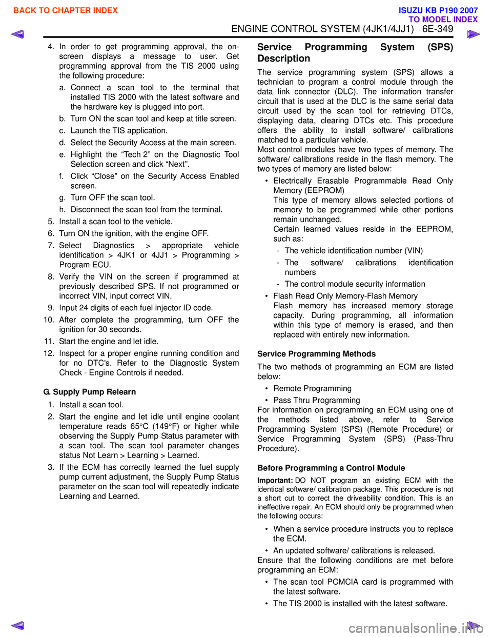
4. In order to get programming approval, the on-screen displays a message to user. Get
programming approval from the TIS 2000 using
the following procedure:
a. Connect a scan tool to the terminal that installed TIS 2000 with the latest software and
the hardware key is plugged into port.
b. Turn ON the scan tool and keep at title screen.
c. Launch the TIS application.
d. Select the Security Access at the main screen.
e. Highlight the “Tech 2” on the Diagnostic Tool Selection screen and click “Next”.
f. Click “Close” on the Security Access Enabled screen.
g. Turn OFF the scan tool.
h. Disconnect the scan tool from the terminal.
5. Install a scan tool to the vehicle.
6. Turn ON the ignition, with the engine OFF.
7. Select Diagnostics > appropriate vehicle identification > 4JK1 or 4JJ1 > Programming >
Program ECU.
8. Verify the VIN on the screen if programmed at previously described SPS. If not programmed or
incorrect VIN, input correct VIN.
9. Input 24 digits of each fuel injector ID code.
10. After complete the programming, turn OFF the ignition for 30 seconds.
11. Start the engine and let idle.
12. Inspect for a proper engine running condition and for no DTC's. Refer to the Diagnostic System
Check - Engine Controls if needed.
G. Supply Pump Relearn 1. Install a scan tool.
2. Start the engine and let idle until engine coolant temperature reads 65 °C (149 °F) or higher while
observing the Supply Pump Status parameter with
a scan tool. The scan tool parameter changes
status Not Learn > Learning > Learned.
3. If the ECM has correctly learned the fuel supply pump current adjustment, the Supply Pump Status
parameter on the scan tool will repeatedly indicate
Learning and Learned.Service Programming System (SPS)
Description
The service programming system (SPS) allows a
technician to program a control module through the
data link connector (DLC). The information transfer
circuit that is used at the DLC is the same serial data
circuit used by the scan tool for retrieving DTCs,
displaying data, clearing DTCs etc. This procedure
offers the ability to install software/ calibrations
matched to a particular vehicle.
Most control modules have two types of memory. The
software/ calibrations reside in the flash memory. The
two types of memory are listed below:
• Electrically Erasable Programmable Read Only Memory (EEPROM)
This type of memory allows selected portions of
memory to be programmed while other portions
remain unchanged.
Certain learned values reside in the EEPROM,
such as:
- The vehicle identification number (VIN)
- The software/ calibrations identification numbers
- The control module security information
• Flash Read Only Memory-Flash Memory Flash memory has increased memory storage
capacity. During programming, all information
within this type of memory is erased, and then
replaced with entirely new information.
Service Programming Methods
The two methods of programming an ECM are listed
below:
• Remote Programming
• Pass Thru Programming
For information on programming an ECM using one of
the methods listed above, refer to Service
Programming System (SPS) (Remote Procedure) or
Service Programming System (SPS) (Pass-Thru
Procedure).
Before Programming a Control Module
Important: DO NOT program an existing ECM with the
identical software/ calibration package. This procedure is not
a short cut to correct the driveability condition. This is an
ineffective repair. An ECM should only be programmed when
the following occurs:
• When a service procedure instructs you to replace the ECM.
• An updated software/ calibrations is released.
Ensure that the following conditions are met before
programming an ECM:
• The scan tool PCMCIA card is programmed with the latest software.
• The TIS 2000 is installed with the latest software.
BACK TO CHAPTER INDEX
TO MODEL INDEX
ISUZU KB P190 2007
Page 1967 of 6020
6E-350 ENGINE CONTROL SYSTEM (4JK1/4JJ1)
• The hardware key is plugged into the computerport.
• Vehicle system voltage: - There are no charging system concerns. Allcharging system concerns must be repaired
before programming the ECM.
- The battery voltage is greater than 12 volts but less than 16 volts. The battery must be fully
charged before programming the ECM.
- A battery charger is NOT connected to the vehicles battery. Incorrect system voltage or
voltage fluctuations from a battery charger may
cause programming failure or ECM damage.
- Turn OFF or disable any system that may put a load on the vehicles battery. Turn OFF or
disable systems such as:
◊ Heating, ventilation, and air conditioning
(HVAC) systems
◊ Headlights
◊ Room lights
◊ Accessory equipment
• The ignition switch is in the proper position. The scan tool prompts you to turn ON the ignition, with
the engine OFF. DO NOT change the position of
the ignition switch during the programming
procedure unless instructed to do so.
• All tool connections are secure: - The RS-232 cable
- The connection at the DLC
- The voltage supply circuits
• DO NOT disturb the tool harnesses while programming. If an interruption occurs during the
programming procedure, programming failure or
ECM damage may occur.
• If you are performing the Pass-Thru programming procedure using a notebook computer without the
power cord, ensure that the internal battery is fully
charged.
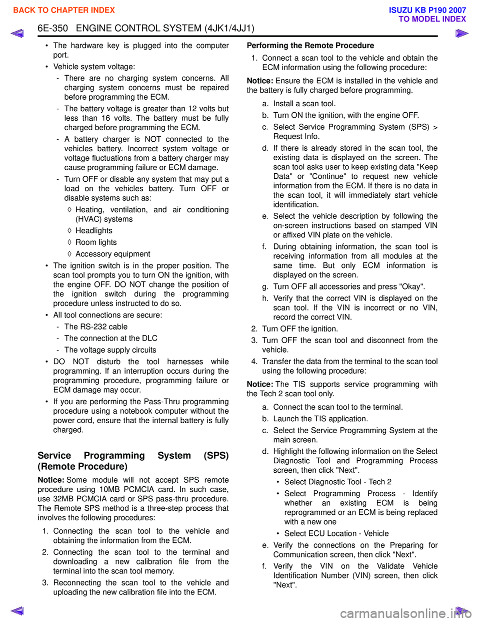
Service Programming System (SPS)
(Remote Procedure)
Notice: Some module will not accept SPS remote
procedure using 10MB PCMCIA card. In such case,
use 32MB PCMCIA card or SPS pass-thru procedure.
The Remote SPS method is a three-step process that
involves the following procedures:
1. Connecting the scan tool to the vehicle and obtaining the information from the ECM.
2. Connecting the scan tool to the terminal and downloading a new calibration file from the
terminal into the scan tool memory.
3. Reconnecting the scan tool to the vehicle and uploading the new calibration file into the ECM. Performing the Remote Procedure
1. Connect a scan tool to the vehicle and obtain the ECM information using the following procedure:
Notice: Ensure the ECM is installed in the vehicle and
the battery is fully charged before programming.
a. Install a scan tool.
b. Turn ON the ignition, with the engine OFF.
c. Select Service Programming System (SPS) > Request Info.
d. If there is already stored in the scan tool, the existing data is displayed on the screen. The
scan tool asks user to keep existing data "Keep
Data" or "Continue" to request new vehicle
information from the ECM. If there is no data in
the scan tool, it will immediately start vehicle
identification.
e. Select the vehicle description by following the on-screen instructions based on stamped VIN
or affixed VIN plate on the vehicle.
f. During obtaining information, the scan tool is receiving information from all modules at the
same time. But only ECM information is
displayed on the screen.
g. Turn OFF all accessories and press "Okay".
h. Verify that the correct VIN is displayed on the scan tool. If the VIN is incorrect or no VIN,
record the correct VIN.
2. Turn OFF the ignition.
3. Turn OFF the scan tool and disconnect from the vehicle.
4. Transfer the data from the terminal to the scan tool using the following procedure:
Notice: The TIS supports service programming with
the Tech 2 scan tool only.
a. Connect the scan tool to the terminal.
b. Launch the TIS application.
c. Select the Service Programming System at the main screen.
d. Highlight the following information on the Select Diagnostic Tool and Programming Process
screen, then click "Next".
• Select Diagnostic Tool - Tech 2
• Select Programming Process - Identify whether an existing ECM is being
reprogrammed or an ECM is being replaced
with a new one
• Select ECU Location - Vehicle
e. Verify the connections on the Preparing for Communication screen, then click "Next".
f. Verify the VIN on the Validate Vehicle Identification Number (VIN) screen, then click
"Next".
BACK TO CHAPTER INDEX
TO MODEL INDEX
ISUZU KB P190 2007
Page 1968 of 6020
ENGINE CONTROL SYSTEM (4JK1/4JJ1) 6E-351
Notice:If the ECM is replaced to new one, VIN does
not displayed. Input correct VIN reading from stamped
VIN or affixed VIN plate on the vehicle. If the ECM from
another vehicle is installed, input correct VIN by same
way.
g. Highlight Engine on the Select System Typescreen, then click "Next", if on-screen
instruction displayed.
h. Complete the following information based on the service ID plate on the Validate Vehicle
Data screen until "Next" is highlighted, then
click "Next".
• Model
• Model year
• Engine type
• Model designator
• Destination code
• Transmission type
i. Verify your selection on the Summary screen.
Notice: Refer to Service Bulletin and Description
column before service programming is performed if the
bulletins are listed along with the calibration files.
Notice: Select Cancel if you receive a message stating
that the calibration selected is already the current
calibration in the ECM and reprogramming with the
same download is not allowed.
j. Click "Reprog".
k. The Transfer Data screen will appear until the progress bar reaches 100%.
5. Close the application and return to the TIS application selection screen after the download is
completed.
6. Turn OFF the scan tool and disconnect from the terminal.
7. Transfer the data from the scan tool to the ECM using the following procedure:
a. Install a scan tool.
b. Turn ON the ignition, with the engine OFF.
c. Select Service Programming System (SPS) > Program ECU.
d. Turn OFF all accessories and press "Continue".
e. Programming in Process will appear until the progress bar reaches 100%.
Notice: Some warning lamp may turn ON or blink while
programming the ECM since communication between
the ECM and other modules are interrupted. Clear DTC
in any module after programming.
f. Press "Continue" and exit the program after thescan tool displays "Programming Was
Successful".
8. Turn OFF the ignition.
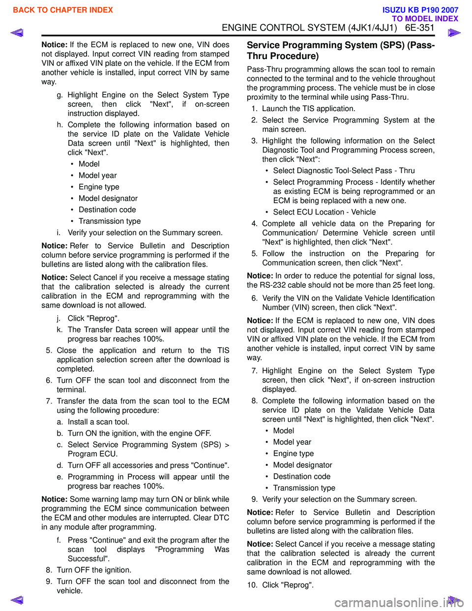
9. Turn OFF the scan tool and disconnect from the vehicle.Service Programming System (SPS) (Pass-
Thru Procedure)
Pass-Thru programming allows the scan tool to remain
connected to the terminal and to the vehicle throughout
the programming process. The vehicle must be in close
proximity to the terminal while using Pass-Thru.
1. Launch the TIS application.
2. Select the Service Programming System at the main screen.
3. Highlight the following information on the Select Diagnostic Tool and Programming Process screen,
then click "Next":
• Select Diagnostic Tool-Select Pass - Thru
• Select Programming Process - Identify whether as existing ECM is being reprogrammed or an
ECM is being replaced with a new one.
• Select ECU Location - Vehicle
4. Complete all vehicle data on the Preparing for Communication/ Determine Vehicle screen until
"Next" is highlighted, then click "Next".
5. Follow the instruction on the Preparing for Communication screen, then click "Next".
Notice: In order to reduce the potential for signal loss,
the RS-232 cable should not be more than 25 feet long.
6. Verify the VIN on the Validate Vehicle Identification Number (VIN) screen, then click "Next".
Notice: If the ECM is replaced to new one, VIN does
not displayed. Input correct VIN reading from stamped
VIN or affixed VIN plate on the vehicle. If the ECM from
another vehicle is installed, input correct VIN by same
way.
7. Highlight Engine on the Select System Type screen, then click "Next", if on-screen instruction
displayed.
8. Complete the following information based on the service ID plate on the Validate Vehicle Data
screen until "Next" is highlighted, then click "Next".
• Model
• Model year
• Engine type
• Model designator
• Destination code
• Transmission type
9. Verify your selection on the Summary screen.
Notice: Refer to Service Bulletin and Description
column before service programming is performed if the
bulletins are listed along with the calibration files.
Notice: Select Cancel if you receive a message stating
that the calibration selected is already the current
calibration in the ECM and reprogramming with the
same download is not allowed.
10. Click "Reprog".
BACK TO CHAPTER INDEX
TO MODEL INDEX
ISUZU KB P190 2007
Page 1972 of 6020
ENGINE CONTROL SYSTEM (4JK1/4JJ1) 6E-355
Electrostatic Discharge Damage
Electronic components used in the ECM are often
designed to carry very low voltage. Electronic
components are susceptible to damage caused by
electrostatic discharge. By comparison, as much as
4,000 volts may be needed for a person to feel even
the zap of a static discharge. There are several ways
for a person to become statically charged. The most
common methods of charging are by friction and
induction.
• An example of charging by friction is a person sliding across a vehicle seat.
Important: To prevent possible electrostatic discharge
damage, follow these guidelines:
• Do not touch the ECM connector pins or soldered components on the ECM circuit board.
• Do not open the replacement part package until the part is ready to be installed.
• Before removing the part from the package, ground the package to a known good ground on
the vehicle.
• If the part has been handled while sliding across the seat, while sitting down from a standing
position, or while walking a distance, touch a
known good ground before installing the part.
• Charge by induction occurs when a person with well insulated shoes stands near a highly charged
object and momentarily touches ground. Charges
of the same polarity are drained off leaving the
person highly charged with opposite polarity.
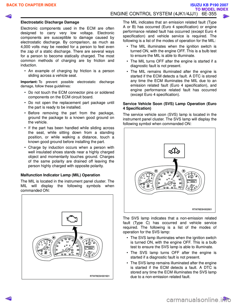
Malfunction Indicator Lamp (MIL) Operation
The MIL is located in the instrument panel cluster. The
MIL will display the following symbols when
commanded ON: The MIL indicates that an emission related fault (Type
A or B) has occurred (Euro 4 specification) or engine
performance related fault has occurred (except Euro 4
specification) and vehicle service is required. The
following is a list of the modes of operation for the MIL:
• The MIL illuminates when the ignition switch is turned ON, with the engine OFF. This is a bulb test
to ensure the MIL is able to illuminate.
• The MIL turns OFF after the engine is started if a diagnostic fault is not present.
• The MIL remains illuminated after the engine is started if the ECM detects a fault. A DTC is stored
any time the ECM illuminates the MIL due to an
emission related fault (Euro 4 specification), and
engine performance related fault has occurred
(except Euro 4 specification).
Service Vehicle Soon (SVS) Lamp Operation (Euro
4 Specification)
The service vehicle soon (SVS) lamp is located in the
instrument panel cluster. The SVS lamp will display the
following symbol when commanded ON:
The SVS lamp indicates that a non-emission related
fault (Type C) has occurred and vehicle service
required. The following is a list of the modes of
operation for the SVS lamp:
• The SVS lamp illuminates when the ignition switch is turned ON, with the engine OFF. This is a bulb
test to ensure the SVS lamp is able to illuminate.
• The SVS lamp turns OFF after the engine is started if a diagnostic fault is not present.
• The SVS lamp remains illuminated after the engine is started if the ECM detects a fault. A DTC is
stored any time the ECM illuminates the SVS lamp
due to a non-emission related fault.
RTW76ESH001901
RTW76ESH002901
BACK TO CHAPTER INDEX
TO MODEL INDEX
ISUZU KB P190 2007
Page 1977 of 6020
6E-360 ENGINE CONTROL SYSTEM (4JK1/4JJ1)
1. High Pressure Control• Enables high pressure injection from low engine speed range.
• Optimizes control to minimize particulate matter and NOx emissions.
2. Injection Timing Control
• Enables finely tuned optimized control in accordance with running conditions.
3. Injection Rate Control
• Pilot injection control that performs a small amount of injection before main injection.
The fuel rail system consists primarily of a fuel supply
pump, fuel rail, injectors, and ECM.
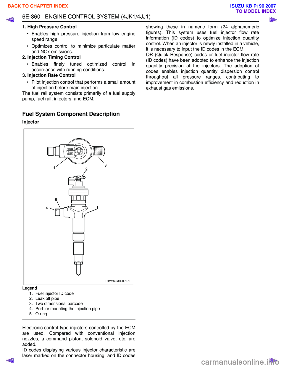
Fuel System Component Description
Injector
Legend
1. Fuel injector ID code
2. Leak off pipe
3. Two dimensional barcode
4. Port for mounting the injection pipe
5. O-ring
Electronic control type injectors controlled by the ECM
are used. Compared with conventional injection
nozzles, a command piston, solenoid valve, etc. are
added.
ID codes displaying various injector characteristic are
laser marked on the connector housing, and ID codes showing these in numeric form (24 alphanumeric
figures). This system uses fuel injector flow rate
information (ID codes) to optimize injection quantity
control. When an injector is newly installed in a vehicle,
it is necessary to input the ID codes in the ECM.
QR (Quick Response) codes or fuel injector flow rate
(ID codes) have been adopted to enhance the injection
quantity precision of the injectors. The adoption of
codes enables injection quantity dispersion control
throughout all pressure ranges, contributing to
improvement in combustion efficiency and reduction in
exhaust gas emissions.
RTW56EMH000101
23
1
4
5
BACK TO CHAPTER INDEX
TO MODEL INDEX
ISUZU KB P190 2007
Page 2172 of 6020
6E–2 ENGINE DRIVEABILITY AND EMISSIONS
5e. Vehicle Operates as Designed ............ 6E-65
6. Re-examine the complaint ..................... 6E-66
7. Repair and Verify Fix ............................. 6E-66
GENERAL SERVICE INFORMATION .......... 6E-67 On-Board Diagnostic (OBD) ...................... 6E-68
On-Board Diagnostic Tests ....................... 6E-68
The Diagnostic Executive .......................... 6E-68
Diagnostic Information ............................... 6E-68
Check Engine Lamp .................................. 6E-68
Data Link Connector (DLC) ....................... 6E-68
Tech 2 Operating Flow Cart (Start Up) ...... 6E-70
TYPICAL SCAN DATA & DEFINITIONS (ENGINE DATA) ......................................... 6E-72
TYPICAL SCAN DATA & DEFINITIONS (O2 SENSOR DATA) .................................. 6E-74
MISCELLANEOUS TEST ............................. 6E-76
PLOTTING SNAPSHOT GRAPH ................. 6E-78 Plotting Graph Flow Chart (Plotting graph after obtaining vehicle information) .................. 6E-79
Flow Chart for Snapshot Replay (Plotting Graph) ....................................... 6E-80
SNAPSHOT DISPLAY WITH TIS2000 ......... 6E-81
ON-BOARD DIAGNOSTIC (OBD) SYSTEM CHECK 6E-98
Circuit Description ......................................... 6E-90
Diagnostic Aids ............................................. 6E-90
Test Description ............................................ 6E-90
ON-BOARD DIAGNOSTIC (OBD) SYSTEM CHECK .................................................... 6E-91
NO CHECK ENGINE LAMP (MIL) ................ 6E-94 Circuit Description ..................................... 6E-94
Diagnostic Aids .......................................... 6E-94
No Check Engine Lamp (MIL) ................... 6E-94
CHECK ENGINE LAMP (MIL) “ON” STEADY 6E-96 Circuit description ...................................... 6E-96
Diagnostic Aids .......................................... 6E-96
Check Engine Lamp (MIL) “ON” Steady .... 6E-96
FUEL METERING SYSTEM CHECK ........... 6E-98
FUEL INJECTOR COIL TEST PROCEDURE AND FUEL INJECTOR BALANCE TEST
PROCEDURE ............................................. 6E-98
Test Description ......................................... 6E-98
Injector Coil Test Procedure (Steps 1-6) and Injector Balance Test Procedure
(Steps 7-11) ............................................. 6E-99
Injector Coil Test Procedure (Steps 1-6) and Injector Balance Test Procedure
(Steps 7-11) ............................................. 6E-100
FUEL SYSTEM ELECTRICAL TEST ........... 6E-103 Circuit Description ..................................... 6E-103
Diagnostic Aids .......................................... 6E-104 Fuel Pressure Relief Procedure ................. 6E-104
Fuel Pressure Gauge Installation .............. 6E-104
Fuel System Electrical Test ....................... 6E-104
FUEL SYSTEM DIAGNOSIS ........................ 6E-108 Circuit Description ...................................... 6E-108
Test Description ......................................... 6E-108
Fuel Pressure Relief Procedure ................. 6E-109
Fuel Pressure Gauge Installation .............. 6E-109
Fuel System Diagnosis .............................. 6E-110
ECM DIAGNOSTIC TROUBLE CODES (DTC) 6E-113
DIAGNOSTIC TROUBLE CODE (DTC) P0107 MANIFOLD ABSOLUTE PRESSURE
CIRCUIT LOW INPUT ................................ 6E-119
Circuit Description ...................................... 6E-119
Diagnostic Aids .......................................... 6E-119
Diagnostic Trouble Code (DTC) P0107 Manifold Absolute Pressure Circuit Low
Input ......................................................... 6E-120
DIAGNOSTIC TROUBLE CODE (DTC) P0108 MANIFOLD ABSOLUTE PRESSURE
CIRCUIT HIGH INPUT ............................... 6E-123
Circuit Description ...................................... 6E-123
Diagnostic Aids .......................................... 6E-124
Diagnostic Trouble Code (DTC) P0108 Manifold Absolute Pressure Circuit High
Input ......................................................... 6E-124
DIAGNOSTIC TROUBLE CODE (DTC) P0112 INTAKE AIR TEMPERATURE SENSOR LOW
INPUT ......................................................... 6E-127
Circuit Description ...................................... 6E-127
Diagnostic Aids .......................................... 6E-127
Diagnostic Trouble Code (DTC) P0112 Intake Air Temperature Sensor Low Input 6E-128
DIAGNOSTIC TROUBLE CODE (DTC) P0113 INTAKE AIR TEMPERATURE SENSOR HIGH
INPUT ......................................................... 6E-131
Circuit Description ...................................... 6E-131
Diagnostic Aids .......................................... 6E-131
Diagnostic Trouble Code (DTC) P0113 Intake Air Temperature Sensor High Input 6E-132
DIAGNOSTIC TROUBLE CODE (DTC) P0117 ENGINE COOLANT TEMPERATURE
SENSOR LOW INPUT ................................ 6E-136
Circuit Description ...................................... 6E-136
Diagnostic Aids .......................................... 6E-136
Diagnostic Trouble Code (DTC) P0117 Engine Coolant Temperature Sensor Low
Input ......................................................... 6E-137
DIAGNOSTIC TROUBLE CODE (DTC) P0118 ENGINE COOLANT TEMPERATURE
SENSOR HIGH INPUT ............................... 6E-139
Circuit Description ...................................... 6E-139
BACK TO CHAPTER INDEX
TO MODEL INDEX
ISUZU KB P190 2007
Page 2238 of 6020
6E–68 ENGINE DRIVEABILITY AND EMISSIONS
On-Board Diagnostic (OBD)
On-Board Diagnostic Tests
A diagnostic test is a series of steps, the result of which
is a pass or fail reported to the diagnostic executive.
When a diagnostic test reports a pass result, the
diagnostic executive records the following data:
• The diagnostic test has been completed since the last ignition cycle.
• The diagnostic test has passed during the current ignition cycle.
• The fault identified by the diagnostic test is not currently active.
When a diagnostic test reports a fail result, the
diagnostic executive records the following data:
• The diagnostic test has been completed since the last ignition cycle.
• The fault identified by the diagnostic test is currently active.
• The fault has been active during this ignition cycle.
• The operating conditions at the time of the failure.
The Diagnostic Executive
The Diagnostic Executive is a unique segment of
software which is designed to coordinate and prioritize
the diagnostic procedures as well as define the protocol
for recording and displaying their results. The main
responsibilities of the Diagnostic Executive are listed as
follows:
• Commanding the check engine lamp on and off
• DTC logging and clearing
• Current status information on each diagnostic
Diagnostic Information
The diagnostic charts and functional checks are
designed to locate a faulty circuit or component through
a process of logical decisions. The charts are prepared
with the requirement that the vehicle functioned
correctly at the time of assembly and that there are not
multiple faults present.
There is a continuous self-diagnosis on certain control
functions. This diagnostic capability is complemented
by the diagnostic procedures contained in this manual.
The language of communicating the source of the
malfunction is a system of diagnostic trouble codes.
When a malfunction is detected by the control module, a
diagnostic trouble code is set and the check engine
lamp is illuminated.
Check Engine Lamp
The check engine lamp looks the same as the check
engine lamp you are already familiar with, the “Check
Engine” lamp.
Basically, the check engine lamp is turned on when the
ECM detects a DTC that will impact the vehicle
emissions.
• When the check engine lamp remains “ON” while the engine is running, or when a malfunction is suspected due to a driveability or emissions problem,
a Powertrain On-Board Diagnostic (OBD) System
Check must be performed. The procedures for these
checks are given in On-Board Diagnostic (OBD)
System Check. These checks will expose faults
which may not be detected if other diagnostics are
performed first.
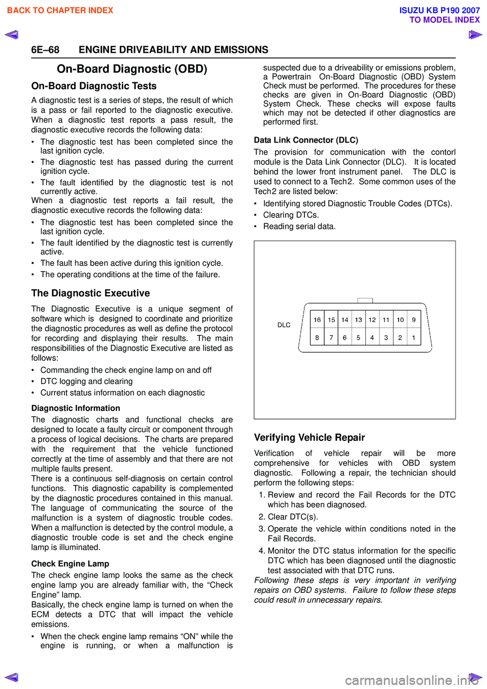
Data Link Connector (DLC)
The provision for communication with the contorl
module is the Data Link Connector (DLC). It is located
behind the lower front instrument panel. The DLC is
used to connect to a Tech 2. Some common uses of the
Tech 2 are listed below:
• Identifying stored Diagnostic Trouble Codes (DTCs).
• Clearing DTCs.
• Reading serial data.
Verifying Vehicle Repair
Verification of vehicle repair will be more
comprehensive for vehicles with OBD system
diagnostic. Following a repair, the technician should
perform the following steps:
1. Review and record the Fail Records for the DTC which has been diagnosed.
2. Clear DTC(s).
3. Operate the vehicle within conditions noted in the Fail Records.
4. Monitor the DTC status information for the specific DTC which has been diagnosed until the diagnostic
test associated with that DTC runs.
Following these steps is very important in verifying
repairs on OBD systems. Failure to follow these steps
could result in unnecessary repairs.
BACK TO CHAPTER INDEX
TO MODEL INDEX
ISUZU KB P190 2007