2007 ISUZU KB P190 battery
[x] Cancel search: batteryPage 3960 of 6020
Automatic Transmission – 4L60E – On-vehicle Servicing Page 7C4–47
14 Reconnect the fuel and EVAP pipes three brackets and clips, refer to 6C Fuel System – V6.
15 Reinstall the following components:
a Starter motor, refer to 6D1-2 Starting System.
b Transmission support, refer to 3.7 Transmission Support and Mount.
c Front and centre exhaust assemblies, refer to 6F Exhaust System.
d Rear propeller shaft and for 4WD front propeller shaft, refer to 4A Propeller Shaft.
16 Reconnect the harness connectors to the following: a Vehicle speed sensor, refer to 3.5 Vehicle Speed Sensor.
b Neutral start and back-up switch, refer to 3.4 Neutral Start and Back-up Lamp Switch.
c For the following on 4W D vehicles, refer to 7D Transfer Case and Adaptor Housing:
• neutral switch,
• 2WD – 4WD shift actuator switch,
• speed sensor.
17 Reinstall the selector cable to the transmission external manual shaft linkage, secure the selector cable to the bracket and attach the heat shield to the neutral start and back-up lamp switch, refer to 3.3 Selector Cable
Assembly.
18 Perform a reverse flush of the cooler lines and a flow rate test, refer to 2.2 Reverse Flush and Flow Rate, if either of the following applies:
• the transmission fluid is contaminated,
• the transmission has been replaced,
• the torque converter has been replaced, or
• the transmission oil pump has been replaced.
19 Lower the vehicle to the ground.
20 If required, top up the transmission fluid level (cold).
21 Reconnect the battery ground lead.
22 Start the engine and check for any fluid leaking at the fittings. If a leak is found, stop the engine and rectify the leak.
23 Road test until the transmission has reached operating temperature. Re-check the fluid level and for any fluid leaks, refer to 2.1 Transmission Fluid.
3.19 Transmission Control Module
Remove
1 Ensure the ignition switch is in the OFF position.
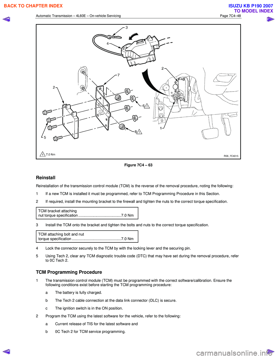
2 Disconnect the connector (1) from the transmission control module (TCM) (2) as follows, refer to Figure 7C4 – 63: a remove the securing pin (3),
b press the locking tab and swing the lever (4) to free the connector,
c remove the connector.
3 Remove the four bolts (5) and nuts (6), then the TCM from the mounting bracket (7).
4 If required, remove the two nuts (8) and the mounting bracket from the firewall.
BACK TO CHAPTER INDEX
TO MODEL INDEX
ISUZU KB P190 2007
Page 3961 of 6020
Automatic Transmission – 4L60E – On-vehicle Servicing Page 7C4–48
Figure 7C4 – 63
Reinstall
Reinstallation of the transmission control module (TCM) is the reverse of the removal procedure, noting the following:
1 If a new TCM is installed it must be programmed, refer to TCM Programming Procedure in this Section.
2 If required, install the mounting bracket to the firewall and tighten the nuts to the correct torque specification.
TCM bracket attaching
nut torque specification ........................................7.0 Nm
3 Install the TCM onto the bracket and tighten the bolts and nuts to the correct torque specification. TCM attaching bolt and nut
torque specification ..............................................7.0 Nm
4 Lock the connector securely to the TCM by with the locking lever and the securing pin.
5 Using Tech 2, clear any TCM diagnostic trouble code (DTC) that may have set during the removal procedure, refer to 0C Tech 2.
TCM Programming Procedure
1 The transmission control module (TCM) must be programmed with the correct software/calibration. Ensure the following conditions exist before starting the TCM programming procedure:
a The battery is fully charged.
b The Tech 2 cable connection at the data link connector (DLC) is secure.
c The ignition switch is in the ON position.
2 Program the TCM using the latest software for the vehicle, refer to the following: a Current release of TIS for the latest software and
b 0C Tech 2 for TCM service programming.
BACK TO CHAPTER INDEX
TO MODEL INDEX
ISUZU KB P190 2007
Page 3974 of 6020
7A2-8 TRANSMISSION CONTROL SYSTEM (AW30–40LE)
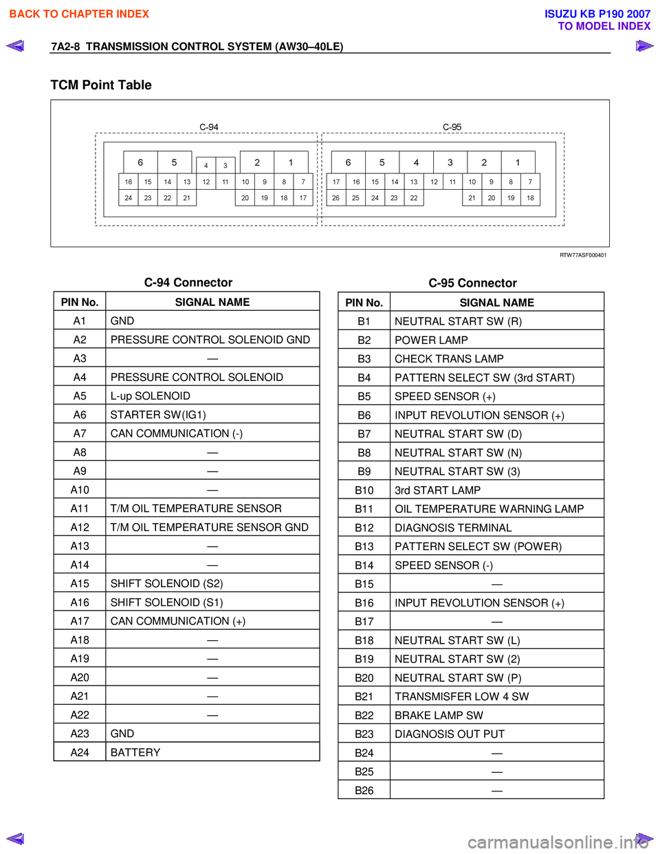
TCM Point Table
RTW 77ASF000401
C-94 Connector
PIN No. SIGNAL NAME
A1 GND
A2 PRESSURE CONTROL SOLENOID GND
A3 —
A4 PRESSURE CONTROL SOLENOID
A5 L-up SOLENOID
A6 STARTER SW (IG1)
A7 CAN COMMUNICATION (-)
A8 —
A9 —
A10 —
A11 T/M OIL TEMPERATURE SENSOR
A12 T/M OIL TEMPERATURE SENSOR GND
A13 —
A14 —
A15 SHIFT SOLENOID (S2)
A16 SHIFT SOLENOID (S1)
A17 CAN COMMUNICATION (+)
A18 —
A19 —
A20 —
A21 —
A22 —
A23 GND
A24 BATTERY
C-95 Connector
PIN No. SIGNAL NAME
B1 NEUTRAL START SW (R)
B2 POW ER LAMP
B3 CHECK TRANS LAMP
B4 PATTERN SELECT SW (3rd START)
B5 SPEED SENSOR (+)
B6 INPUT REVOLUTION SENSOR (+)
B7 NEUTRAL START SW (D)
B8 NEUTRAL START SW (N)
B9 NEUTRAL START SW (3)
B10 3rd START LAMP
B11 OIL TEMPERATURE W ARNING LAMP
B12 DIAGNOSIS TERMINAL
B13 PATTERN SELECT SW (POW ER)
B14 SPEED SENSOR (-)
B15 —
B16 INPUT REVOLUTION SENSOR (+)
B17 —
B18 NEUTRAL START SW (L)
B19 NEUTRAL START SW (2)
B20 NEUTRAL START SW (P)
B21 TRANSMISFER LOW 4 SW
B22 BRAKE LAMP SW
B23 DIAGNOSIS OUT PUT
B24 —
B25 —
B26 —
BACK TO CHAPTER INDEX
TO MODEL INDEX
ISUZU KB P190 2007
Page 3984 of 6020
7A2-18 TRANSMISSION CONTROL SYSTEM (AW30–40LE)
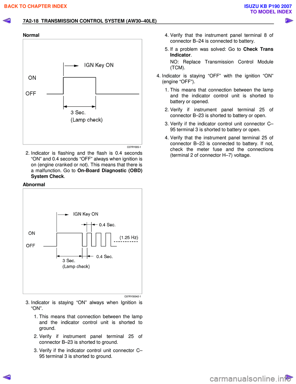
Normal
C07RY005-1
2. Indicator is flashing and the flash is 0.4 seconds
“ON” and 0.4 seconds “OFF” always when ignition is
on (engine cranked or not). This means that there is
a malfunction. Go to On-Board Diagnostic (OBD)
System Check .
Abnormal
C07RY00042-1
3. Indicator is staying “ON” always when Ignition is
“ON”.
1. This means that connection between the lamp
and the indicator control unit is shorted to
ground.
2. Verify if instrument panel terminal 25 o
f
connector B–23 is shorted to ground.
3. Verify if the indicator control unit connector C–
95 terminal 3 is shorted to ground.
4. Verify that the instrument panel terminal 8 o
f
connector B–24 is connected to battery.
5. If a problem was solved: Go to Check Trans
Indicator .
NO: Replace Transmission Control Module
(TCM).
4. Indicator is staying “OFF” with the ignition “ON”
(engine “OFF”).
1. This means that connection between the lamp
and the indicator control unit is shorted to
battery or opened.
2. Verify if instrument panel terminal 25 o
f
connector B–23 is shorted to battery or open.
3. Verify if the indicator control unit connector C–
95 terminal 3 is shorted to battery or open.
4. Verify that the instrument panel terminal 25 o
f
connector B–23 is connected to battery. If not,
check the meter fuse and the connections
(terminal 2 of connector H–7) voltage.
BACK TO CHAPTER INDEX
TO MODEL INDEX
ISUZU KB P190 2007
Page 3996 of 6020
7A2-30 TRANSMISSION CONTROL SYSTEM (AW30–40LE)
Service Programming System (SPS)
The procedure to program the control unit by using the
Service Programming System (SPS) software
contained in TIS2000 is explained below.
NOTE: • Should Tech2 display “SPS Procedure was not
successful”, engine will not start, but no DTCs are
present, low battery voltage or poor electrical
connections should be the primary suspects.
Perform the SPS procedure again after rectifying
the fault/s.
IMPORTANT:
Perform the following checks before attempting to
program the control unit:
•
••
•
The Tech2 PCMCIA card is programmed with
the latest software release.
•
••
•
The latest release of TIS2000 is loaded on the
PC.
•
••
•
The vehicle battery is fully charged.
•
••
•
The control unit to be programmed is
connected to the vehicle.
1. Preparations of TIS 2000
1. Connect Tech 2 to P/C.
2. Check to see if Hardware Key is plugged into Port.
3. Activate TIS 2000 by P/C.
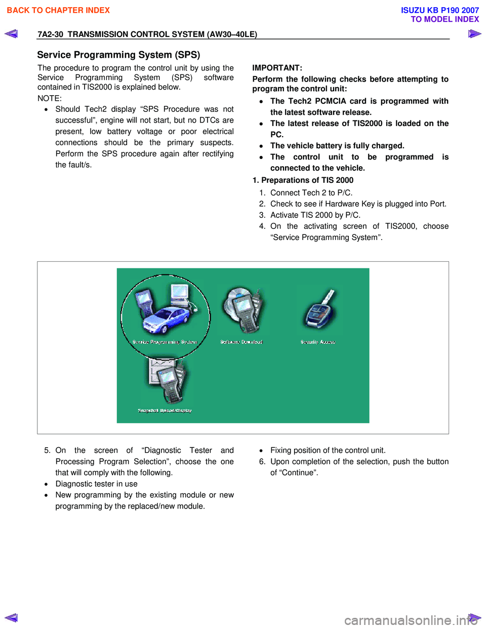
4. On the activating screen of TIS2000, choose
“Service Programming System”.
5. On the screen of “Diagnostic Tester and
Processing Program Selection”, choose the one
that will comply with the following.
• Diagnostic tester in use
• New programming by the existing module or ne
w
programming by the replaced/new module.
• Fixing position of the control unit.
6. Upon completion of the selection, push the button
of “Continue”.
BACK TO CHAPTER INDEX
TO MODEL INDEX
ISUZU KB P190 2007
Page 4000 of 6020
7A2-34 TRANSMISSION CONTROL SYSTEM (AW30–40LE)
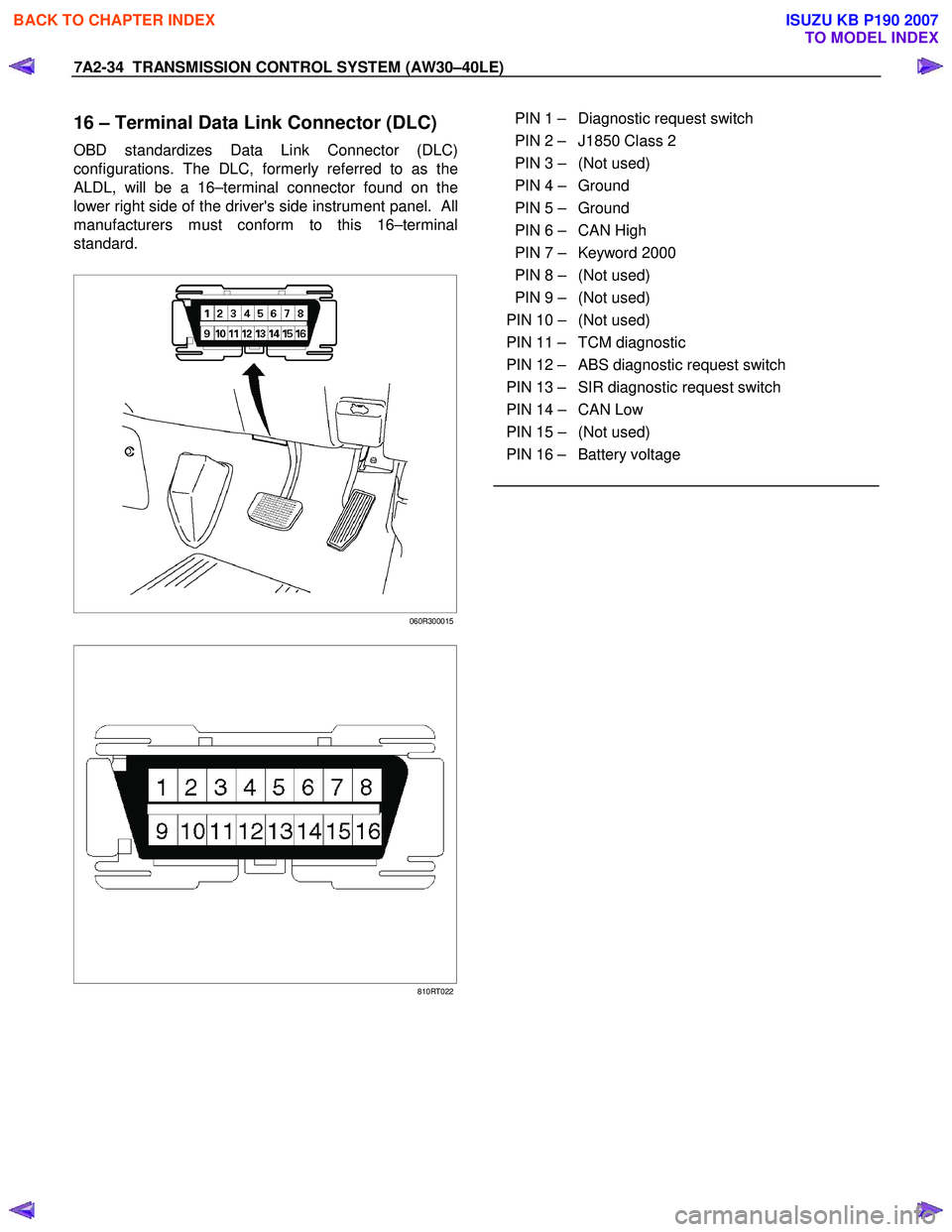
16 – Terminal Data Link Connector (DLC)
OBD standardizes Data Link Connector (DLC)
configurations. The DLC, formerly referred to as the
ALDL, will be a 16–terminal connector found on the
lower right side of the driver's side instrument panel. All
manufacturers must conform to this 16–terminal
standard.
060R300015
810RT022
PIN 1 – Diagnostic request switch
PIN 2 – J1850 Class 2
PIN 3 – (Not used)
PIN 4 – Ground
PIN 5 – Ground
PIN 6 – CAN High
PIN 7 – Keyword 2000
PIN 8 – (Not used)
PIN 9 – (Not used)
PIN 10 – (Not used)
PIN 11 – TCM diagnostic
PIN 12 – ABS diagnostic request switch
PIN 13 – SIR diagnostic request switch
PIN 14 – CAN Low
PIN 15 – (Not used)
PIN 16 – Battery voltage
BACK TO CHAPTER INDEX
TO MODEL INDEX
ISUZU KB P190 2007
Page 4007 of 6020
TRANSMISSION CONTROL SYSTEM (AW30–40LE) 7A2-41
• All of the following conditions are met.
- Device Control is not operating
- Disable Normal Communication Service is receiving enable
- DTC Clear is not operating
Condition For Setting The DTC
W hen the TCM detects following conditions at 20 times
continuously.
• Ignition voltage is less than 9 volts for 1 second o
r
more continuously. (DTC P0562)
• Ignition voltage is more than 18 volts for 1 second o
r
more continuously. (DTC P0563)
Action Taken When The DTC Sets
• DTC stored.
Conditions For Clearing The DTC
• The DTC can be cleared from the TCM history by
using a scan tool.
• The DTC will be cleared from history when the
vehicle has achieved 40 warm-up cycles without a
failure reported.
•
After more than 1 second has elapsed after the
ignition key has been turned “ON”, short between
No.11 and No.4 (ground) of DLC (Data Link
Connector). Then, after 1 second, but within 6
seconds, discontinue shorting.
Diagnostic Aids
•
Inspect the wiring for poor electrical connection at the
TCM. Look for possible bent, backed out, deformed
or damaged terminals. Check for weak terminal
tension as well. Also check for a chafed wire that
could short to bare metal or other wiring.
Inspect for a broken wire inside the insulation.
• W hen diagnosing for a possible intermittent short o
r
open condition, move the wiring harness while
observing test equipment for a change.
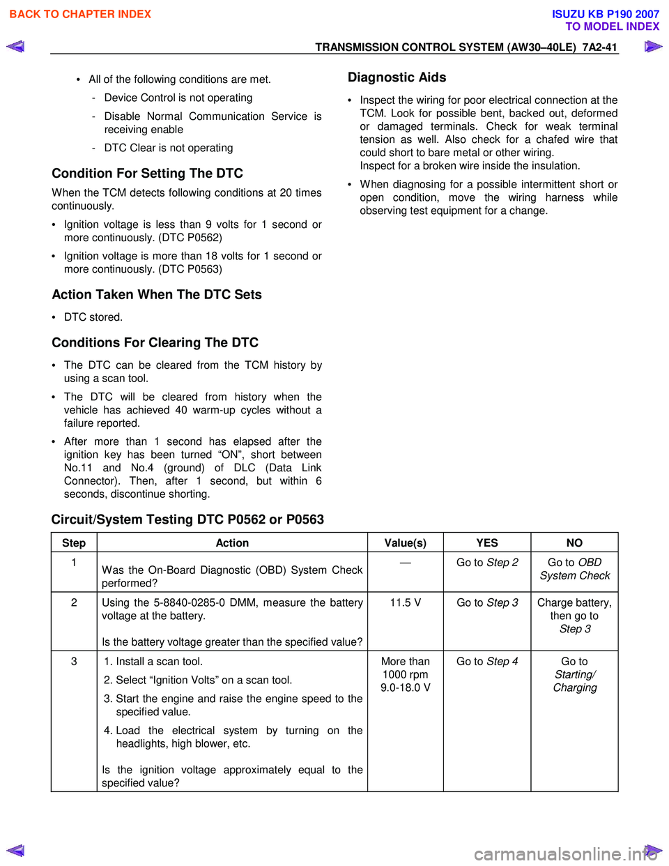
Circuit/System Testing DTC P0562 or P0563
Step Action Value(s) YES NO
1
W as the On-Board Diagnostic (OBD) System Check
performed? — Go to
Step 2 Go to OBD
System Check
2 Using the 5-8840-0285-0 DMM, measure the battery voltage at the battery.
Is the battery voltage greater than the specified value? 11.5 V Go to
Step 3 Charge battery,
then go to Step 3
3 1. Install a scan tool.
2. Select “Ignition Volts” on a scan tool.
3. Start the engine and raise the engine speed to the specified value.
4. Load the electrical system by turning on the headlights, high blower, etc.
Is the ignition voltage approximately equal to the
specified value? More than
1000 rpm
9.0-18.0 V Go to
Step 4 Go to
Starting/
Charging
BACK TO CHAPTER INDEX
TO MODEL INDEX
ISUZU KB P190 2007
Page 4008 of 6020
7A2-42 TRANSMISSION CONTROL SYSTEM (AW30–40LE)
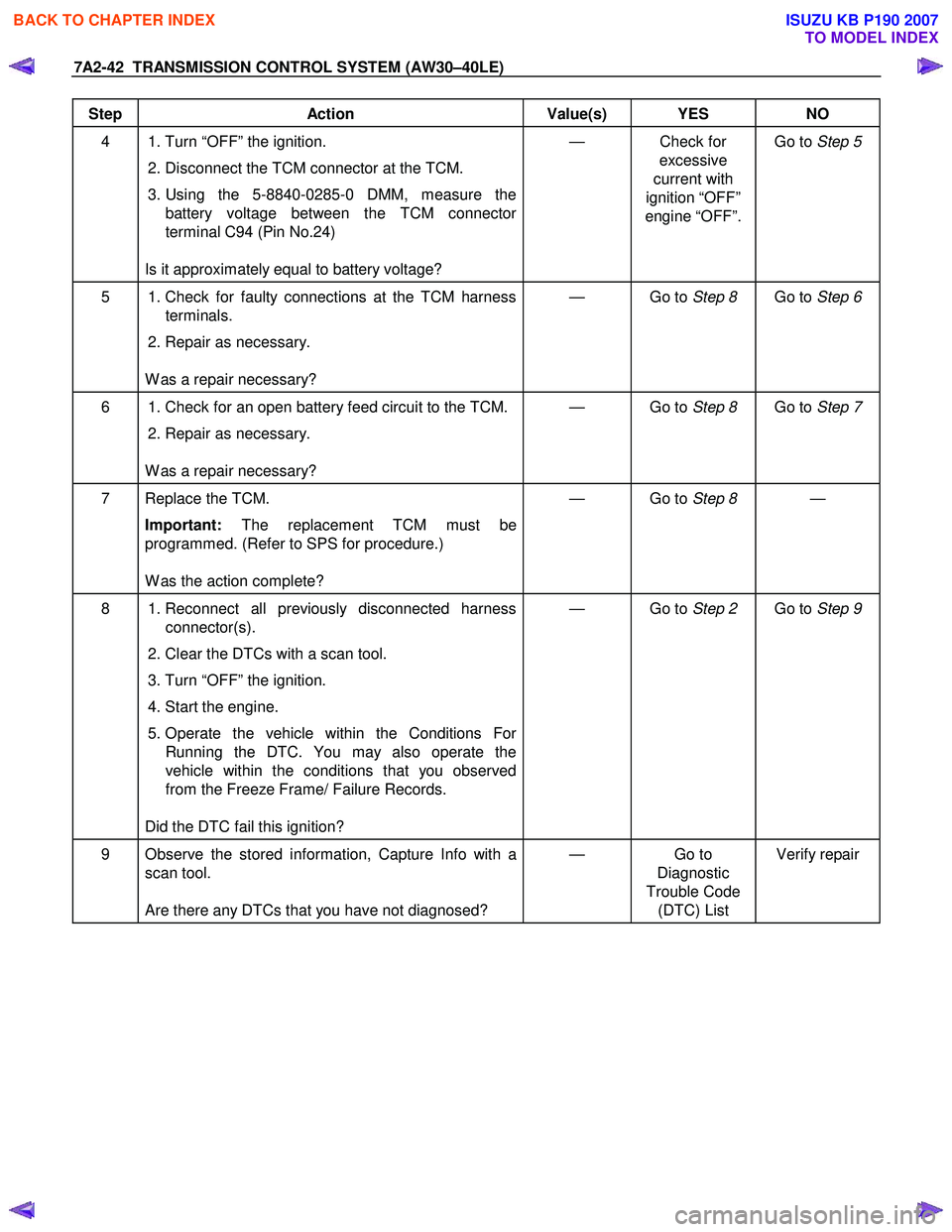
Step Action Value(s) YES NO
4 1. Turn “OFF” the ignition. 2. Disconnect the TCM connector at the TCM.
3. Using the 5-8840-0285-0 DMM, measure the battery voltage between the TCM connector
terminal C94 (Pin No.24)
Is it approximately equal to battery voltage? — Check for
excessive
current with
ignition “OFF”
engine “OFF”. Go to
Step 5
5 1. Check for faulty connections at the TCM harness
terminals.
2. Repair as necessary.
W as a repair necessary? — Go to
Step 8 Go to Step 6
6 1. Check for an open battery feed circuit to the TCM.
2. Repair as necessary.
W as a repair necessary? — Go to
Step 8 Go to Step 7
7 Replace the TCM.
Important: The replacement TCM must be
programmed. (Refer to SPS for procedure.)
W as the action complete? — Go to
Step 8 —
8 1. Reconnect all previously disconnected harness
connector(s).
2. Clear the DTCs with a scan tool.
3. Turn “OFF” the ignition.
4. Start the engine.
5. Operate the vehicle within the Conditions For Running the DTC. You may also operate the
vehicle within the conditions that you observed
from the Freeze Frame/ Failure Records.
Did the DTC fail this ignition? — Go to
Step 2 Go to Step 9
9 Observe the stored information, Capture Info with a
scan tool.
Are there any DTCs that you have not diagnosed? — Go
to
Diagnostic
Trouble Code (DTC) List Verify repair
BACK TO CHAPTER INDEX
TO MODEL INDEX
ISUZU KB P190 2007