2007 ISUZU KB P190 air condition
[x] Cancel search: air conditionPage 2009 of 6020
ENGINE DIAGNOSIS (C24SE) 6-9
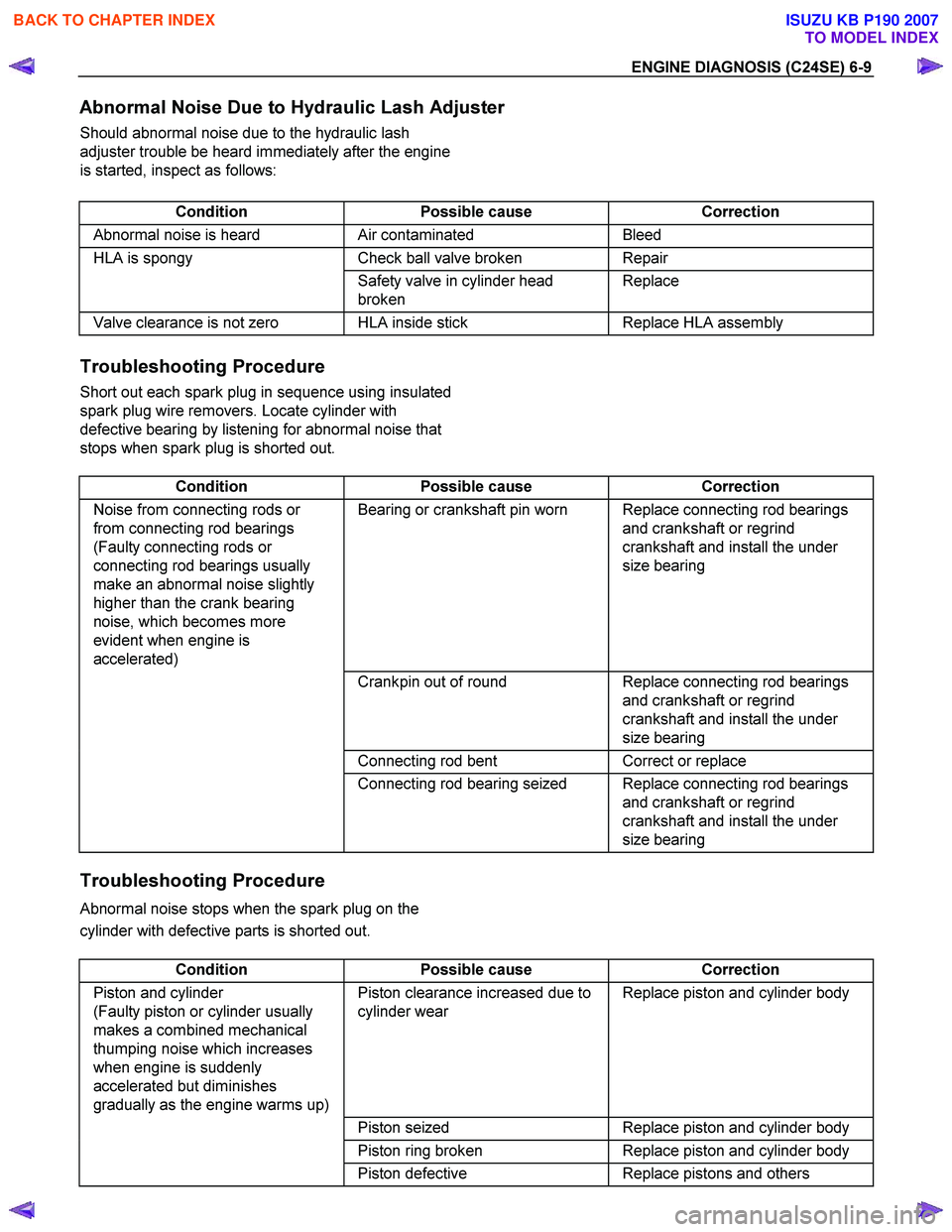
Abnormal Noise Due to Hydraulic Lash Adjuster
Should abnormal noise due to the hydraulic lash
adjuster trouble be heard immediately after the engine
is started, inspect as follows:
Condition Possible cause Correction
Abnormal noise is heard Air contaminated Bleed
HLA is spongy Check ball valve broken Repair
Safety valve in cylinder head
broken Replace
Valve clearance is not zero HLA inside stick
Replace HLA assembly
Troubleshooting Procedure
Short out each spark plug in sequence using insulated
spark plug wire removers. Locate cylinder with
defective bearing by listening for abnormal noise that
stops when spark plug is shorted out.
Condition Possible cause Correction
Noise from connecting rods or
from connecting rod bearings
(Faulty connecting rods or
connecting rod bearings usually
make an abnormal noise slightly
higher than the crank bearing
noise, which becomes more
evident when engine is
accelerated) Bearing or crankshaft pin worn Replace connecting rod bearings
and crankshaft or regrind
crankshaft and install the under
size bearing
Crankpin out of round Replace connecting rod bearings
and crankshaft or regrind
crankshaft and install the under
size bearing
Connecting rod bent Correct or replace
Connecting rod bearing seized Replace connecting rod bearings
and crankshaft or regrind
crankshaft and install the under
size bearing
Troubleshooting Procedure
Abnormal noise stops when the spark plug on the
cylinder with defective parts is shorted out.
Condition Possible cause Correction
Piston and cylinder
(Faulty piston or cylinder usually
makes a combined mechanical
thumping noise which increases
when engine is suddenly
accelerated but diminishes
gradually as the engine warms up) Piston clearance increased due to
cylinder wear Replace piston and cylinder body
Piston seized Replace piston and cylinder body
Piston ring broken Replace piston and cylinder body
Piston defective Replace pistons and others
BACK TO CHAPTER INDEX
TO MODEL INDEX
ISUZU KB P190 2007
Page 2013 of 6020
ENGINE DIAGNOSIS (C24SE) 6-13
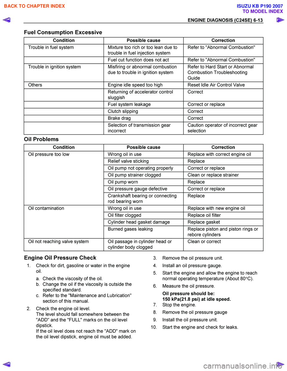
Fuel Consumption Excessive
Condition Possible cause Correction
Trouble in fuel system Mixture too rich or too lean due to
trouble in fuel injection system Refer to "Abnormal Combustion"
Fuel cut function does not act Refer to "Abnormal Combustion"
Trouble in ignition system Misfiring or abnormal combustion
due to trouble in ignition system Refer to Hard Start or Abnormal
Combustion Troubleshooting
Guide
Others Engine idle speed too high Reset Idle Air Control Valve
Returning of accelerator control
sluggish Correct
Fuel system leakage Correct or replace
Clutch slipping Correct
Brake drag Correct
Selection of transmission gear
incorrect Caution operator of incorrect gear
selection
Oil Problems
Condition Possible cause Correction
Oil pressure too low Wrong oil in use Replace with correct engine oil
Relief valve sticking Replace
Oil pump not operating properly Correct or replace
Oil pump strainer clogged Clean or replace strainer
Oil pump worn Replace
Oil pressure gauge defective Correct or replace
Crankshaft bearing or connecting
rod bearing worn Replace
Oil contamination
Wrong oil in use Replace with new engine oil
Oil filter clogged Replace oil filter
Cylinder head gasket damage Replace gasket
Burned gases leaking Replace piston and piston rings or
rebore cylinders
Oil not reaching valve system Oil passage in cylinder head or cylinder body clogged Clean or correct
Engine Oil Pressure Check
1. Check for dirt, gasoline or water in the engine
oil.
a. Check the viscosity of the oil.
b. Change the oil if the viscosity is outside the specified standard.
c. Refer to the "Maintenance and Lubrication" section of this manual.
2. Check the engine oil level. The level should fall somewhere between the
"ADD" and the "FULL" marks on the oil level
dipstick.
If the oil level does not reach the "ADD" mark on
the oil level dipstick, engine oil must be added.
3. Remove the oil pressure unit.
4. Install an oil pressure gauge.
5. Start the engine and allow the engine to reach normal operating temperature (About 80 °C).
6. Measure the oil pressure.
Oil pressure should be:
150 kPa(21.8 psi) at idle speed.
7. Stop the engine.
8. Remove the oil pressure gauge
9. Install the oil pressure unit.
10. Start the engine and check for leaks.
BACK TO CHAPTER INDEX
TO MODEL INDEX
ISUZU KB P190 2007
Page 2014 of 6020
6-14 ENGINE DIAGNOSIS (C24SE)
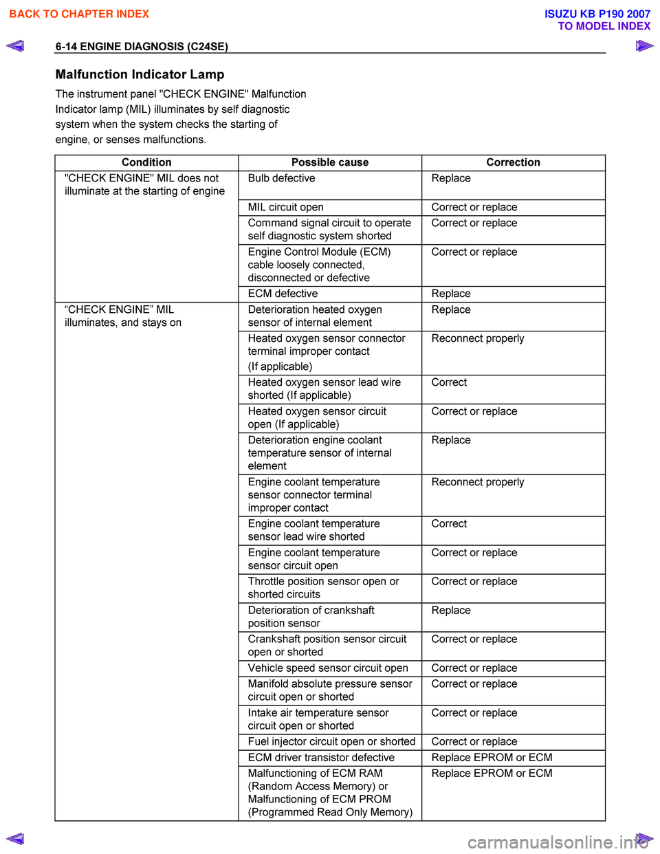
Malfunction Indicator Lamp
The instrument panel "CHECK ENGINE" Malfunction
Indicator lamp (MIL) illuminates by self diagnostic
system when the system checks the starting of
engine, or senses malfunctions.
Condition Possible cause Correction
"CHECK ENGINE" MIL does not
illuminate at the starting of engine Bulb defective Replace
MIL circuit open Correct or replace
Command signal circuit to operate
self diagnostic system shorted Correct or replace
Engine Control Module (ECM)
cable loosely connected,
disconnected or defective Correct or replace
ECM
defective Replace
“CHECK ENGINE” MIL
illuminates, and stays on Deterioration heated oxygen
sensor of internal element Replace
Heated oxygen sensor connector
terminal improper contact
(If applicable) Reconnect properly
Heated oxygen sensor lead wire
shorted (If applicable) Correct
Heated oxygen sensor circuit
open (If applicable) Correct or replace
Deterioration engine coolant
temperature sensor of internal
element Replace
Engine coolant temperature
sensor connector terminal
improper contact Reconnect properly
Engine coolant temperature
sensor lead wire shorted Correct
Engine coolant temperature
sensor circuit open Correct or replace
Throttle position sensor open or
shorted circuits Correct or replace
Deterioration of crankshaft
position sensor Replace
Crankshaft position sensor circuit
open or shorted Correct or replace
Vehicle speed sensor circuit open Correct or replace
Manifold absolute pressure sensor
circuit open or shorted Correct or replace
Intake air temperature sensor
circuit open or shorted Correct or replace
Fuel injector circuit open or shorted Correct or replace
ECM driver transistor defective Replace EPROM or ECM
Malfunctioning of ECM RAM
(Random Access Memory) or
Malfunctioning of ECM PROM
(Programmed Read Only Memory) Replace EPROM or ECM
BACK TO CHAPTER INDEX
TO MODEL INDEX
ISUZU KB P190 2007
Page 2082 of 6020
6A-68 ENGINE MECHANICAL (C24SE)
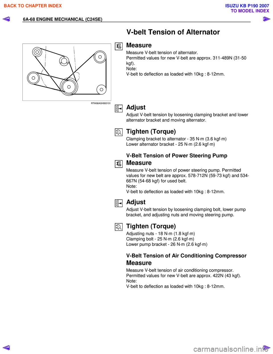
V-belt Tension of Alternator
RTW 66ASH000101
Measure
Measure V-belt tension of alternator.
Permitted values for new V-belt are approx. 311-489N (31-50
kgf).
Note:
V-belt to deflection as loaded with 10kg : 8-12mm.
Adjust
Adjust V-belt tension by loosening clamping bracket and lower
alternator bracket and moving alternator.
Tighten (Torque)
Clamping bracket to alternator - 35 N ⋅m (3.6 kgf ⋅m)
Lower alternator bracket - 25 N ⋅m (2.6 kgf ⋅m)
V-Belt Tension of Power Steering Pump
Measure
Measure V-belt tension of power steering pump. Permitted
values for new belt are approx. 578-712N (59-73 kgf) and 534-
667N (54-68 kgf) for used belt.
Note:
V-belt to deflection as loaded with 10kg : 8-12mm.
Adjust
Adjust V-belt tension by loosening clamping bolt, lower pump
bracket, and adjusting nuts and moving steering pump.
Tighten (Torque)
Adjusting nuts - 18 N ⋅m (1.8 kgf ⋅m)
Clamping bolt - 25 N ⋅m (2.6 kgf ⋅m)
Lower pump bracket - 26 N ⋅m (2.6 kgf ⋅m)
V-Belt Tension of Air Conditioning Compressor
Measure
Measure V-belt tension of air conditioning compressor.
Permitted values for new V-belt are approx. 422N (43 kgf).
Note:
V-belt to deflection as loaded with 10kg : 8-12mm.
BACK TO CHAPTER INDEX
TO MODEL INDEX
ISUZU KB P190 2007
Page 2109 of 6020
ENGINE COOLING 6B-5
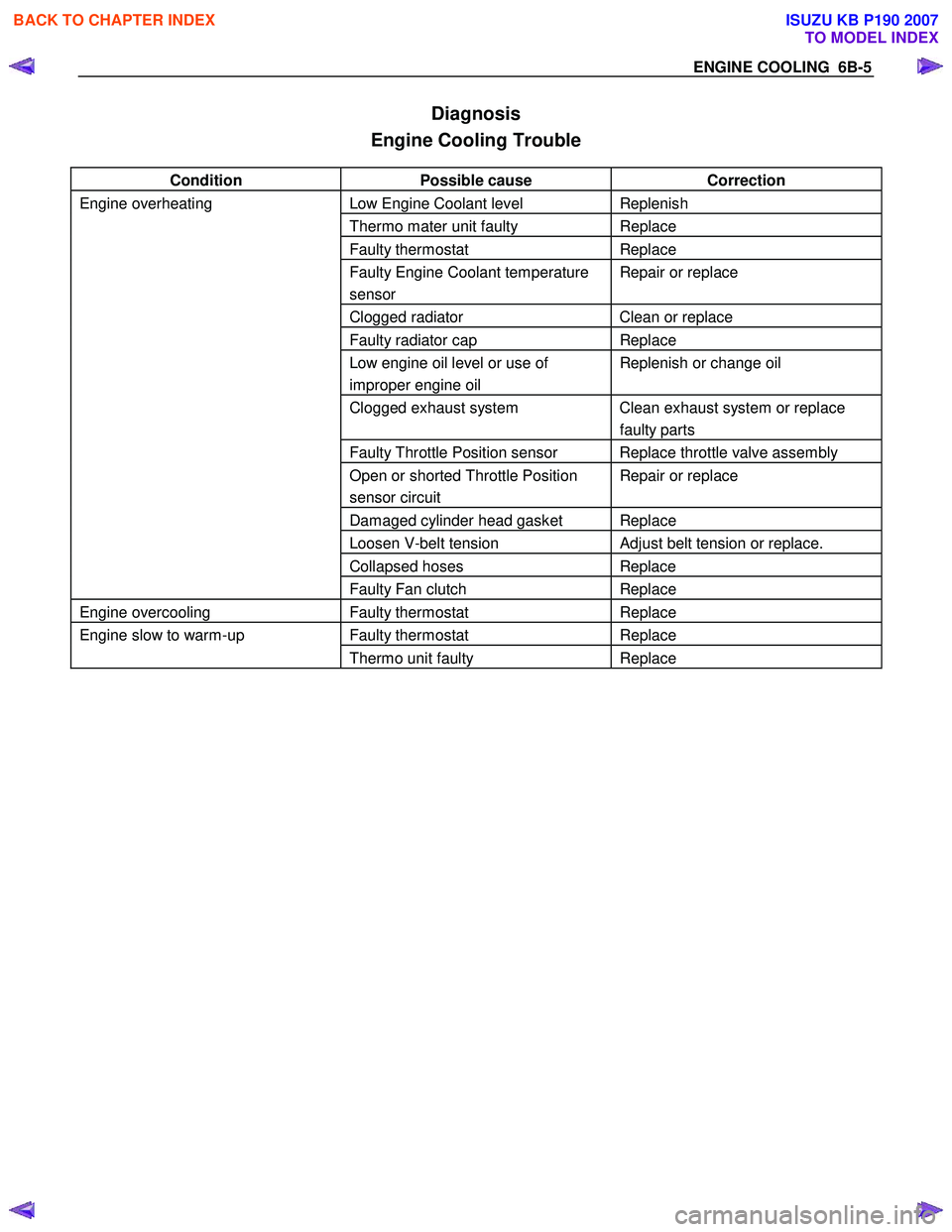
Diagnosis
Engine Cooling Trouble
Condition Possible cause Correction
Engine overheating Low Engine Coolant level Replenish
Thermo mater unit faulty Replace
Faulty thermostat Replace
Faulty Engine Coolant temperature
sensor Repair or replace
Clogged radiator Clean or replace
Faulty radiator cap Replace
Low engine oil level or use of
improper engine oil Replenish or change oil
Clogged exhaust system Clean exhaust system or replace
faulty parts
Faulty Throttle Position sensor Replace throttle valve assembly
Open or shorted Throttle Position
sensor circuit Repair or replace
Damaged cylinder head gasket Replace
Loosen V-belt tension Adjust belt tension or replace.
Collapsed hoses Replace
Faulty Fan clutch Replace
Engine overcooling Faulty thermostat Replace
Engine slow to warm-up Faulty thermostat Replace
Thermo unit faulty Replace
BACK TO CHAPTER INDEX
TO MODEL INDEX
ISUZU KB P190 2007
Page 2113 of 6020
ENGINE COOLING 6B-9
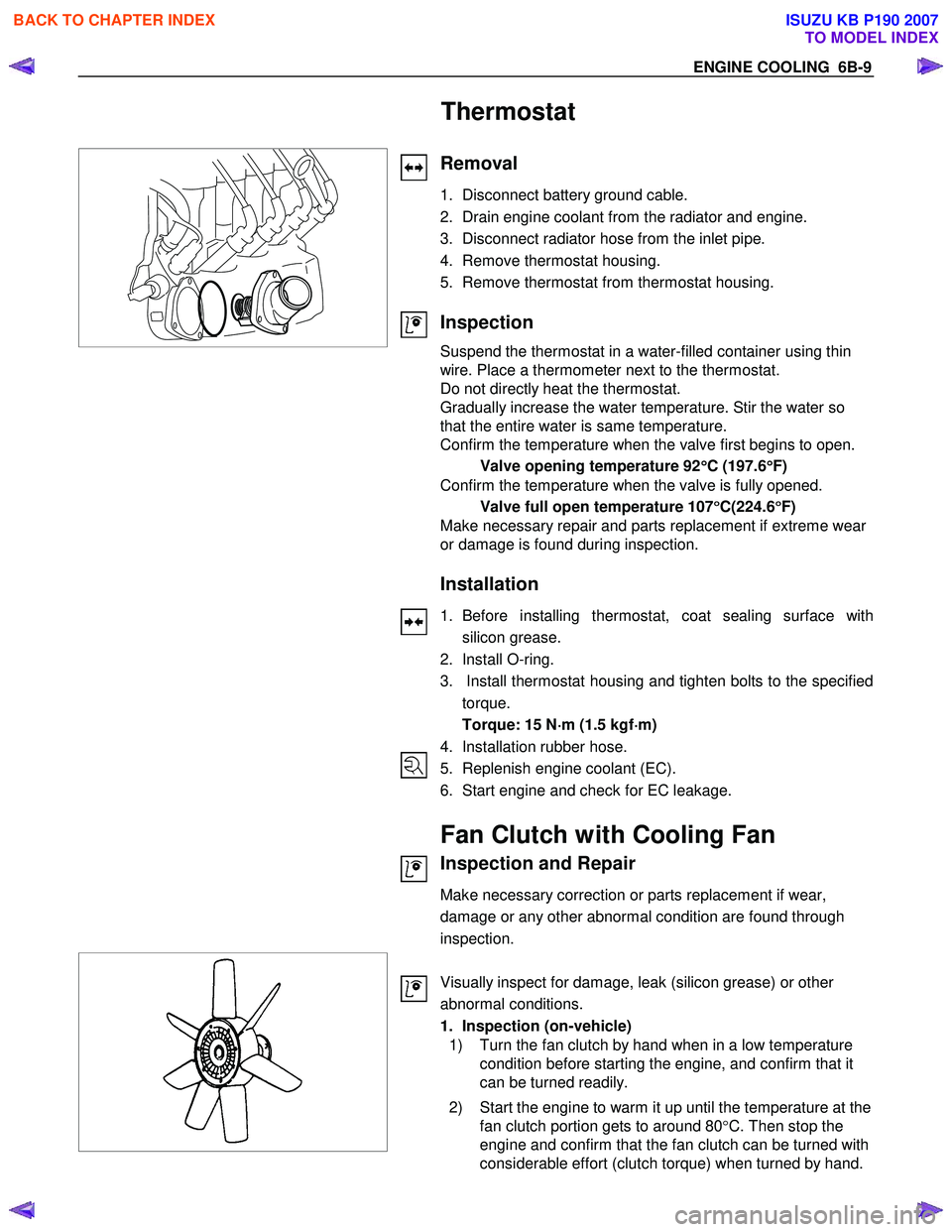
Thermostat
Removal
1. Disconnect battery ground cable.
2. Drain engine coolant from the radiator and engine.
3. Disconnect radiator hose from the inlet pipe.
4. Remove thermostat housing.
5. Remove thermostat from thermostat housing.
Inspection
Suspend the thermostat in a water-filled container using thin
wire. Place a thermometer next to the thermostat.
Do not directly heat the thermostat.
Gradually increase the water temperature. Stir the water so
that the entire water is same temperature.
Confirm the temperature when the valve first begins to open.
Valve opening temperature 92 °
°°
°
C (197.6 °
°°
°
F)
Confirm the temperature when the valve is fully opened.
Valve full open temperature 107 °
°°
°
C(224.6 °
°°
°
F)
Make necessary repair and parts replacement if extreme wear
or damage is found during inspection.
Installation
1. Before installing thermostat, coat sealing surface with
silicon grease.
2. Install O-ring.
3. Install thermostat housing and tighten bolts to the specified torque.
Torque: 15 N ⋅
⋅⋅
⋅
m (1.5 kgf ⋅
⋅⋅
⋅
m)
4. Installation rubber hose.
5. Replenish engine coolant (EC).
6. Start engine and check for EC leakage.
Fan Clutch with Cooling Fan
Inspection and Repair
Make necessary correction or parts replacement if wear,
damage or any other abnormal condition are found through
inspection.
Visually inspect for damage, leak (silicon grease) or other
abnormal conditions.
1. Inspection (on-vehicle)
1) Turn the fan clutch by hand when in a low temperature condition before starting the engine, and confirm that it
can be turned readily.
2) Start the engine to warm it up until the temperature at the fan clutch portion gets to around 80 °C. Then stop the
engine and confirm that the fan clutch can be turned with
considerable effort (clutch torque) when turned by hand.
BACK TO CHAPTER INDEX
TO MODEL INDEX
ISUZU KB P190 2007
Page 2116 of 6020
6B-12 ENGINE COOLING
Inspection
Radiator Cap
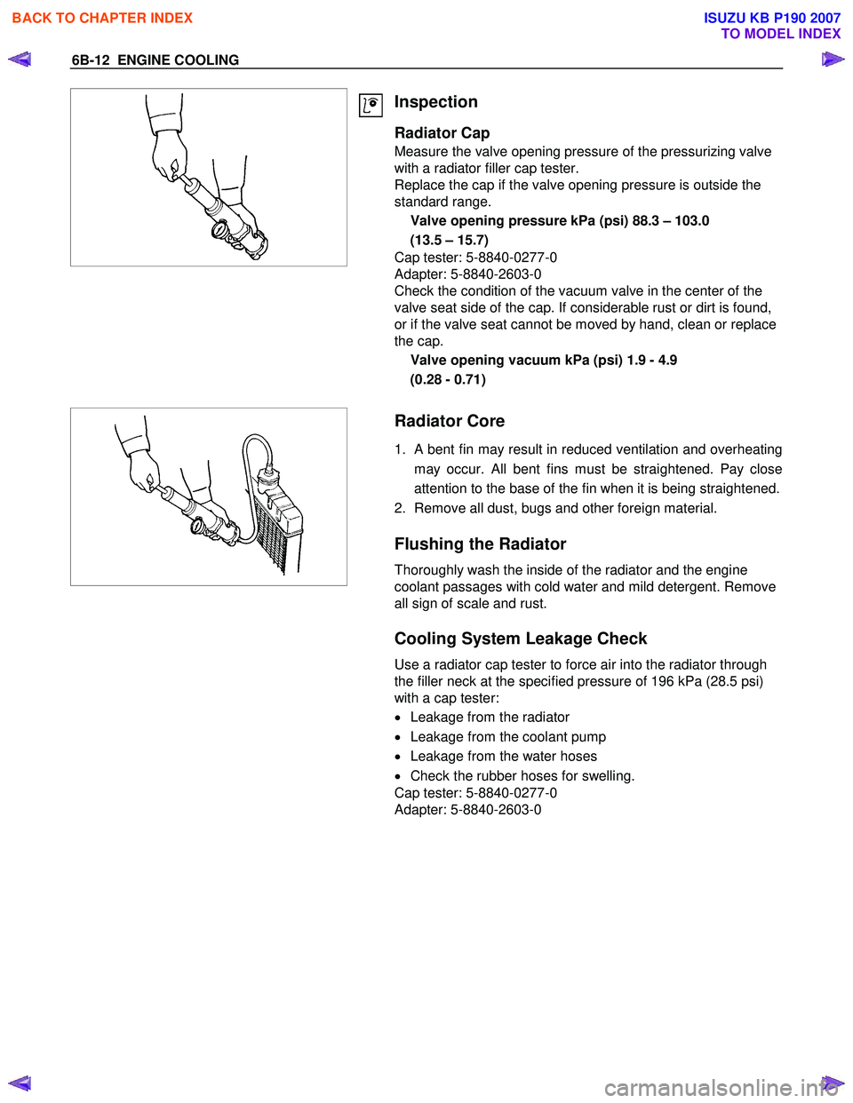
Measure the valve opening pressure of the pressurizing valve
with a radiator filler cap tester.
Replace the cap if the valve opening pressure is outside the
standard range.
Valve opening pressure kPa (psi) 88.3 – 103.0
(13.5 – 15.7)
Cap tester: 5-8840-0277-0
Adapter: 5-8840-2603-0
Check the condition of the vacuum valve in the center of the
valve seat side of the cap. If considerable rust or dirt is found,
or if the valve seat cannot be moved by hand, clean or replace
the cap.
Valve opening vacuum kPa (psi) 1.9 - 4.9
(0.28 - 0.71)
Radiator Core
1. A bent fin may result in reduced ventilation and overheating
may occur. All bent fins must be straightened. Pay close
attention to the base of the fin when it is being straightened.
2. Remove all dust, bugs and other foreign material.
Flushing the Radiator
Thoroughly wash the inside of the radiator and the engine
coolant passages with cold water and mild detergent. Remove
all sign of scale and rust.
Cooling System Leakage Check
Use a radiator cap tester to force air into the radiator through
the filler neck at the specified pressure of 196 kPa (28.5 psi)
with a cap tester:
• Leakage from the radiator
• Leakage from the coolant pump
• Leakage from the water hoses
• Check the rubber hoses for swelling.
Cap tester: 5-8840-0277-0
Adapter: 5-8840-2603-0
BACK TO CHAPTER INDEX
TO MODEL INDEX
ISUZU KB P190 2007
Page 2122 of 6020
6C-4 ENGINE FUEL (C24SE)
Fuel Metering
Engine Control Module (ECM) is in complete control of this fuel
delivery system during normal driving conditions.
The intake manifold function, like that of a diesel, is used onl
y
to let air into the engine. The fuel is injected by separate
injectors that are mounted over the intake manifold.
The Manifold Absolute Pressure (MAP) sensor measures the
changes in the intake manifold pressure which result from
engine load and speed changes, which the MAP senso
r
converts to a voltage output.
This sensor generates the voltage to change corresponding to
the flow of the air drawn into the engine.
The changing voltage is transformed into an electric signal and
provided to the ECM.
W ith receipt of the signals sent from the MAP sensor, Intake
Air Temperature sensor and others, the ECM determines an
appropriate fuel injection pulse width feeding such information
to the fuel injector valves to effect an appropriate air/fuel ratio.
The Multiport Fuel Injection system utilizes an injection system
where the injectors turn on at every crankshaft revolution. The
ECM controls the injector on time so that the correct amount o
f
fuel is metered depending on driving conditions.
Two interchangeable "O" rings are used on the injector that
must be replaced when the injectors are removed.
The fuel rail is attached to the top of the intake manifold and
supplies fuel to all the injectors.
Fuel is recirculated through the rail continually while the engine
is running. This removes air and vapors from the fuel as well
as keeping the fuel cool during hot weather operation.
The fuel pressure control valve that is mounted on the fuel rail
maintains a pressure differential across the injectors under all
operating conditions. It is accomplished by controlling the
amount of fuel that is recirculated back to the fuel tank based
on engine demand.
See Section "Driveability and Emission" for more information
and diagnosis.
BACK TO CHAPTER INDEX
TO MODEL INDEX
ISUZU KB P190 2007