2007 ISUZU KB P190 DTC CHECK
[x] Cancel search: DTC CHECKPage 3499 of 6020
Engine Management – V6 – Diagnostics Page 6C1-2–221
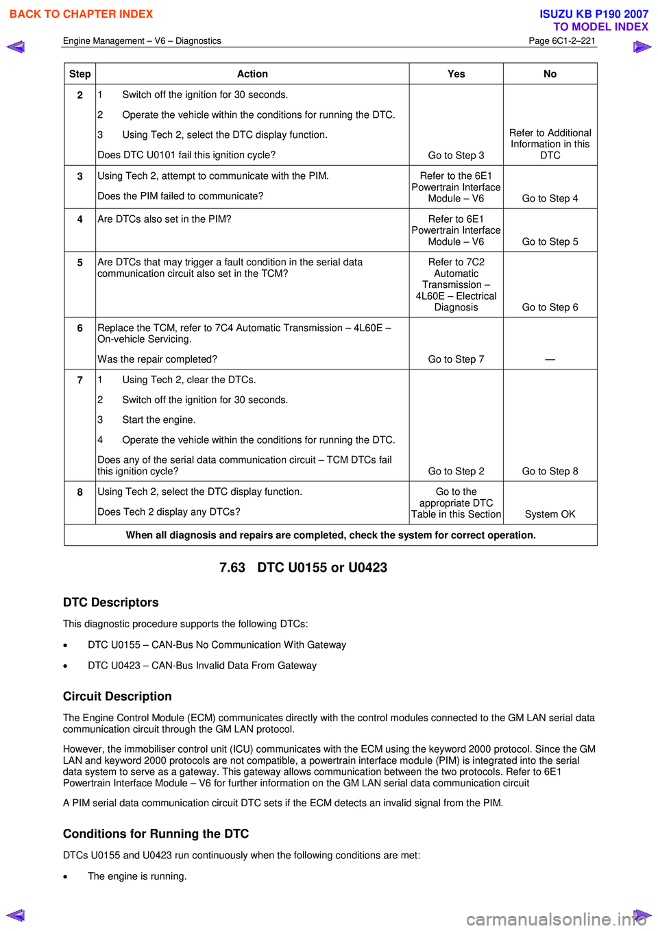
Step Action Yes No
2 1 Switch off the ignition for 30 seconds.
2 Operate the vehicle within the conditions for running the DTC.
3 Using Tech 2, select the DTC display function.
Does DTC U0101 fail this ignition cycle? Go to Step 3 Refer to Additional
Information in this DTC
3 Using Tech 2, attempt to communicate with the PIM.
Does the PIM failed to communicate? Refer to the 6E1
Powertrain Interface Module – V6 Go to Step 4
4 Are DTCs also set in the PIM? Refer to 6E1
Powertrain Interface Module – V6 Go to Step 5
5 Are DTCs that may trigger a fault condition in the serial data
communication circuit also set in the TCM? Refer to 7C2
Automatic
Transmission –
4L60E – Electrical Diagnosis Go to Step 6
6 Replace the TCM, refer to 7C4 Automatic Transmission – 4L60E –
On-vehicle Servicing.
W as the repair completed? Go to Step 7 —
7 1 Using Tech 2, clear the DTCs.
2 Switch off the ignition for 30 seconds.
3 Start the engine.
4 Operate the vehicle within the conditions for running the DTC.
Does any of the serial data communication circuit – TCM DTCs fail
this ignition cycle? Go to Step 2 Go to Step 8
8 Using Tech 2, select the DTC display function.
Does Tech 2 display any DTCs? Go to the
appropriate DTC
Table in this Section System OK
When all diagnosis and repairs are completed, check the system for correct operation.
7.63 DTC U0155 or U0423
DTC Descriptors
This diagnostic procedure supports the following DTCs:
• DTC U0155 – CAN-Bus No Communication W ith Gateway
• DTC U0423 – CAN-Bus Invalid Data From Gateway
Circuit Description
The Engine Control Module (ECM) communicates directly with the control modules connected to the GM LAN serial data
communication circuit through the GM LAN protocol.
However, the immobiliser control unit (ICU) communicates with the ECM using the keyword 2000 protocol. Since the GM
LAN and keyword 2000 protocols are not compatible, a powertrain interface module (PIM) is integrated into the serial
data system to serve as a gateway. This gateway allows communication between the two protocols. Refer to 6E1
Powertrain Interface Module – V6 for further information on the GM LAN serial data communication circuit
A PIM serial data communication circuit DTC sets if the ECM detects an invalid signal from the PIM.
Conditions for Running the DTC
DTCs U0155 and U0423 run continuously when the following conditions are met:
• The engine is running.
BACK TO CHAPTER INDEX
TO MODEL INDEX
ISUZU KB P190 2007
Page 3500 of 6020
Engine Management – V6 – Diagnostics Page 6C1-2–222
• The ignition voltage is 10.0 – 16.0 V.
Conditions for Setting the DTC
The ECM did not receive a valid signal from the PIM within the specified time frame.
Conditions for Clearing the DTC
The PIM serial data communication circuit DTCs are Type C DTCs. Refer to 1.4 Diagnostic Trouble Codes in this
Section, for action taken when a Type C DTC sets and conditions for clearing Type C DTCs.
Additional Information
• Refer to 6C1-1 Engine Management – V6 – General Information for details of the ECM operation.
• Since fault condition in a wiring connector may trigger DTCs, always test the connectors related to this diagnostic
procedure for shorted terminals or poor wiring connection before replacing any component. Refer to 8A Electrical -
Body and Chassis for information on electrical fault diagnosis.
• For an intermittent fault condition, refer to 5.2 Intermittent Fault Conditions in this Section.
• To assist diagnosis, refer to 3 W iring Diagrams and Connector Charts in this Section, for the system wiring
diagram and connector charts.
Test Description
The following number refers to the step numbers in the diagnostic table:
1 The following tests are included in the Diagnostic System Check.
• Tests the integrity of the GM LAN serial data communication circuit.
• Tests for fault conditions on the vehicle immobiliser system stored in the ICU.
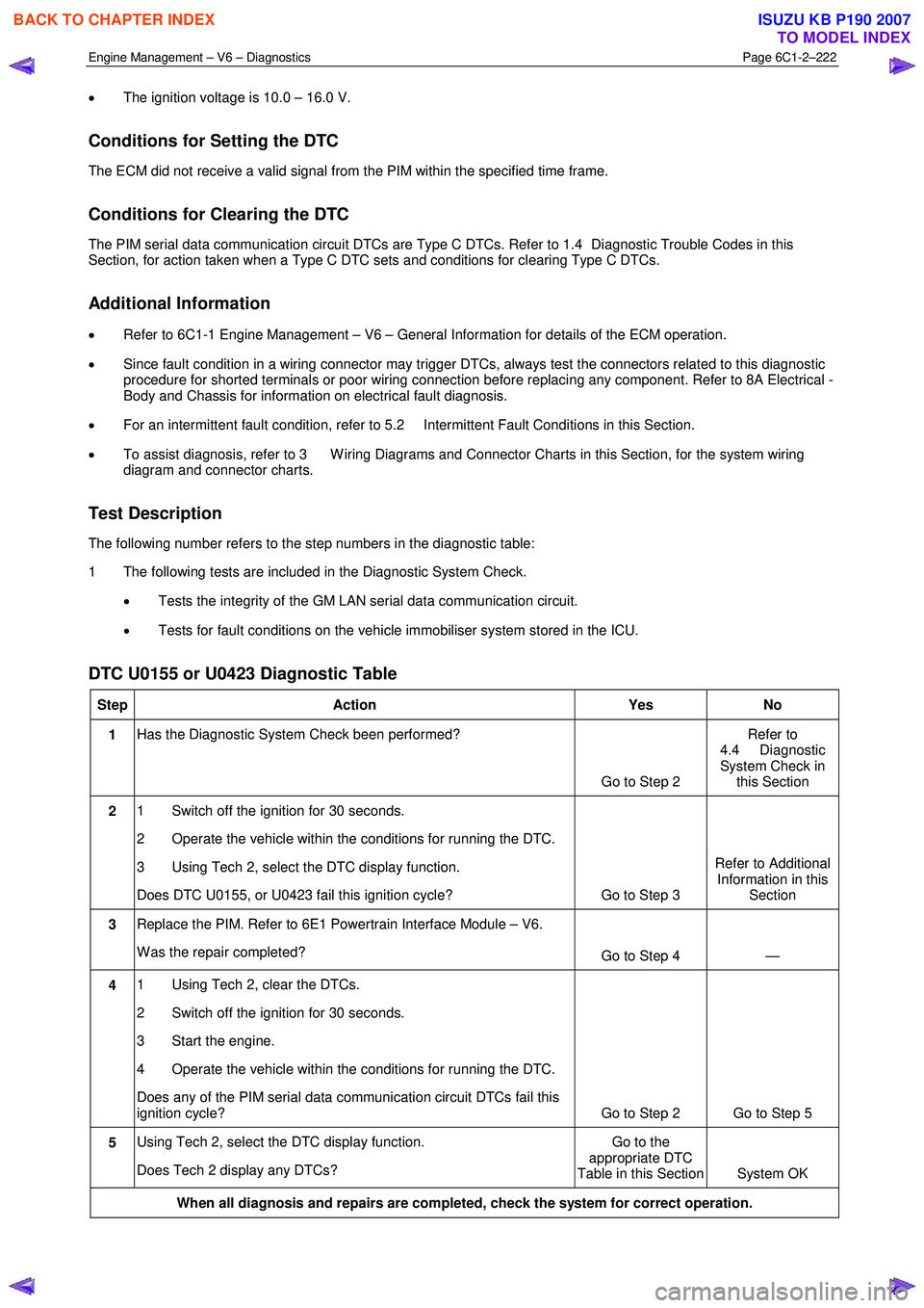
DTC U0155 or U0423 Diagnostic Table
Step Action Yes No
1 Has the Diagnostic System Check been performed?
Go to Step 2 Refer to
4.4 Diagnostic
System Check in this Section
2 1 Switch off the ignition for 30 seconds.
2 Operate the vehicle within the conditions for running the DTC.
3 Using Tech 2, select the DTC display function.
Does DTC U0155, or U0423 fail this ignition cycle? Go to Step 3 Refer to Additional
Information in this Section
3 Replace the PIM. Refer to 6E1 Powertrain Interface Module – V6.
W as the repair completed? Go to Step 4 —
4 1 Using Tech 2, clear the DTCs.
2 Switch off the ignition for 30 seconds.
3 Start the engine.
4 Operate the vehicle within the conditions for running the DTC.
Does any of the PIM serial data communication circuit DTCs fail this
ignition cycle? Go to Step 2 Go to Step 5
5 Using Tech 2, select the DTC display function.
Does Tech 2 display any DTCs? Go to the
appropriate DTC
Table in this Section System OK
When all diagnosis and repairs are completed, check the system for correct operation.
BACK TO CHAPTER INDEX
TO MODEL INDEX
ISUZU KB P190 2007
Page 3501 of 6020
Engine Management – V6 – Diagnostics Page 6C1-2–223
8 HFV6 Engine – Tech 2 Functions
8.1 Introduction
Do not use a Tech 2 that displays faulty data;
have the Tech 2 repaired. The use of a faulty
Tech 2 can result in misdiagnosis and the
unnecessary replacement of parts.
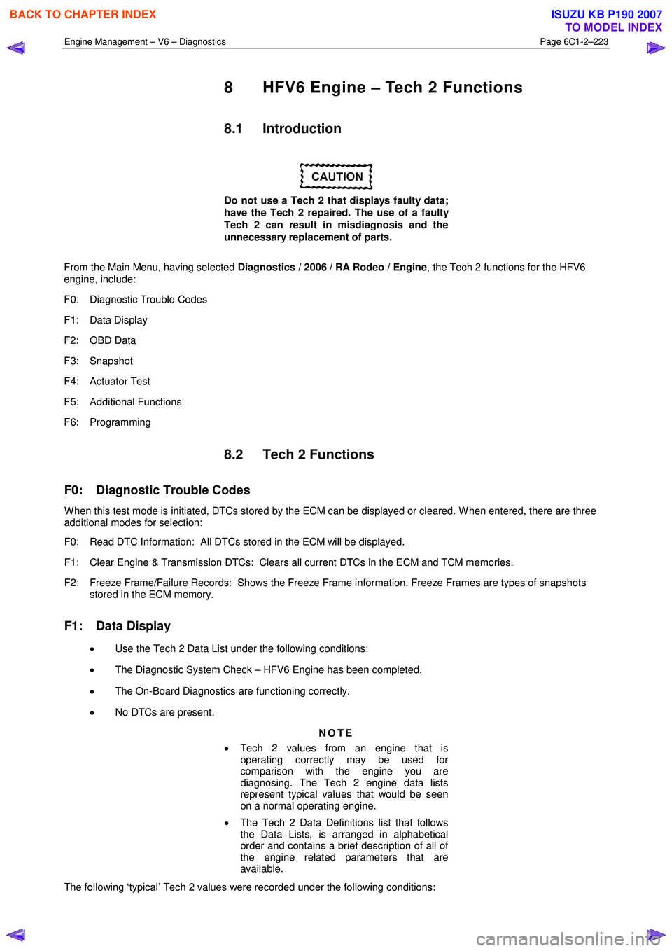
From the Main Menu, having selected Diagnostics / 2006 / RA Rodeo / Engine , the Tech 2 functions for the HFV6
engine, include:
F0: Diagnostic Trouble Codes
F1: Data Display
F2: OBD Data
F3: Snapshot
F4: Actuator Test
F5: Additional Functions
F6: Programming
8.2 Tech 2 Functions
F0: Diagnostic Trouble Codes
W hen this test mode is initiated, DTCs stored by the ECM can be displayed or cleared. W hen entered, there are three
additional modes for selection:
F0: Read DTC Information: All DTCs stored in the ECM will be displayed.
F1: Clear Engine & Transmission DTCs: Clears all current DTCs in the ECM and TCM memories.
F2: Freeze Frame/Failure Records: Shows the Freeze Frame information. Freeze Frames are types of snapshots stored in the ECM memory.
F1: Data Display
• Use the Tech 2 Data List under the following conditions:
• The Diagnostic System Check – HFV6 Engine has been completed.
• The On-Board Diagnostics are functioning correctly.
• No DTCs are present.
NOTE
• Tech 2 values from an engine that is
operating correctly may be used for
comparison with the engine you are
diagnosing. The Tech 2 engine data lists
represent typical values that would be seen
on a normal operating engine.
• The Tech 2 Data Definitions list that follows
the Data Lists, is arranged in alphabetical
order and contains a brief description of all of
the engine related parameters that are
available.
The following ‘typical’ Tech 2 values were recorded under the following conditions:
BACK TO CHAPTER INDEX
TO MODEL INDEX
ISUZU KB P190 2007
Page 3594 of 6020
Charging System – V6 Page 6D1-1-7
2 Diagnosis
2.1 Diagnostic General Information
Basic Diagnostic Tools Required
Use of incorrect electrical circuit diagnostic
tools when performing the generator
diagnostic procedures could result in
incorrect diagnostic results or damage to
components.
The following electrical circuit testing tools are required to perform the diagnostic procedures detailed in this Section:
• digital multimeter with 10 mega ohms impedance, and
• connector test adapter kit Tool No. KM609.
For further information on the use of these tools, refer to 8A Electrical Body and Chassis.
2.2 Tech 2 Data List
The Tech 2 displays the status of certain charging system parameters.
To view the data list:
1 Connect Tech 2 to the DLC.
2 On Tech 2 select: Engine / V6 Engine / Data Display / Data List / Electrical/Theft Data .
Tech 2 Parameter Units Displayed Typical Display Values
Alternator L Terminal D Percentage Various
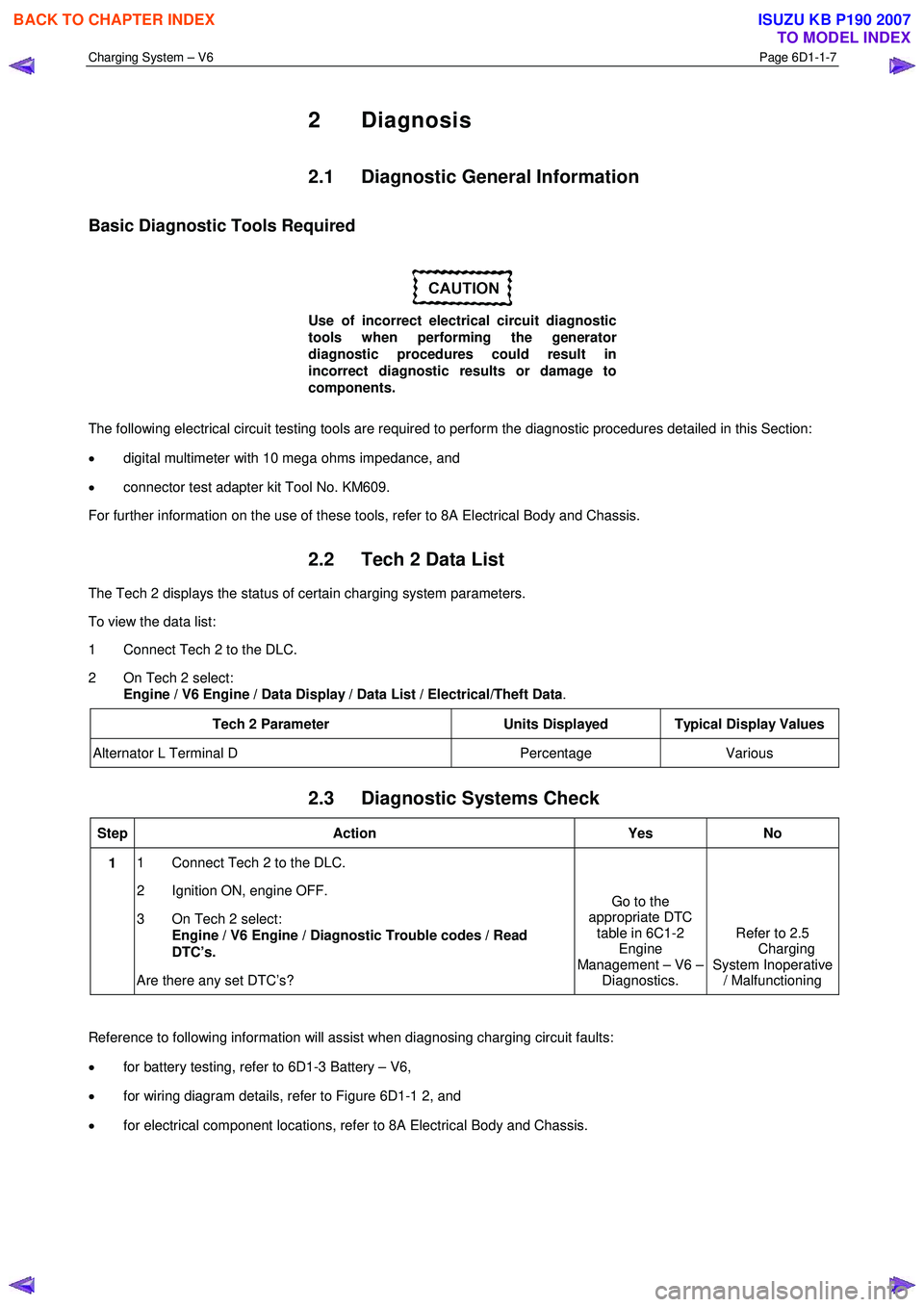
2.3 Diagnostic Systems Check
Step Action Yes No
1 1 Connect Tech 2 to the DLC.
2 Ignition ON, engine OFF.
3 On Tech 2 select: Engine / V6 Engine / Diagnostic Trouble codes / Read
DTC’s.
Are there any set DTC’s? Go to the
appropriate DTC table in 6C1-2 Engine
Management – V6 – Diagnostics. Refer to 2.5
Charging
System Inoperative / Malfunctioning
Reference to following information will assist when diagnosing charging circuit faults:
• for battery testing, refer to 6D1-3 Battery – V6,
• for wiring diagram details, refer to Figure 6D1-1 2, and
• for electrical component locations, refer to 8A Electrical Body and Chassis.
BACK TO CHAPTER INDEX
TO MODEL INDEX
ISUZU KB P190 2007
Page 3615 of 6020
Starting System – V6 Page 6D1-2–7
2 Diagnostics
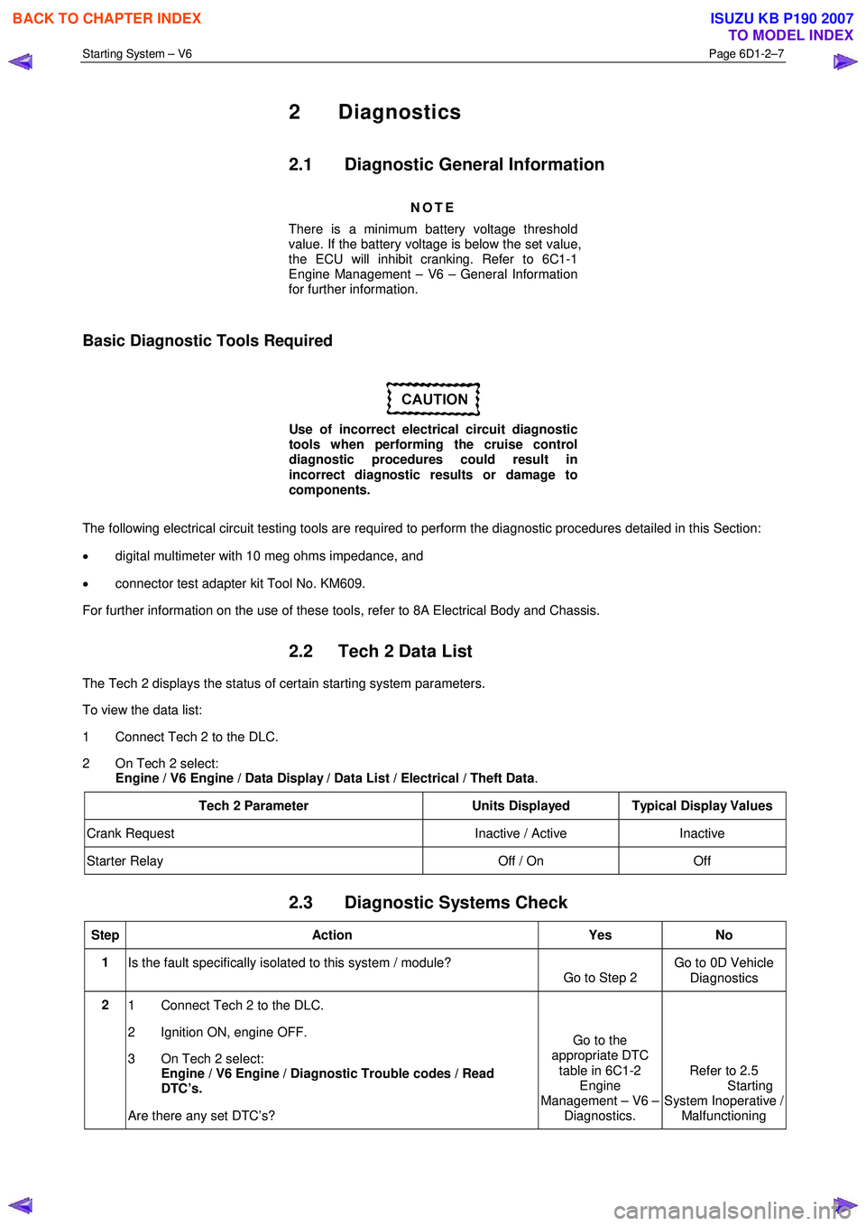
2.1 Diagnostic General Information
NOTE
There is a minimum battery voltage threshold
value. If the battery voltage is below the set value,
the ECU will inhibit cranking. Refer to 6C1-1
Engine Management – V6 – General Information
for further information.
Basic Diagnostic Tools Required
Use of incorrect electrical circuit diagnostic
tools when performing the cruise control
diagnostic procedures could result in
incorrect diagnostic results or damage to
components.
The following electrical circuit testing tools are required to perform the diagnostic procedures detailed in this Section:
• digital multimeter with 10 meg ohms impedance, and
• connector test adapter kit Tool No. KM609.
For further information on the use of these tools, refer to 8A Electrical Body and Chassis.
2.2 Tech 2 Data List
The Tech 2 displays the status of certain starting system parameters.
To view the data list:
1 Connect Tech 2 to the DLC.
2 On Tech 2 select: Engine / V6 Engine / Data Display / Data List / Electrical / Theft Data .
Tech 2 Parameter Units Displayed Typical Display Values
Crank Request Inactive / Active Inactive
Starter Relay Off / On Off
2.3 Diagnostic Systems Check
Step Action Yes No
1
Is the fault specifically isolated to this system / module?
Go to Step 2 Go to 0D Vehicle
Diagnostics
2 1 Connect Tech 2 to the DLC.
2 Ignition ON, engine OFF.
3 On Tech 2 select:
Engine / V6 Engine / Diagnostic Trouble codes / Read
DTC’s.
Are there any set DTC’s? Go to the
appropriate DTC
table in 6C1-2 Engine
Management – V6 – Diagnostics. Refer to 2.5
Starting
System Inoperative / Malfunctioning
BACK TO CHAPTER INDEX
TO MODEL INDEX
ISUZU KB P190 2007
Page 3647 of 6020
Battery Page 6D1-3–7
3 Diagnosis
3.1 Diagnostic Procedures
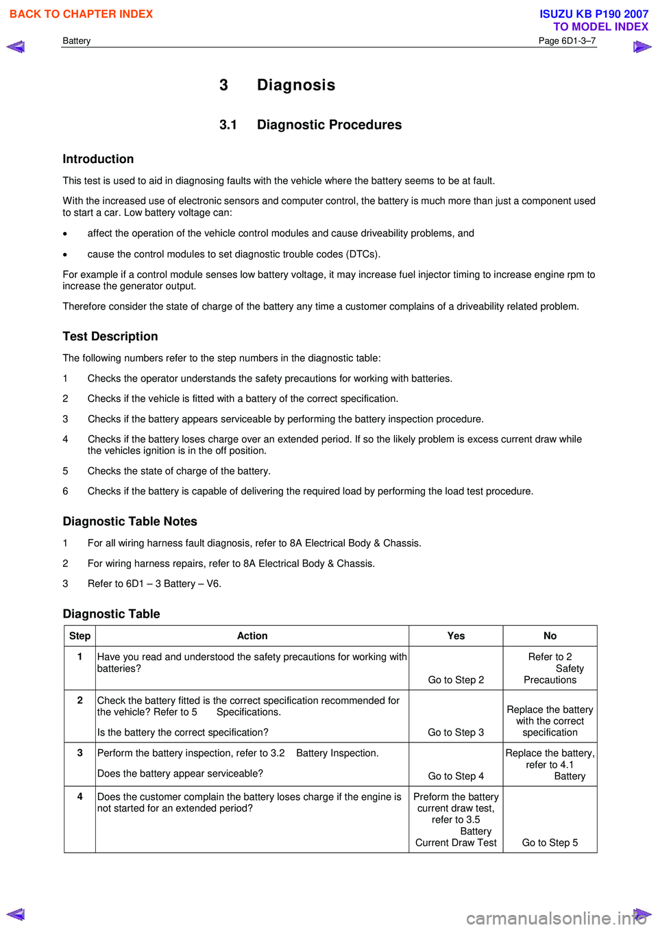
Introduction
This test is used to aid in diagnosing faults with the vehicle where the battery seems to be at fault.
W ith the increased use of electronic sensors and computer control, the battery is much more than just a component used
to start a car. Low battery voltage can:
• affect the operation of the vehicle control modules and cause driveability problems, and
• cause the control modules to set diagnostic trouble codes (DTCs).
For example if a control module senses low battery voltage, it may increase fuel injector timing to increase engine rpm to
increase the generator output.
Therefore consider the state of charge of the battery any time a customer complains of a driveability related problem.
Test Description
The following numbers refer to the step numbers in the diagnostic table:
1 Checks the operator understands the safety precautions for working with batteries.
2 Checks if the vehicle is fitted with a battery of the correct specification.
3 Checks if the battery appears serviceable by performing the battery inspection procedure.
4 Checks if the battery loses charge over an extended period. If so the likely problem is excess current draw while the vehicles ignition is in the off position.
5 Checks the state of charge of the battery.
6 Checks if the battery is capable of delivering the required load by performing the load test procedure.
Diagnostic Table Notes
1 For all wiring harness fault diagnosis, refer to 8A Electrical Body & Chassis.
2 For wiring harness repairs, refer to 8A Electrical Body & Chassis.
3 Refer to 6D1 – 3 Battery – V6.
Diagnostic Table
Step Action Yes No
1
Have you read and understood the safety precautions for working with
batteries? Go to Step 2 Refer to 2
Safety Precautions
2 Check the battery fitted is the correct specification recommended for
the vehicle? Refer to 5 Specifications.
Is the battery the correct specification? Go to Step 3 Replace the battery
with the correct
specification
3 Perform the battery inspection, refer to 3.2 Battery Inspection.
Does the battery appear serviceable? Go to Step 4 Replace the battery,
refer to 4.1
Battery
4 Does the customer complain the battery loses charge if the engine is
not started for an extended period? Preform the battery
current draw test, refer to 3.5
Battery
Current Draw Test Go to Step 5
BACK TO CHAPTER INDEX
TO MODEL INDEX
ISUZU KB P190 2007
Page 3662 of 6020
Powertrain Interface Module – V6 Page 6E1–1
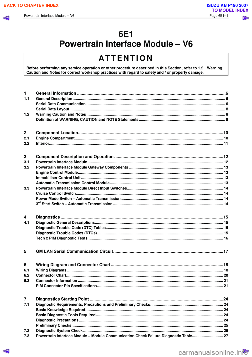
6E1
Powertrain Interface Module – V6
ATTENTION
Before performing any service operation or other procedure described in this Section, refer to 1.2 Warning
Caution and Notes for correct workshop practices with regard to safety and / or property damage.
1 General Information ............................................................................................................ ...................6
1.1 General Description ............................................................................................................ ................................... 6
Serial Data Communication .................................................................................................................................. 6
Serial Data Layout.................................................................................................................................................. 8
1.2 Warning Caution and Notes .................................................................................................................................. 8
Definition of WARNING, CAUTION and NOTE Statements ............................................................................. .... 8
2 Component Location............................................................................................................................10
2.1 Engine Compartment............................................................................................................. .............................. 10
2.2 Interior................................................................................................................................................................... 11
3 Component Description and Operation ............................................................................................ .12
3.1 Powertrain Interface Module ............................................................................................................................... 12
3.2 Powertrain Interface Module Gateway Components ................................................................................. ....... 13
Engine Control Module........................................................................................................................................ 13
Immobiliser Control Unit ..................................................................................................................................... 13
Automatic Transmission Control Module .......................................................................................... ................ 13
3.3 Powertrain Interface Module Direct Input Switches.............................................................................. ............ 14
Cruise Control Switch.......................................................................................................................................... 14
Power Mode Switch – Automatic Transmission..................................................................................... ........... 14
3rd Start Switch – Automatic Transmission ....................................................................................................... 14
4 Diagnostics ...........................................................................................................................................15
4.1 Diagnostic General Descriptions................................................................................................ ........................ 15
Diagnostic Trouble Code (DTC) Tables........................................................................................... ................... 15
Diagnostic Trouble Codes (DTCs) ...................................................................................................................... 15
Tech 2 PIM Diagnostic Tests............................................................................................................................... 16
5 GM LAN Serial Communication Circuit ............................................................................................ ..17
6 Wiring Diagram and Connector Chart ................................................................................................18
6.1 Wiring Diagrams .................................................................................................................................................. 18
6.2 Connector Chart................................................................................................................................................... 20
6.3 Connector Information .......................................................................................................... .............................. 21
PIM Connector Pin Specifications ............................................................................................... ....................... 21
7 Diagnostics Starting Point ..................................................................................................................24
7.1 Diagnostic Requirements, Precautions and Preliminary Checks .................................................................... 24
Basic Knowledge Required ................................................................................................................................. 24
Basic Diagnostic Tools Required ................................................................................................ ....................... 24
Diagnostic Precautions ....................................................................................................................................... 24
Preliminary Checks.............................................................................................................................................. 25
7.2 Diagnostic System Check ........................................................................................................ ........................... 25
7.3 Powertrain Interface Module – Module Communication Check Failure Diagnostic Table............................. 27
BACK TO CHAPTER INDEX
TO MODEL INDEX
ISUZU KB P190 2007
Page 3676 of 6020
Powertrain Interface Module – V6 Page 6E1–15
4 Diagnostics
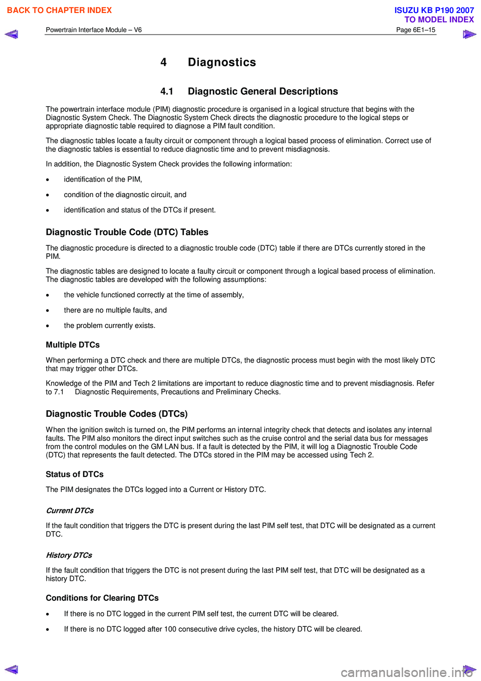
4.1 Diagnostic General Descriptions
The powertrain interface module (PIM) diagnostic procedure is organised in a logical structure that begins with the
Diagnostic System Check. The Diagnostic System Check directs the diagnostic procedure to the logical steps or
appropriate diagnostic table required to diagnose a PIM fault condition.
The diagnostic tables locate a faulty circuit or component through a logical based process of elimination. Correct use of
the diagnostic tables is essential to reduce diagnostic time and to prevent misdiagnosis.
In addition, the Diagnostic System Check provides the following information:
• identification of the PIM,
• condition of the diagnostic circuit, and
• identification and status of the DTCs if present.
Diagnostic Trouble Code (DTC) Tables
The diagnostic procedure is directed to a diagnostic trouble code (DTC) table if there are DTCs currently stored in the
PIM.
The diagnostic tables are designed to locate a faulty circuit or component through a logical based process of elimination.
The diagnostic tables are developed with the following assumptions:
• the vehicle functioned correctly at the time of assembly,
• there are no multiple faults, and
• the problem currently exists.
Multiple DTCs
W hen performing a DTC check and there are multiple DTCs, the diagnostic process must begin with the most likely DTC
that may trigger other DTCs.
Knowledge of the PIM and Tech 2 limitations are important to reduce diagnostic time and to prevent misdiagnosis. Refer
to 7.1 Diagnostic Requirements, Precautions and Preliminary Checks.
Diagnostic Trouble Codes (DTCs)
W hen the ignition switch is turned on, the PIM performs an internal integrity check that detects and isolates any internal
faults. The PIM also monitors the direct input switches such as the cruise control and the serial data bus for messages
from the control modules on the GM LAN bus. If a fault is detected by the PIM, it will log a Diagnostic Trouble Code
(DTC) that represents the fault detected. The DTCs stored in the PIM may be accessed using Tech 2.
Status of DTCs
The PIM designates the DTCs logged into a Current or History DTC.
Current DTCs
If the fault condition that triggers the DTC is present during the last PIM self test, that DTC will be designated as a current
DTC.
History DTCs
If the fault condition that triggers the DTC is not present during the last PIM self test, that DTC will be designated as a
history DTC.
Conditions for Clearing DTCs
• If there is no DTC logged in the current PIM self test, the current DTC will be cleared.
• If there is no DTC logged after 100 consecutive drive cycles, the history DTC will be cleared.
BACK TO CHAPTER INDEX
TO MODEL INDEX
ISUZU KB P190 2007