2007 ISUZU KB P190 sensor
[x] Cancel search: sensorPage 1979 of 6020

6E-362 ENGINE CONTROL SYSTEM (4JK1/4JJ1)
Fuel Supply Pump
The fuel supply pump is the heart of the common rail
type electronic fuel injection system. The fuel supply
pump is installed at the same location as the
conventional injection type pump, which spins at a 1 to
1 ratio of fuel supply pump to crankshaft speed. A fuel
rail pressure (FRP) regulator and fuel temperature
sensor are part of the fuel supply pump assembly.
Fuel is drawn from the fuel tank via the fuel supply
pump by the use of an internal feed pump (trochoid
type). This feed pump pumps fuel into a 2-plunger
chamber also internal to the fuel supply pump. Fuel into
this chamber is regulated by the FRP regulator solely
controlled by current supplied from the ECM. No
current to the solenoid results in maximum fuel flow
whereas full current to the solenoid produces no fuel
flow. As the engine spins, these two plungers produce
high pressure in the fuel rail. Since the ECM controls
the flow of fuel into this 2-plunger chamber, it therefore
controls the quantity and pressure of the fuel supply to
the fuel rail. This optimizes performance, improves
economy and reduces NOx emissions. Fuel Rail (Common Rail)
Legend
1. Pressure limiter valve
2. Fuel rail pressure (FRP) sensor
RTW76EMF000201
Suction pressure
Feed pressure
Return pressure
High pressure
Fuel rail
Injector
Delivery valve Cuction valve
Plunger
Fuel inletRegulation valve
Driveshaft
Fuel overflow
Feed pump
Return spring
Fuel tank Fuel filter
Return
SuctionFRP regulator
RTW76ESH002001
1
2
BACK TO CHAPTER INDEX
TO MODEL INDEX
ISUZU KB P190 2007
Page 1980 of 6020
ENGINE CONTROL SYSTEM (4JK1/4JJ1) 6E-363
Along with the employment of a common rail type
electronic control fuel injection system, the fuel rail is
provided to store high pressure fuel between supply
pump and injectors. A pressure sensor and a pressure
limiter are installed on the fuel rail. The pressure sensor
detects the fuel pressure inside the fuel rail and sends
its signal to the ECM. Based on this signal, the ECM
controls the fuel pressure inside the fuel rail via the fuel
rail pressure (FRP) regulator of the supply pump. The
pressure limiter opens the valve mechanically to relieve
the pressure when the fuel pressure inside the fuel rail
is excessive.
Fuel Rail Pressure Sensor
The FRP sensor is installed to the fuel rail and it
detects the fuel pressure in the fuel rail, converts the
pressure into a voltage signal, and sends the signal to
the ECM. The ECM monitors the FRP sensor signal
voltage. Higher fuel rail pressure provides higher signal
voltage while lower pressure provides lower signal
voltage. The ECM calculates actual fuel rail pressure
(fuel pressure) from the voltage signal and uses the
result in fuel injection control and other control tasks.
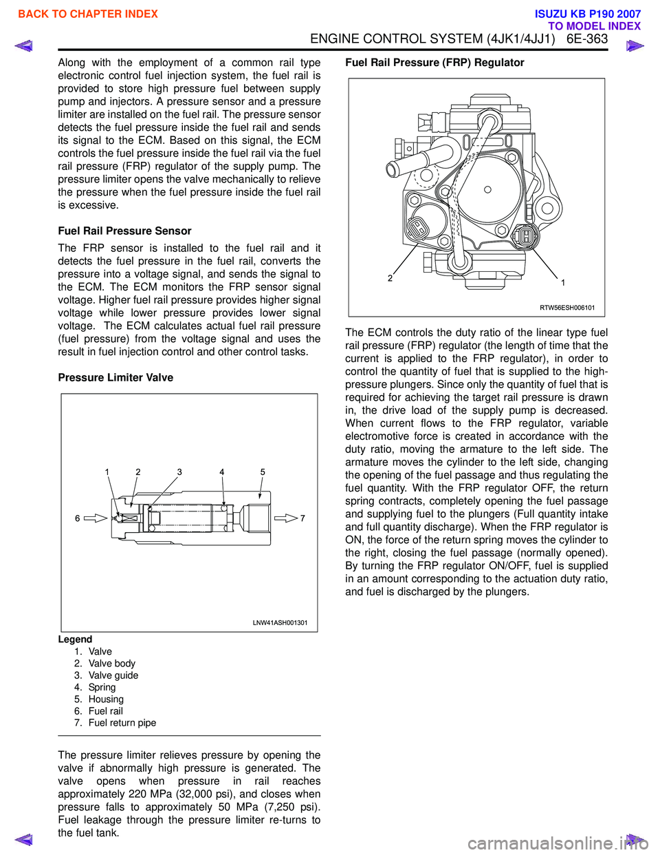
Pressure Limiter Valve
Legend 1. Valve
2. Valve body
3. Valve guide
4. Spring
5. Housing
6. Fuel rail
7. Fuel return pipe
The pressure limiter relieves pressure by opening the
valve if abnormally high pressure is generated. The
valve opens when pressure in rail reaches
approximately 220 MPa (32,000 psi), and closes when
pressure falls to approximately 50 MPa (7,250 psi).
Fuel leakage through the pressure limiter re-turns to
the fuel tank. Fuel Rail Pressure (FRP) Regulator
The ECM controls the duty ratio of the linear type fuel
rail pressure (FRP) regulator (the length of time that the
current is applied to the FRP regulator), in order to
control the quantity of fuel that is supplied to the high-
pressure plungers. Since only the quantity of fuel that is
required for achieving the target rail pressure is drawn
in, the drive load of the supply pump is decreased.
When current flows to the FRP regulator, variable
electromotive force is created in accordance with the
duty ratio, moving the armature to the left side. The
armature moves the cylinder to the left side, changing
the opening of the fuel passage and thus regulating the
fuel quantity. With the FRP regulator OFF, the return
spring contracts, completely opening the fuel passage
and supplying fuel to the plungers (Full quantity intake
and full quantity discharge). When the FRP regulator is
ON, the force of the return spring moves the cylinder to
the right, closing the fuel passage (normally opened).
By turning the FRP regulator ON/OFF, fuel is supplied
in an amount corresponding to the actuation duty ratio,
and fuel is discharged by the plungers.
LNW41ASH001301
12 3 4 5
7
6
RTW56ESH006101
12
BACK TO CHAPTER INDEX
TO MODEL INDEX
ISUZU KB P190 2007
Page 1981 of 6020
6E-364 ENGINE CONTROL SYSTEM (4JK1/4JJ1)
Fuel Injection System Description
Fuel Injection Quantity Control
This control determines the fuel injection quantity by
adding coolant temperature, fuel temperature, intake
air temperature, barometric pressure, mass air flow and
some switch inputs information corrections to the basic
injection quantity is calculated by the ECM based on
the engine operating conditions (engine speed,
accelerator pedal pressing amount and boost pressure
sensor). More fuel rate indicates if the engine load is
increased as the accelerator pedal is stepped on at
constant engine speed.
Combined with high pressure injection of atomized fuel,
this control improves exhaust gas and ensures proper
fuel consumption. Compared with conventional
mechanical governors, an electronic control system
provides higher degree of freedom of fuel injection
quantity control, thereby presenting high accelerator
response (acceleration feeling and pressing feeling).
Starting Injection Quantity Control
At the engine starting (after the key switch is turned to
the START position to start the engine, up to return of
key switch to the ON position), optimum fuel injection
quantity is controlled based on the information on the
engine speed and coolant temperature. At low
temperature, the fuel injection quantity increases.
When the engine started completely, this boosted
quantity mode at the starting is cancelled and normal
running mode is restored.
Idle Speed Control
A control is made so as to achieve stable idling speed
at all time regardless of engine secular changes or
engine condition variations. The ECM sets target idling
speed and controls the fuel injection quantity according
to the engine conditions (actual engine speed, coolant
temperature and engine load) to follow actual engine
speed to the target idling speed so as to ensure stable
idling speed.
Idle Vibration Control
A control is made so as to reduce the engine vibration
caused by torque variations between cylinders due to
variations in fuel injection quantity of each cylinder or
injector performance. The ECM corrects the injection
quantity between cylinders based on the revolution
signals from the crankshaft position (CKP) sensor.
Normal range of correction quantity between cylinders
is within ±5 mm
3.
BACK TO CHAPTER INDEX
TO MODEL INDEX
ISUZU KB P190 2007
Page 1982 of 6020
ENGINE CONTROL SYSTEM (4JK1/4JJ1) 6E-365
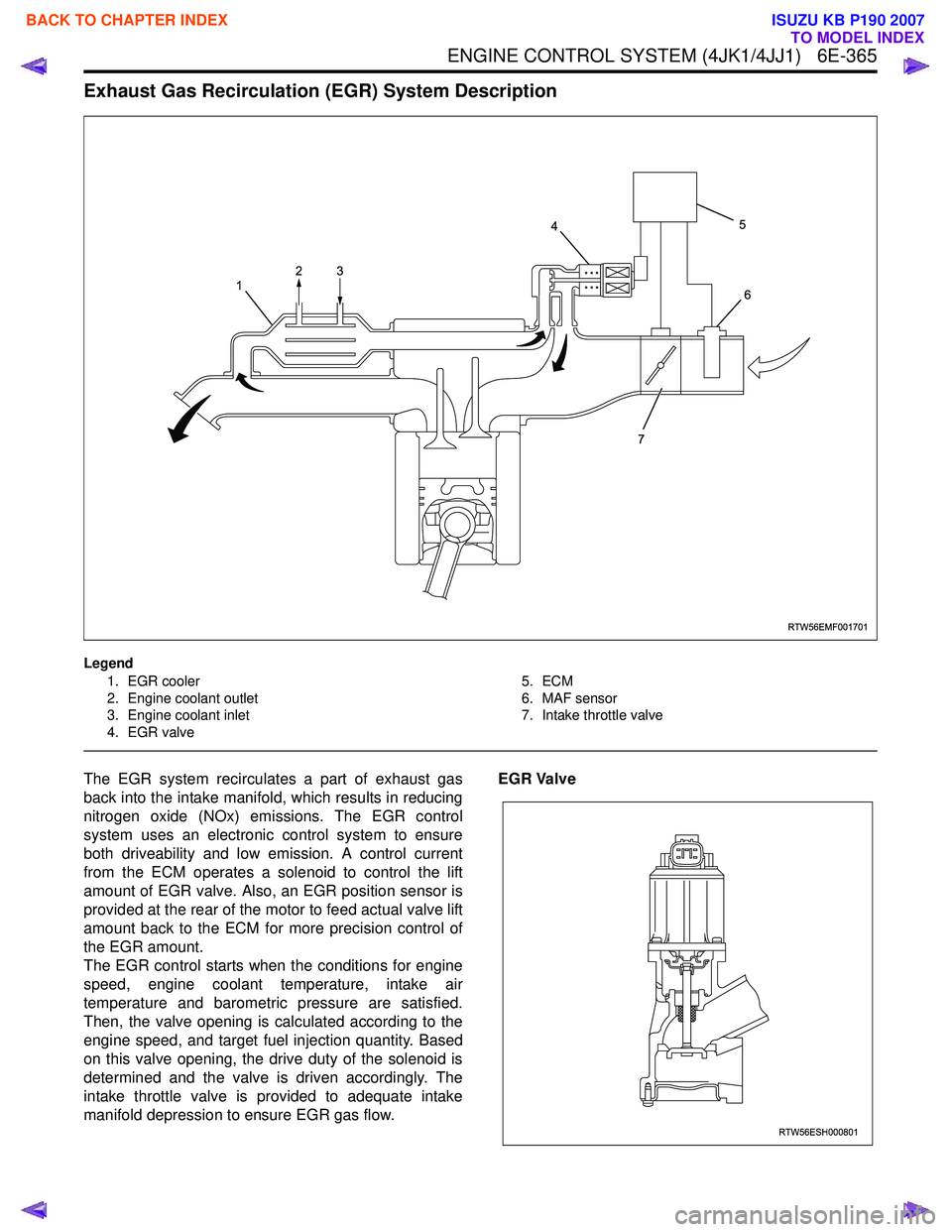
Exhaust Gas Recirculation (EGR) System Description
Legend1. EGR cooler
2. Engine coolant outlet
3. Engine coolant inlet
4. EGR valve 5. ECM
6. MAF sensor
7. Intake throttle valve
The EGR system recirculates a part of exhaust gas
back into the intake manifold, which results in reducing
nitrogen oxide (NOx) emissions. The EGR control
system uses an electronic control system to ensure
both driveability and low emission. A control current
from the ECM operates a solenoid to control the lift
amount of EGR valve. Also, an EGR position sensor is
provided at the rear of the motor to feed actual valve lift
amount back to the ECM for more precision control of
the EGR amount.
The EGR control starts when the conditions for engine
speed, engine coolant temperature, intake air
temperature and barometric pressure are satisfied.
Then, the valve opening is calculated according to the
engine speed, and target fuel injection quantity. Based
on this valve opening, the drive duty of the solenoid is
determined and the valve is driven accordingly. The
intake throttle valve is provided to adequate intake
manifold depression to ensure EGR gas flow. EGR Valve
RTW56EMF001701
1
4
7 5
6
23
RTW56ESH000801
BACK TO CHAPTER INDEX
TO MODEL INDEX
ISUZU KB P190 2007
Page 1983 of 6020
6E-366 ENGINE CONTROL SYSTEM (4JK1/4JJ1)
The EGR valve is mounted on the intake manifold. The
ECM controls the EGR valve opening based on the
engine running condition. The ECM controls the EGR
valve by controlling the solenoid. The solenoid is
controlled based on pulse width modulation (PWM)
signal sent from the ECM. A duty ratio change 0% to
appropriate percentage is EGR valve lift control. To
open the valve, duty ratio is increased. To close the
valve, duty ratio becomes small.
The EGR valve position is detected by the position
sensor, and relayed to the ECM. The position sensor
provides a signal to the ECM on the signal circuit,
which is relative to the position changes of the EGR
valve. The ECM should detect a low signal voltage at a
small lift amount or closed position. The ECM should
detect high signal voltage at a large lift amount.
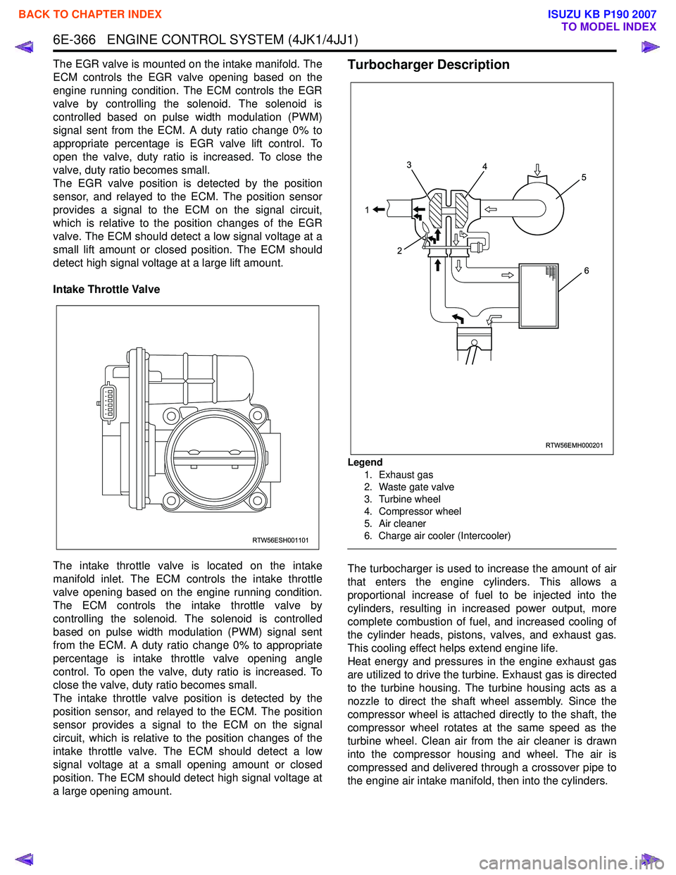
Intake Throttle Valve
The intake throttle valve is located on the intake
manifold inlet. The ECM controls the intake throttle
valve opening based on the engine running condition.
The ECM controls the intake throttle valve by
controlling the solenoid. The solenoid is controlled
based on pulse width modulation (PWM) signal sent
from the ECM. A duty ratio change 0% to appropriate
percentage is intake throttle valve opening angle
control. To open the valve, duty ratio is increased. To
close the valve, duty ratio becomes small.
The intake throttle valve position is detected by the
position sensor, and relayed to the ECM. The position
sensor provides a signal to the ECM on the signal
circuit, which is relative to the position changes of the
intake throttle valve. The ECM should detect a low
signal voltage at a small opening amount or closed
position. The ECM should detect high signal voltage at
a large opening amount.Turbocharger Description
Legend
1. Exhaust gas
2. Waste gate valve
3. Turbine wheel
4. Compressor wheel
5. Air cleaner
6. Charge air cooler (Intercooler)
The turbocharger is used to increase the amount of air
that enters the engine cylinders. This allows a
proportional increase of fuel to be injected into the
cylinders, resulting in increased power output, more
complete combustion of fuel, and increased cooling of
the cylinder heads, pistons, valves, and exhaust gas.
This cooling effect helps extend engine life.
Heat energy and pressures in the engine exhaust gas
are utilized to drive the turbine. Exhaust gas is directed
to the turbine housing. The turbine housing acts as a
nozzle to direct the shaft wheel assembly. Since the
compressor wheel is attached directly to the shaft, the
compressor wheel rotates at the same speed as the
turbine wheel. Clean air from the air cleaner is drawn
into the compressor housing and wheel. The air is
compressed and delivered through a crossover pipe to
the engine air intake manifold, then into the cylinders.
RTW56ESH001101
RTW56EMH000201
1 3
2 4
5
6
BACK TO CHAPTER INDEX
TO MODEL INDEX
ISUZU KB P190 2007
Page 1984 of 6020
ENGINE CONTROL SYSTEM (4JK1/4JJ1) 6E-367
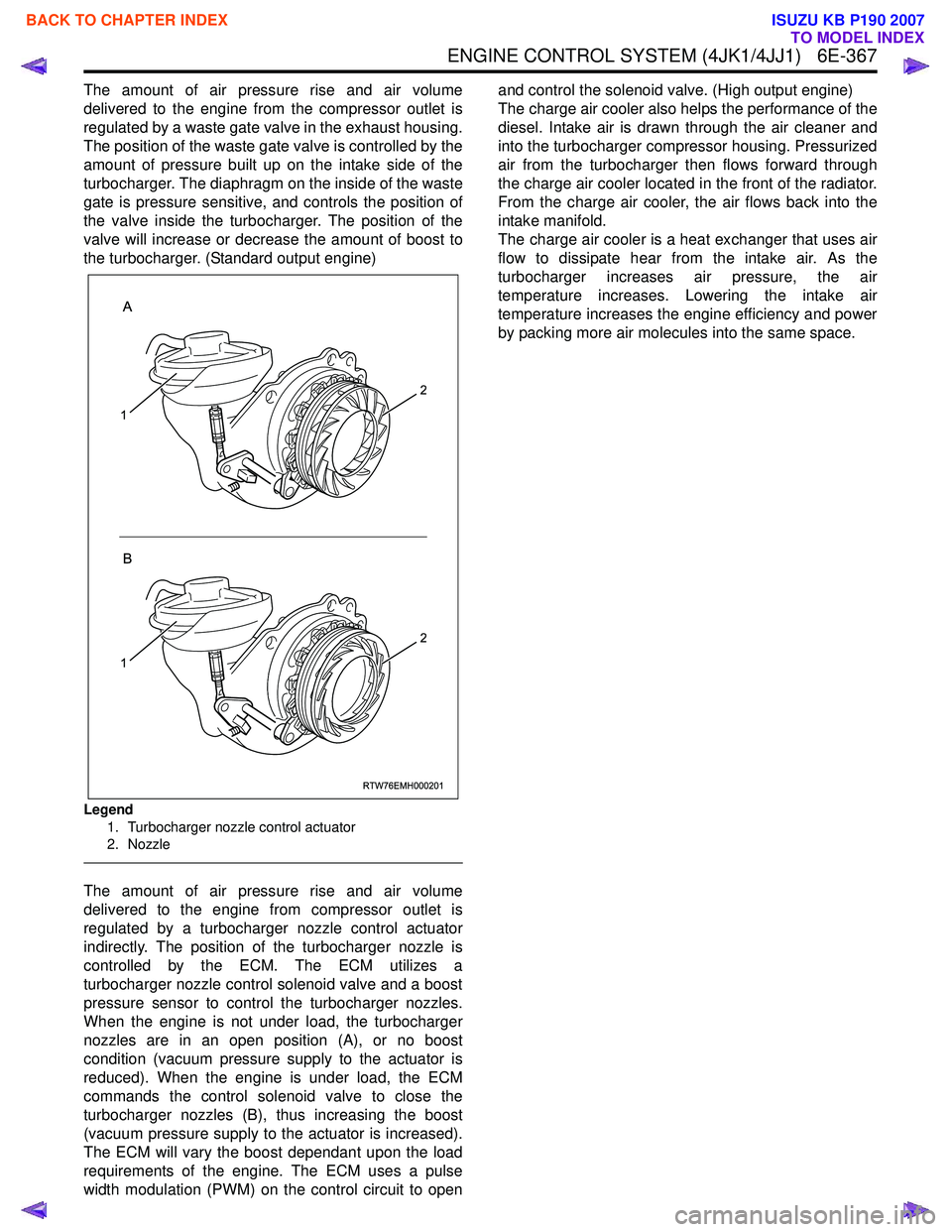
The amount of air pressure rise and air volume
delivered to the engine from the compressor outlet is
regulated by a waste gate valve in the exhaust housing.
The position of the waste gate valve is controlled by the
amount of pressure built up on the intake side of the
turbocharger. The diaphragm on the inside of the waste
gate is pressure sensitive, and controls the position of
the valve inside the turbocharger. The position of the
valve will increase or decrease the amount of boost to
the turbocharger. (Standard output engine)
Legend
1. Turbocharger nozzle control actuator
2. Nozzle
The amount of air pressure rise and air volume
delivered to the engine from compressor outlet is
regulated by a turbocharger nozzle control actuator
indirectly. The position of the turbocharger nozzle is
controlled by the ECM. The ECM utilizes a
turbocharger nozzle control solenoid valve and a boost
pressure sensor to control the turbocharger nozzles.
When the engine is not under load, the turbocharger
nozzles are in an open position (A), or no boost
condition (vacuum pressure supply to the actuator is
reduced). When the engine is under load, the ECM
commands the control solenoid valve to close the
turbocharger nozzles (B), thus increasing the boost
(vacuum pressure supply to the actuator is increased).
The ECM will vary the boost dependant upon the load
requirements of the engine. The ECM uses a pulse
width modulation (PWM) on the control circuit to open and control the solenoid valve. (High output engine)
The charge air cooler also helps the performance of the
diesel. Intake air is drawn through the air cleaner and
into the turbocharger compressor housing. Pressurized
air from the turbocharger then flows forward through
the charge air cooler located in the front of the radiator.
From the charge air cooler, the air flows back into the
intake manifold.
The charge air cooler is a heat exchanger that uses air
flow to dissipate hear from the intake air. As the
turbocharger increases air pressure, the air
temperature increases. Lowering the intake air
temperature increases the engine efficiency and power
by packing more air molecules into the same space.
RTW76EMH000201
A
B
1
2
1
2
BACK TO CHAPTER INDEX
TO MODEL INDEX
ISUZU KB P190 2007
Page 1998 of 6020
ENGINE SPEED CONTROL SYSTEM (4JK1/4JJ1) 6H-1
SECTION 6H
ENGINE SPEED CONTROL SYSTEM
CONTENTS
Accelerator Pedal Position (APP) Sensor ......... 6H-2
Removal .......................................................... 6H-2
Installation ....................................................... 6H-2
How to adjust for APP Sensor......................... 6H-2
BACK TO CHAPTER INDEX
TO MODEL INDEX
ISUZU KB P190 2007
Page 1999 of 6020
6H-2 ENGINE SPEED CONTROL SYSTEM (4JK1/4JJ1)
Accelerator Pedal Position (APP) Sensor
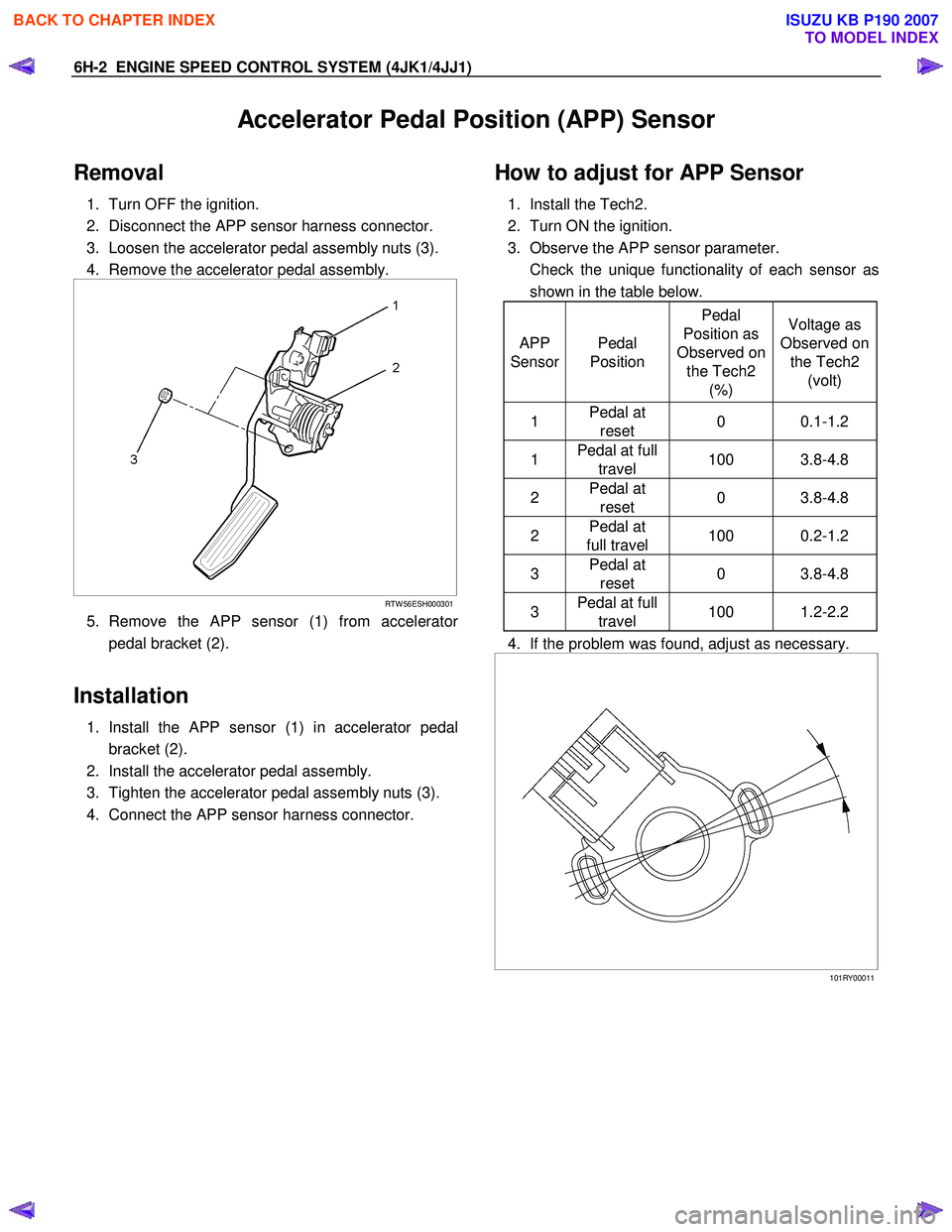
Removal
1. Turn OFF the ignition.
2. Disconnect the APP sensor harness connector.
3. Loosen the accelerator pedal assembly nuts (3).
4. Remove the accelerator pedal assembly.
RTW 56ESH000301
5. Remove the APP sensor (1) from accelerator
pedal bracket (2).
Installation
1. Install the APP sensor (1) in accelerator pedal
bracket (2).
2. Install the accelerator pedal assembly.
3. Tighten the accelerator pedal assembly nuts (3).
4. Connect the APP sensor harness connector.
How to adjust for APP Sensor
1. Install the Tech2.
2. Turn ON the ignition.
3. Observe the APP sensor parameter.
Check the unique functionality of each sensor as shown in the table below.
APP
Sensor Pedal
Position Pedal
Position as
Observed on the Tech2 (%) Voltage as
Observed on the Tech2 (volt)
1 Pedal at
reset 0 0.1-1.2
1 Pedal at full
travel 100 3.8-4.8
2 Pedal at
reset 0 3.8-4.8
2 Pedal at
full travel 100 0.2-1.2
3 Pedal at
reset 0 3.8-4.8
3 Pedal at full
travel 100 1.2-2.2
4. If the problem was found, adjust as necessary.
101RY00011
BACK TO CHAPTER INDEX
TO MODEL INDEX
ISUZU KB P190 2007