Page 952 of 6020

6B – 8 ENGINE COOLING
Draining and Refilling Cooling System
Before draining the cooling system, inspect the system and
perform any necessary service to ensure that it is clean, does
not leak and is in proper working order. The engine coolant
(EC) level should be between the “MIN" and “MAX" lines o
f
reserve tank when the engine is cold. If low, check for leakage
and add EC up to the “MAX" line.
There should not be any excessive deposit of rust or scales
around the radiator cap or radiator filler hole, and the EC
should also be free from oil.
Replace the EC if excessively dirty.
P1010064
1. Completely drain the cooling system by opening the drain
plug at the bottom of the radiator.
2. Remove the radiator cap.
WARNING: To avoid the danger of being burned, do not
remove the cap while the engine and radiator are still hot.
Scalding fluid and steam can be blown out unde
r
pressure.
3. Disconnect all hoses from the EC reserve tank.
Scrub and clean the inside of the reserve tank with soap and water. Flush it well with clean water, then drain it.
Install the reserve tank and hoses.
4. Refill the cooling system with the EC using a solution that is at least 50 percent antifreeze.
Procedure for filling with coolant (in case of full change)
• Make sure that the engine is cool.
• Open radiator cap pour coolant up to filler neck.
• Pour coolant into reservoir tank up to “MAX" line.
• Tighten radiator cap and start the engine. After idling for 2
to 3 minutes, stop the engine and reopen radiator cap. If the
water level is lower, replenish.
WARNING: When the coolant is heated to a high
temperature, be sure not to loosen or remove the radiato
r
cap. Otherwise you might get scalded by not vapor or
boiling water. To open the radiator cap, put a piece of
thick cloth on the cap and loosen the cap slowly to reduce
the pressure when the coolant has become cooler.
BACK TO CHAPTER INDEX
TO MODEL INDEX
ISUZU KB P190 2007
Page 968 of 6020
6C – 4 FUEL SYSTEM
FUEL FILTER AND WATER SEPARATOR
As the inside of the injection pump is lubricated by the fuel which it is pumping, the fuel must be perfectly clean. The
fuel filter and the water separator remove water particles and other foreign material from the fuel before it reaches
the injection pump.
The water separator has an internal float. W hen the float reaches the specified level, a warning light comes on to
remind you to drain the water from the water separator.
A diaphragm type priming pump is installed at the top of the fuel filter. It is used during the air bleeding procedures.
(Except EURO III model)
RTW 36CLF000701
BACK TO CHAPTER INDEX
TO MODEL INDEX
ISUZU KB P190 2007
Page 1047 of 6020
Engine Control System (4JH1) 6E-13
Gauges and Warning Lamps
RTW 76EXF003101
BACK TO CHAPTER INDEX
TO MODEL INDEX
ISUZU KB P190 2007
Page 1522 of 6020

6A-162 ENGINE MECHANICAL (4JK1/4JJ1)
Removal
1. Remove the oil pressure SW .
2. Remove the nipple; oil gallery.
3. Remove the nipple; oil pressure warning SW and gasket.
Inspection
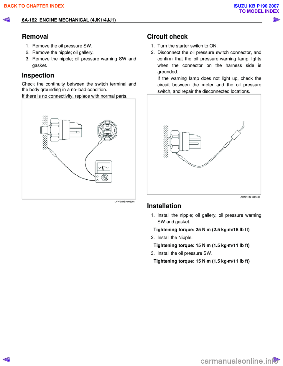
Check the continuity between the switch terminal and
the body grounding in a no-load condition.
If there is no connectivity, replace with normal parts.
LNW 21HSH003301
Circuit check
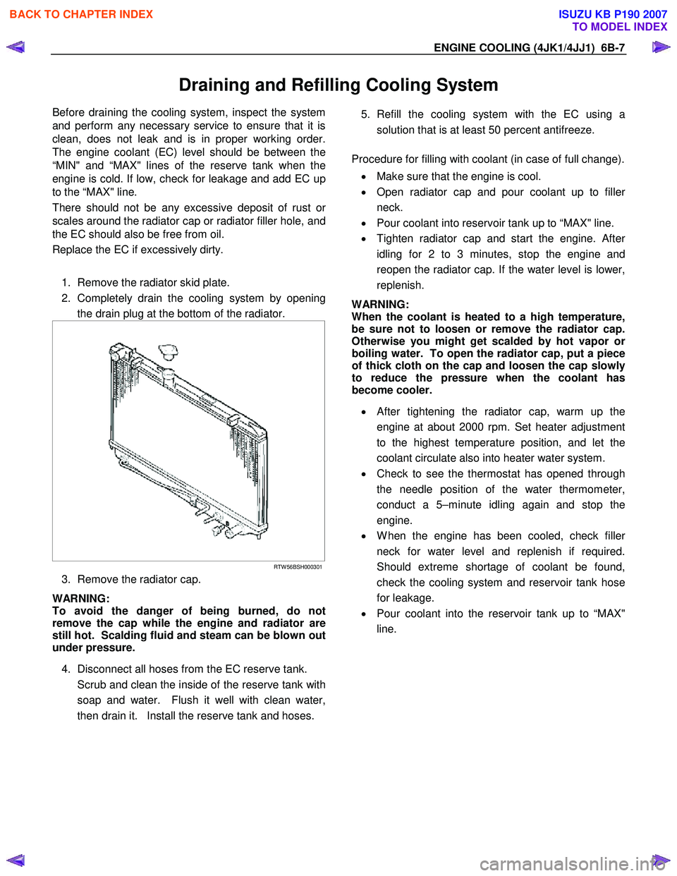
1. Turn the starter switch to ON.
2. Disconnect the oil pressure switch connector, and confirm that the oil pressure-warning lamp lights
when the connector on the harness side is
grounded.
If the warning lamp does not light up, check the circuit between the meter and the oil pressure
switch, and repair the disconnected locations.
LNW 21HSH003401
Installation
1. Install the nipple; oil gallery, oil pressure warning
SW and gasket.
Tightening torque: 25 N ⋅
⋅⋅
⋅
m (2.5 kg ⋅
⋅⋅
⋅
m/18 lb ft)
2. Install the Nipple. Tightening torque: 15 N ⋅
⋅⋅
⋅
m (1.5 kg ⋅
⋅⋅
⋅
m/11 lb ft)
3. Install the oil pressure SW . Tightening torque: 15 N ⋅
⋅⋅
⋅
m (1.5 kg ⋅
⋅⋅
⋅
m/11 lb ft)
BACK TO CHAPTER INDEX
TO MODEL INDEX
ISUZU KB P190 2007
Page 1530 of 6020

ENGINE COOLING (4JK1/4JJ1) 6B-7
Draining and Refilling Cooling System
Before draining the cooling system, inspect the system
and perform any necessary service to ensure that it is
clean, does not leak and is in proper working order.
The engine coolant (EC) level should be between the
“MIN" and “MAX" lines of the reserve tank when the
engine is cold. If low, check for leakage and add EC up
to the “MAX" line.
There should not be any excessive deposit of rust o
r
scales around the radiator cap or radiator filler hole, and
the EC should also be free from oil.
Replace the EC if excessively dirty.
1. Remove the radiator skid plate.
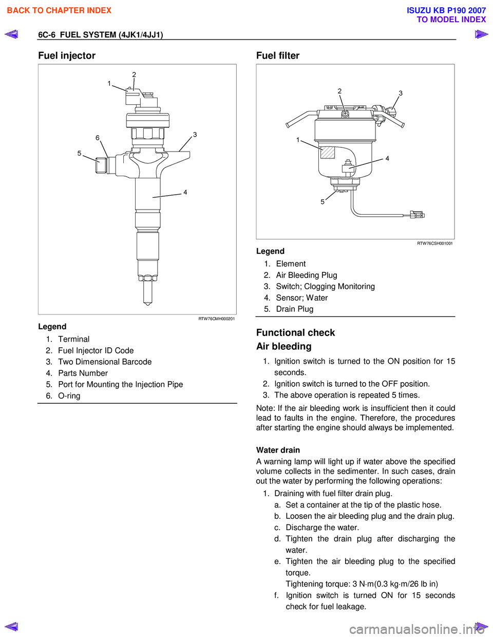
2. Completely drain the cooling system by opening the drain plug at the bottom of the radiator.
RTW 56BSH000301
3. Remove the radiator cap.
WARNING:
To avoid the danger of being burned, do not
remove the cap while the engine and radiator are
still hot. Scalding fluid and steam can be blown out
under pressure.
4. Disconnect all hoses from the EC reserve tank.
Scrub and clean the inside of the reserve tank with soap and water. Flush it well with clean water,
then drain it. Install the reserve tank and hoses.
5. Refill the cooling system with the EC using a
solution that is at least 50 percent antifreeze.
Procedure for filling with coolant (in case of full change).
• Make sure that the engine is cool.
• Open radiator cap and pour coolant up to fille
r
neck.
• Pour coolant into reservoir tank up to “MAX" line.
• Tighten radiator cap and start the engine. Afte
r
idling for 2 to 3 minutes, stop the engine and
reopen the radiator cap. If the water level is lower,
replenish.
WARNING:
When the coolant is heated to a high temperature,
be sure not to loosen or remove the radiator cap.
Otherwise you might get scalded by hot vapor o
r
boiling water. To open the radiator cap, put a piece
of thick cloth on the cap and loosen the cap slowly
to reduce the pressure when the coolant has
become cooler.
• After tightening the radiator cap, warm up the
engine at about 2000 rpm. Set heater adjustment
to the highest temperature position, and let the
coolant circulate also into heater water system.
• Check to see the thermostat has opened through
the needle position of the water thermometer,
conduct a 5–minute idling again and stop the
engine.
• W hen the engine has been cooled, check fille
r
neck for water level and replenish if required.
Should extreme shortage of coolant be found,
check the cooling system and reservoir tank hose
for leakage.
• Pour coolant into the reservoir tank up to “MAX"
line.
BACK TO CHAPTER INDEX
TO MODEL INDEX
ISUZU KB P190 2007
Page 1547 of 6020

6C-6 FUEL SYSTEM (4JK1/4JJ1)
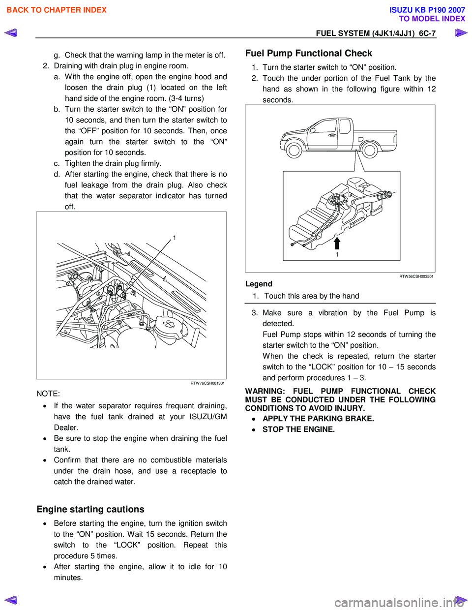
Fuel injector
RTW 76CMH000201
Legend
1. Terminal
2. Fuel Injector ID Code
3. Two Dimensional Barcode
4. Parts Number
5. Port for Mounting the Injection Pipe
6. O-ring
Fuel filter
RTW 76CSH001001
Legend
1. Element
2. Air Bleeding Plug
3. Switch; Clogging Monitoring
4. Sensor; W ater
5. Drain Plug
Functional check
Air bleeding
1. Ignition switch is turned to the ON position for 15 seconds.
2. Ignition switch is turned to the OFF position.
3. The above operation is repeated 5 times.
Note: If the air bleeding work is insufficient then it could
lead to faults in the engine. Therefore, the procedures
after starting the engine should always be implemented.
Water drain
A warning lamp will light up if water above the specified
volume collects in the sedimenter. In such cases, drain
out the water by performing the following operations:
1. Draining with fuel filter drain plug. a. Set a container at the tip of the plastic hose.
b. Loosen the air bleeding plug and the drain plug.
c. Discharge the water.
d. Tighten the drain plug after discharging the water.
e. Tighten the air bleeding plug to the specified torque.
Tightening torque: 3 N ⋅m(0.3 kg ⋅m/26 lb in)
f. Ignition switch is turned ON for 15 seconds check for fuel leakage.
BACK TO CHAPTER INDEX
TO MODEL INDEX
ISUZU KB P190 2007
Page 1548 of 6020

FUEL SYSTEM (4JK1/4JJ1) 6C-7
g. Check that the warning lamp in the meter is off.
2. Draining with drain plug in engine room. a. W ith the engine off, open the engine hood and loosen the drain plug (1) located on the left
hand side of the engine room. (3-4 turns)
b. Turn the starter switch to the “ON” position fo
r
10 seconds, and then turn the starter switch to
the “OFF” position for 10 seconds. Then, once
again turn the starter switch to the “ON”
position for 10 seconds.
c. Tighten the drain plug firmly.
d.
After starting the engine, check that there is no
fuel leakage from the drain plug. Also check
that the water separator indicator has turned
off.
RTW 76CSH001301
NOTE:
• If the water separator requires frequent draining,
have the fuel tank drained at your ISUZU/GM
Dealer.
• Be sure to stop the engine when draining the fuel
tank.
• Confirm that there are no combustible materials
under the drain hose, and use a receptacle to
catch the drained water.
Engine starting cautions
• Before starting the engine, turn the ignition switch
to the “ON” position. W ait 15 seconds. Return the
switch to the “LOCK” position. Repeat this
procedure 5 times.
• After starting the engine, allow it to idle for 10
minutes.
Fuel Pump Functional Check
1. Turn the starter switch to “ON” position.
2. Touch the under portion of the Fuel Tank by the hand as shown in the following figure within 12
seconds.
RTW 56CSH003501
Legend
1. Touch this area by the hand
3. Make sure a vibration by the Fuel Pump is
detected.
Fuel Pump stops within 12 seconds of turning the starter switch to the “ON” position.
W hen the check is repeated, return the starte
r
switch to the “LOCK” position for 10 – 15 seconds
and perform procedures 1 – 3.
WARNING: FUEL PUMP FUNCTIONAL CHECK
MUST BE CONDUCTED UNDER THE FOLLOWING
CONDITIONS TO AVOID INJURY.
•
••
•
APPLY THE PARKING BRAKE.
•
••
•
STOP THE ENGINE.
BACK TO CHAPTER INDEX
TO MODEL INDEX
ISUZU KB P190 2007
Page 1580 of 6020
FUEL SYSTEM (4JK1/4JJ1) 6C-39
Fuel Sedimenter Switch
Inspection
1. Check that there is continuity between the switch
connector terminals when the float in the fuel
sedimenter is above the water drain line.
2. Turn on the ignition switch, remove the fuel sedimenter connector, and connect the terminals
of the connectors on the harness side. Confirm
that the sedimenter warning lamp lights up.
If abnormalities are detected during the check, replace
the switch parts and carry out repairs in case o
f
defective connection between circuits or short circuits.
RTW 76CSH001101
Legend
1. Sensor
2. Connector on The Vehicle Side
3. Harness
4. Drain Valve
BACK TO CHAPTER INDEX
TO MODEL INDEX
ISUZU KB P190 2007