2007 ISUZU KB P190 fuse chart
[x] Cancel search: fuse chartPage 5690 of 6020
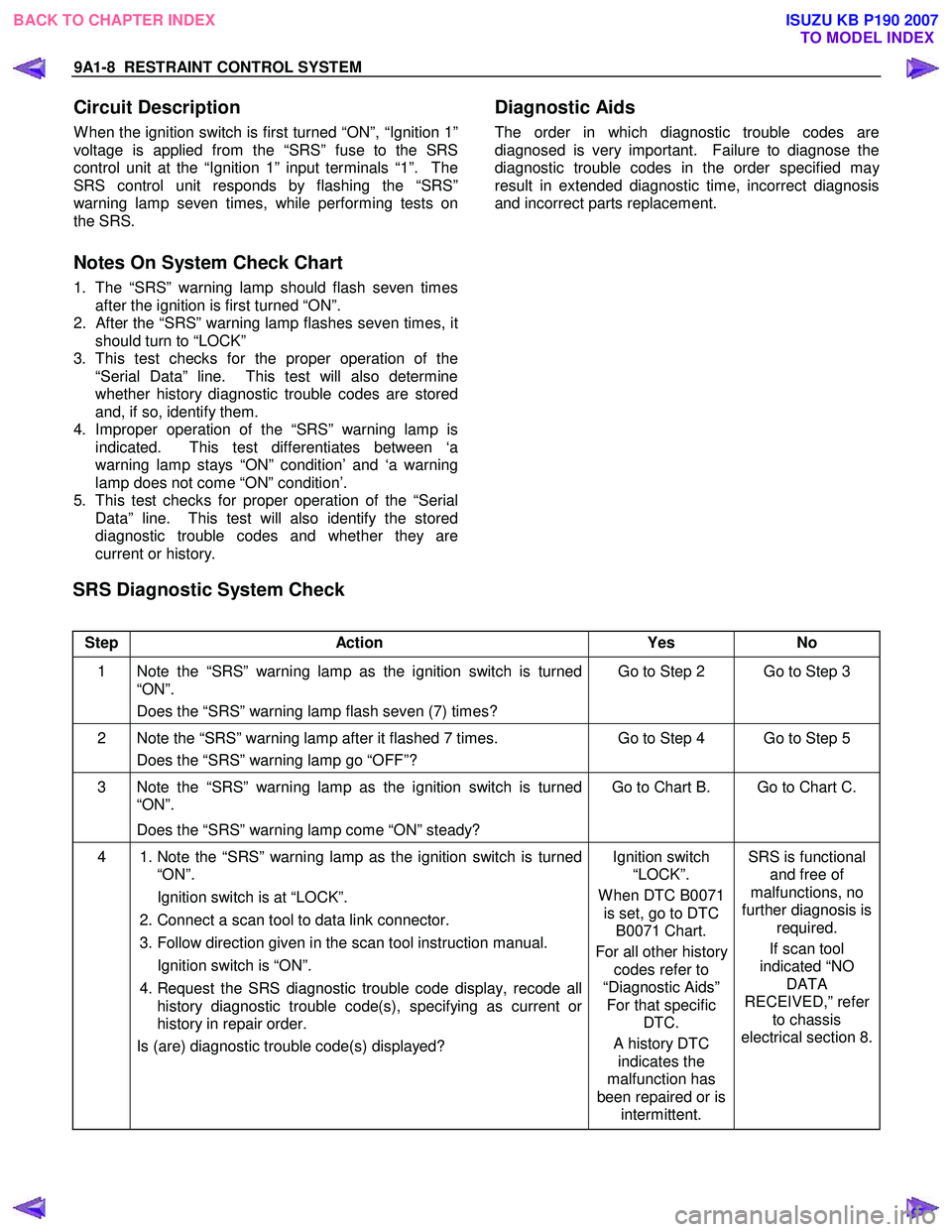
9A1-8 RESTRAINT CONTROL SYSTEM
Circuit Description
W hen the ignition switch is first turned “ON”, “Ignition 1”
voltage is applied from the “SRS” fuse to the SRS
control unit at the “Ignition 1” input terminals “1”. The
SRS control unit responds by flashing the “SRS”
warning lamp seven times, while performing tests on
the SRS.
Notes On System Check Chart
1. The “SRS” warning lamp should flash seven times after the ignition is first turned “ON”.
2.
After the “SRS” warning lamp flashes seven times, it
should turn to “LOCK”
3. This test checks for the proper operation of the “Serial Data” line. This test will also determine
whether history diagnostic trouble codes are stored
and, if so, identify them.
4. Improper operation of the “SRS” warning lamp is indicated. This test differentiates between ‘a
warning lamp stays “ON” condition’ and ‘a warning
lamp does not come “ON” condition’.
5. This test checks for proper operation of the “Serial Data” line. This test will also identify the stored
diagnostic trouble codes and whether they are
current or history.
Diagnostic Aids
The order in which diagnostic trouble codes are
diagnosed is very important. Failure to diagnose the
diagnostic trouble codes in the order specified ma
y
result in extended diagnostic time, incorrect diagnosis
and incorrect parts replacement.
SRS Diagnostic System Check
Step Action Yes No
1 Note the “SRS” warning lamp as the ignition switch is turned
“ON”.
Does the “SRS” warning lamp flash seven (7) times? Go to Step 2 Go to Step 3
2 Note the “SRS” warning lamp after it flashed 7 times.
Does the “SRS” warning lamp go “OFF”? Go to Step 4 Go to Step 5
3 Note the “SRS” warning lamp as the ignition switch is turned
“ON”.
Does the “SRS” warning lamp come “ON” steady? Go to Chart B. Go to Chart C.
4
1. Note the “SRS” warning lamp as the ignition switch is turned
“ON”.
Ignition switch is at “LOCK”.
2. Connect a scan tool to data link connector.
3. Follow direction given in the scan tool instruction manual.
Ignition switch is “ON”.
4. Request the SRS diagnostic trouble code display, recode all
history diagnostic trouble code(s), specifying as current or
history in repair order.
Is (are) diagnostic trouble code(s) displayed?
Ignition switch
“LOCK”.
W hen DTC B0071 is set, go to DTC B0071 Chart.
For all other history codes refer to
“Diagnostic Aids” For that specific DTC.
A history DTC indicates the
malfunction has
been repaired or is intermittent. SRS is functional
and free of
malfunctions, no
further diagnosis is required.
If scan tool
indicated “NO DATA
RECEIVED,” refer to chassis
electrical section 8.
BACK TO CHAPTER INDEX TO MODEL INDEX
ISUZU KB P190 2007
Page 5694 of 6020
9A1-12 RESTRAINT CONTROL SYSTEM
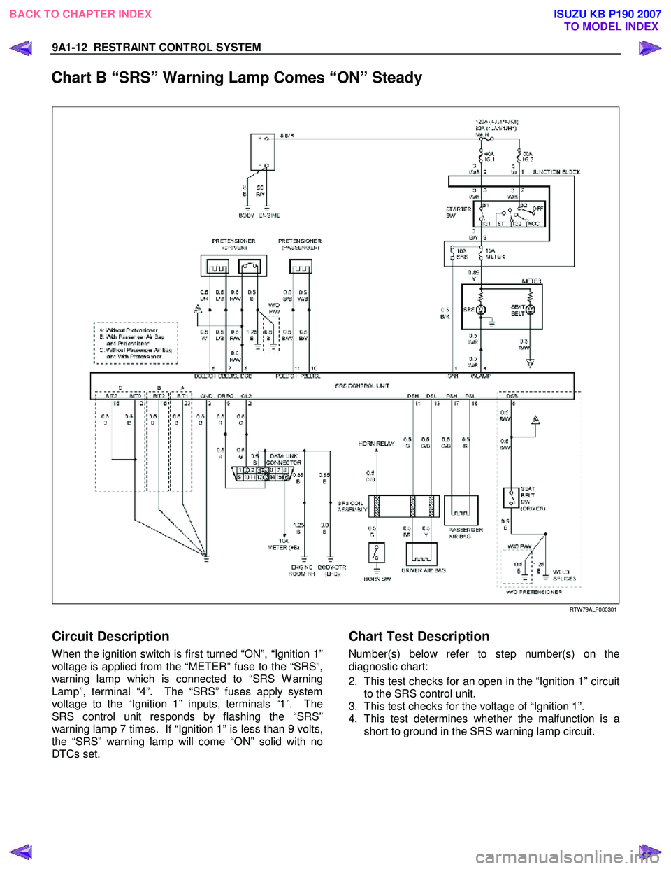
Chart B “SRS” Warning Lamp Comes “ON” Steady
RTW 79ALF000301
Circuit Description
W hen the ignition switch is first turned “ON”, “Ignition 1”
voltage is applied from the “METER” fuse to the “SRS”,
warning lamp which is connected to “SRS W arning
Lamp”, terminal “4”. The “SRS” fuses apply system
voltage to the “Ignition 1” inputs, terminals “1”. The
SRS control unit responds by flashing the “SRS”
warning lamp 7 times. If “Ignition 1” is less than 9 volts,
the “SRS” warning lamp will come “ON” solid with no
DTCs set.
Chart Test Description
Number(s) below refer to step number(s) on the
diagnostic chart:
2. This test checks for an open in the “Ignition 1” circuit to the SRS control unit.
3. This test checks for the voltage of “Ignition 1”.
4. This test determines whether the malfunction is a short to ground in the SRS warning lamp circuit.
BACK TO CHAPTER INDEX TO MODEL INDEX
ISUZU KB P190 2007
Page 5696 of 6020
9A1-14 RESTRAINT CONTROL SYSTEM
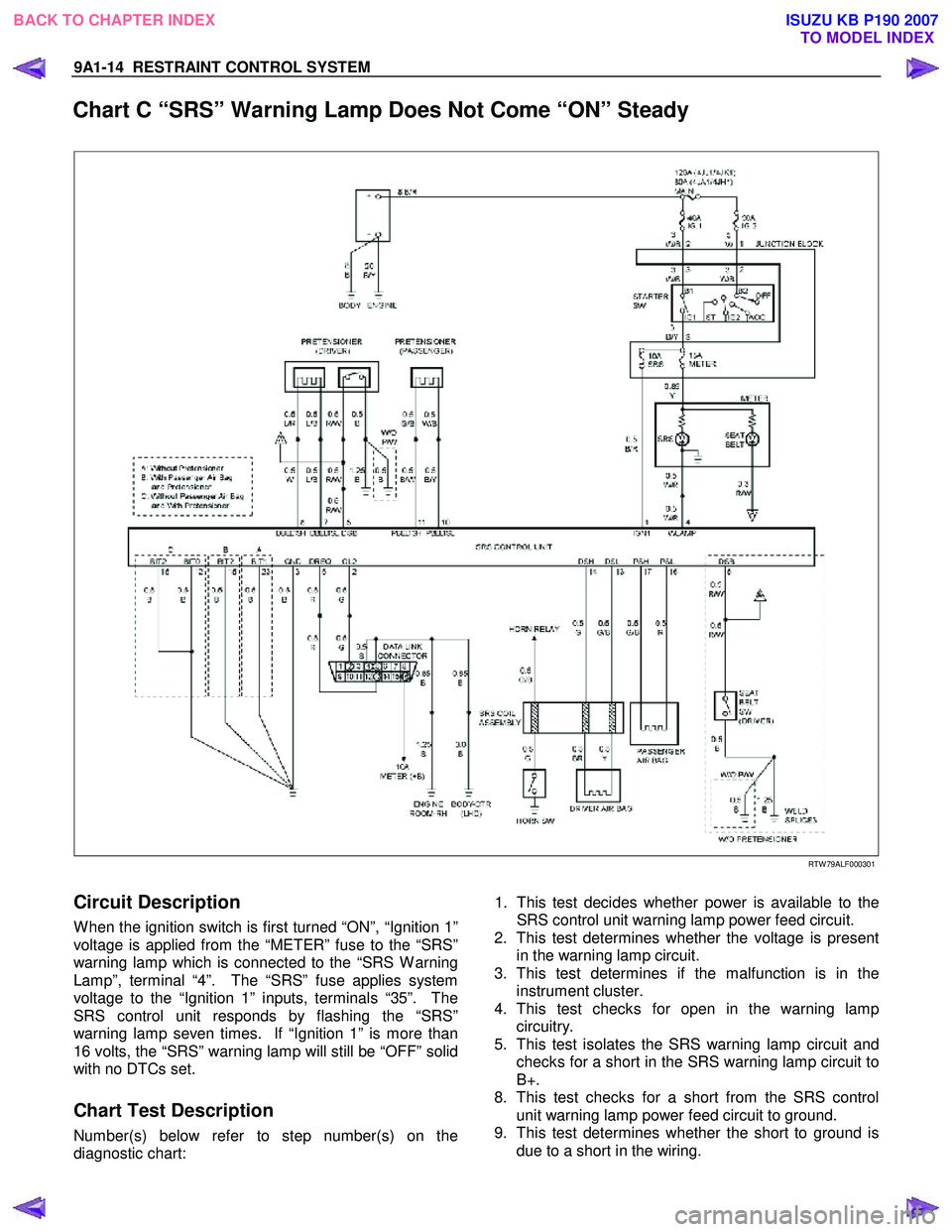
Chart C “SRS” Warning Lamp Does Not Come “ON” Steady
RTW 79ALF000301
Circuit Description
W hen the ignition switch is first turned “ON”, “Ignition 1”
voltage is applied from the “METER” fuse to the “SRS”
warning lamp which is connected to the “SRS W arning
Lamp”, terminal “4”. The “SRS” fuse applies system
voltage to the “Ignition 1” inputs, terminals “35”. The
SRS control unit responds by flashing the “SRS”
warning lamp seven times. If “Ignition 1” is more than
16 volts, the “SRS” warning lamp will still be “OFF” solid
with no DTCs set.
Chart Test Description
Number(s) below refer to step number(s) on the
diagnostic chart:
1. This test decides whether power is available to the
SRS control unit warning lamp power feed circuit.
2. This test determines whether the voltage is present
in the warning lamp circuit.
3. This test determines if the malfunction is in the
instrument cluster.
4. This test checks for open in the warning lamp
circuitry.
5. This test isolates the SRS warning lamp circuit and
checks for a short in the SRS warning lamp circuit to
B+.
8. This test checks for a short from the SRS control
unit warning lamp power feed circuit to ground.
9. This test determines whether the short to ground is
due to a short in the wiring.
BACK TO CHAPTER INDEX TO MODEL INDEX
ISUZU KB P190 2007
Page 5697 of 6020
RESTRAINT CONTROL SYSTEM 9A1-15
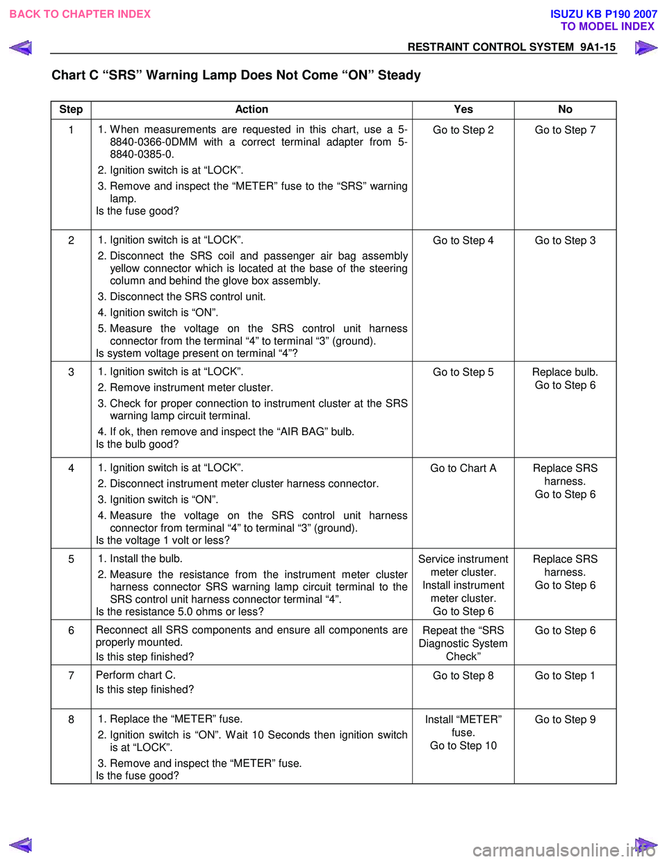
Chart C “SRS” Warning Lamp Does Not Come “ON” Steady
Step Action Yes No
1
1. W hen measurements are requested in this chart, use a 5-
8840-0366-0DMM with a correct terminal adapter from 5-
8840-0385-0.
2. Ignition switch is at “LOCK”.
3. Remove and inspect the “METER” fuse to the “SRS” warning lamp.
Is the fuse good? Go to Step 2 Go to Step 7
2
1. Ignition switch is at “LOCK”.
2. Disconnect the SRS coil and passenger air bag assembly
yellow connector which is located at the base of the steering
column and behind the glove box assembly.
3. Disconnect the SRS control unit.
4. Ignition switch is “ON”.
5. Measure the voltage on the SRS control unit harness connector from the terminal “4” to terminal “3” (ground).
Is system voltage present on terminal “4”? Go to Step 4 Go to Step 3
3
1. Ignition switch is at “LOCK”.
2. Remove instrument meter cluster.
3. Check for proper connection to instrument cluster at the SRS warning lamp circuit terminal.
4. If ok, then remove and inspect the “AIR BAG” bulb.
Is the bulb good? Go to Step 5 Replace bulb.
Go to Step 6
4
1. Ignition switch is at “LOCK”.
2. Disconnect instrument meter cluster harness connector.
3. Ignition switch is “ON”.
4. Measure the voltage on the SRS control unit harness
connector from terminal “4” to terminal “3” (ground).
Is the voltage 1 volt or less? Go to Chart A Replace SRS
harness.
Go to Step 6
5
1. Install the bulb.
2. Measure the resistance from the instrument meter cluster
harness connector SRS warning lamp circuit terminal to the
SRS control unit harness connector terminal “4”.
Is the resistance 5.0 ohms or less? Service instrument
meter cluster.
Install instrument meter cluster. Go to Step 6 Replace SRS
harness.
Go to Step 6
6 Reconnect all SRS components and ensure all components are
properly mounted.
Is this step finished? Repeat the “SRS
Diagnostic System Check” Go to Step 6
7
Perform chart C.
Is this step finished? Go to Step 8 Go to Step 1
8
1. Replace the “METER” fuse.
2. Ignition switch is “ON”. W ait 10 Seconds then ignition switch
is at “LOCK”.
3. Remove and inspect the “METER” fuse.
Is the fuse good? Install “METER”
fuse.
Go to Step 10 Go to Step 9
BACK TO CHAPTER INDEX
TO MODEL INDEX
ISUZU KB P190 2007
Page 5698 of 6020
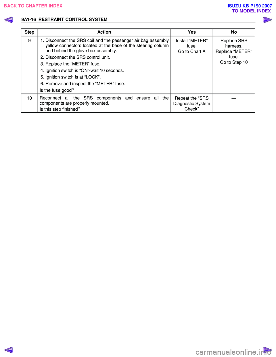
9A1-16 RESTRAINT CONTROL SYSTEM
Step Action Yes No
9
1. Disconnect the SRS coil and the passenger air bag assembly
yellow connectors located at the base of the steering column
and behind the glove box assembly.
2. Disconnect the SRS control unit.
3. Replace the “METER” fuse.
4. Ignition switch is “ON”-wait 10 seconds.
5. Ignition switch is at “LOCK”.
6. Remove and inspect the “METER” fuse.
Is the fuse good? Install “METER”
fuse.
Go to Chart A Replace SRS
harness.
Replace “METER” fuse.
Go to Step 10
10 Reconnect all the SRS components and ensure all the
components are properly mounted.
Is this step finished? Repeat the “SRS
Diagnostic System Check” —
BACK TO CHAPTER INDEX
TO MODEL INDEX
ISUZU KB P190 2007
Page 5751 of 6020
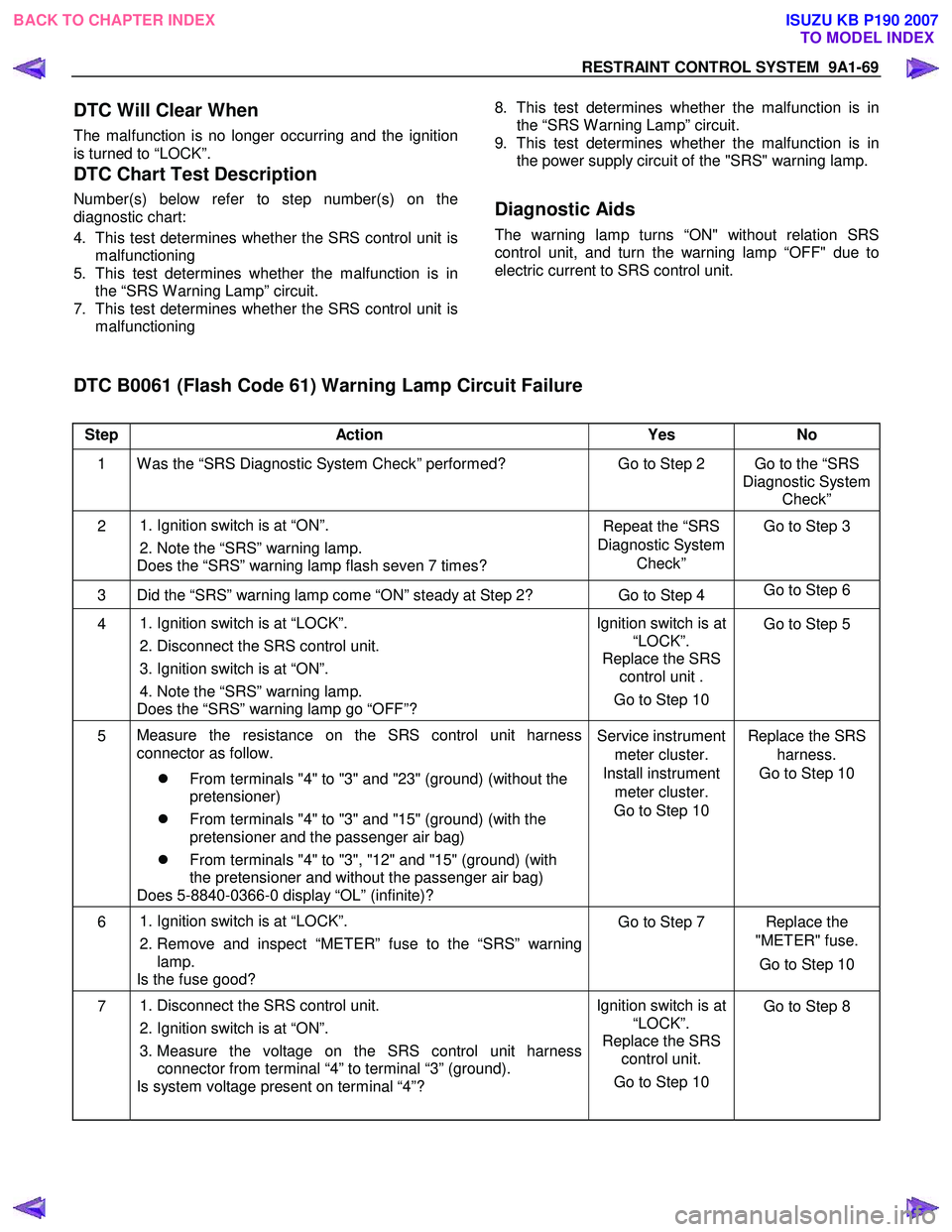
RESTRAINT CONTROL SYSTEM 9A1-69
DTC Will Clear When
The malfunction is no longer occurring and the ignition
is turned to “LOCK”.
DTC Chart Test Description
Number(s) below refer to step number(s) on the
diagnostic chart:
4. This test determines whether the SRS control unit is malfunctioning
5. This test determines whether the malfunction is in the “SRS W arning Lamp” circuit.
7. This test determines whether the SRS control unit is malfunctioning
8. This test determines whether the malfunction is in
the “SRS W arning Lamp” circuit.
9. This test determines whether the malfunction is in the power supply circuit of the "SRS" warning lamp.
Diagnostic Aids
The warning lamp turns “ON" without relation SRS
control unit, and turn the warning lamp “OFF" due to
electric current to SRS control unit.
DTC B0061 (Flash Code 61) Warning Lamp Circuit Failure
Step Action Yes No
1 W as the “SRS Diagnostic System Check” performed? Go to Step 2 Go to the “SRS
Diagnostic System Check”
2
1. Ignition switch is at “ON”.
2. Note the “SRS” warning lamp.
Does the “SRS” warning lamp flash seven 7 times? Repeat the “SRS
Diagnostic System Check” Go to Step 3
3 Did the “SRS” warning lamp come “ON” steady at Step 2? Go to Step 4
Go to Step 6
4
1. Ignition switch is at “LOCK”.
2. Disconnect the SRS control unit.
3. Ignition switch is at “ON”.
4. Note the “SRS” warning lamp.
Does the “SRS” warning lamp go “OFF”? Ignition switch is at
“LOCK”.
Replace the SRS control unit .
Go to Step 10 Go to Step 5
5
Measure the resistance on the SRS control unit harness
connector as follow.
�z From terminals "4" to "3" and "23" (ground) (without the
pretensioner)
�z From terminals "4" to "3" and "15" (ground) (with the
pretensioner and the passenger air bag)
�z From terminals "4" to "3", "12" and "15" (ground) (with
the pretensioner and without the passenger air bag)
Does 5-8840-0366-0 display “OL” (infinite)? Service instrument
meter cluster.
Install instrument meter cluster.
Go to Step 10 Replace the SRS
harness.
Go to Step 10
6
1. Ignition switch is at “LOCK”.
2. Remove and inspect “METER” fuse to the “SRS” warning lamp.
Is the fuse good? Go to Step 7 Replace the
"METER" fuse.
Go to Step 10
7 1. Disconnect the SRS control unit.
2. Ignition switch is at “ON”.
3. Measure the voltage on the SRS control unit harness connector from terminal “4” to terminal “3” (ground).
Is system voltage present on terminal “4”? Ignition switch is at
“LOCK”.
Replace the SRS control unit.
Go to Step 10
Go to Step 8
BACK TO CHAPTER INDEX
TO MODEL INDEX
ISUZU KB P190 2007
Page 5860 of 6020
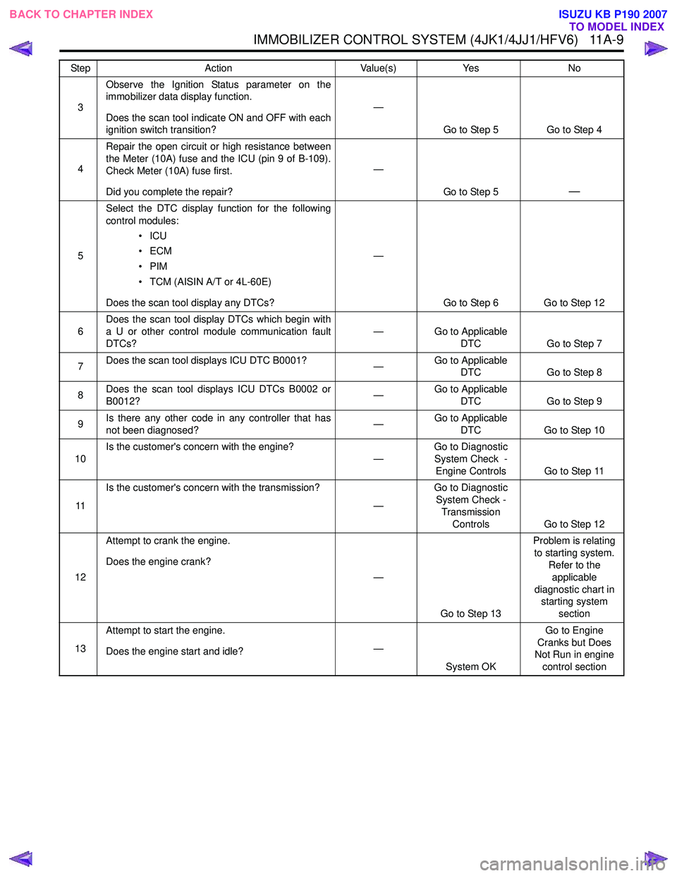
IMMOBILIZER CONTROL SYSTEM (4JK1/4JJ1/HFV6) 11A-9
3Observe the Ignition Status parameter on the
immobilizer data display function.
Does the scan tool indicate ON and OFF with each
ignition switch transition? —
Go to Step 5 Go to Step 4
4 Repair the open circuit or high resistance between
the Meter (10A) fuse and the ICU (pin 9 of B-109).
Check Meter (10A) fuse first.
Did you complete the repair? —
Go to Step 5
—
5Select the DTC display function for the following
control modules:
•ICU
•ECM
•PIM
• TCM (AISIN A/T or 4L-60E)
Does the scan tool display any DTCs? —
Go to Step 6 Go to Step 12
6 Does the scan tool display DTCs which begin with
a U or other control module communication fault
DTCs? —
Go to Applicable
DTC Go to Step 7
7 Does the scan tool displays ICU DTC B0001?
—Go to Applicable
DTC Go to Step 8
8 Does the scan tool displays ICU DTCs B0002 or
B0012? —Go to Applicable
DTC Go to Step 9
9 Is there any other code in any controller that has
not been diagnosed? —Go to Applicable
DTC Go to Step 10
10 Is the customer's concern with the engine?
—Go to Diagnostic
System Check -
Engine Controls Go to Step 11
11 Is the customer's concern with the transmission?
—Go to Diagnostic
System Check - Transmission
Controls Go to Step 12
12 Attempt to crank the engine.
Does the engine crank? —
Go to Step 13 Problem is relating
to starting system. Refer to the
applicable
diagnostic chart in starting system
section
13 Attempt to start the engine.
Does the engine start and idle? —
System OK Go to Engine
Cranks but Does
Not Run in engine
control section
Step
Action Value(s)Yes No
BACK TO CHAPTER INDEX
TO MODEL INDEX
ISUZU KB P190 2007
Page 5863 of 6020
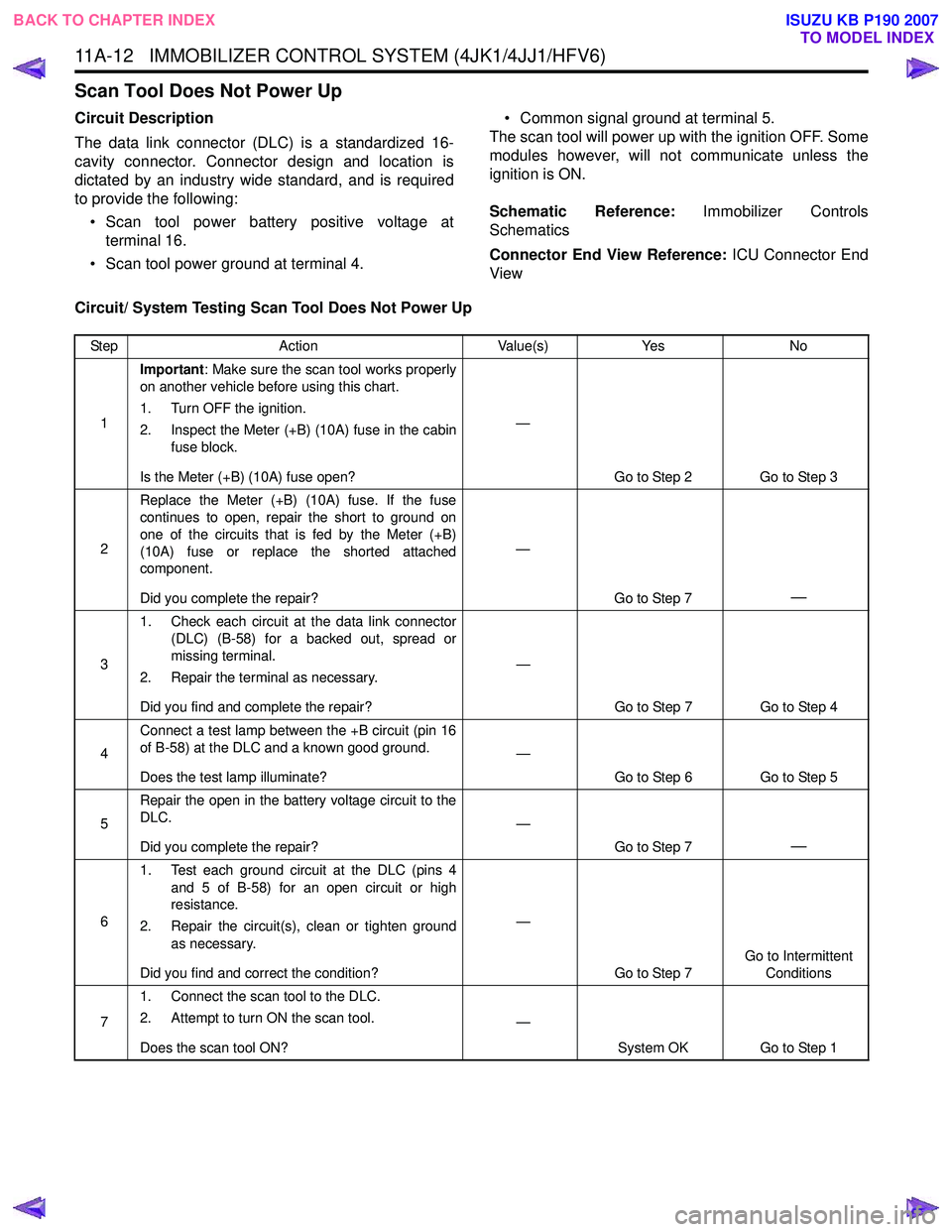
11A-12 IMMOBILIZER CONTROL SYSTEM (4JK1/4JJ1/HFV6)
Scan Tool Does Not Power Up
Circuit Description
The data link connector (DLC) is a standardized 16-
cavity connector. Connector design and location is
dictated by an industry wide standard, and is required
to provide the following:
• Scan tool power battery positive voltage at terminal 16.
• Scan tool power ground at terminal 4. • Common signal ground at terminal 5.
The scan tool will power up with the ignition OFF. Some
modules however, will not communicate unless the
ignition is ON.
Schematic Reference: Immobilizer Controls
Schematics
Connector End View Reference: ICU Connector End
View
Circuit/ System Testing Scan Tool Does Not Power Up
Step Action Value(s)Yes No
1 Important
: Make sure the scan tool works properly
on another vehicle before using this chart.
1. Turn OFF the ignition.
2. Inspect the Meter (+B) (10A) fuse in the cabin fuse block.
Is the Meter (+B) (10A) fuse open? —
Go to Step 2 Go to Step 3
2 Replace the Meter (+B) (10A) fuse. If the fuse
continues to open, repair the short to ground on
one of the circuits that is fed by the Meter (+B)
(10A) fuse or replace the shorted attached
component.
Did you complete the repair? —
Go to Step 7
—
31. Check each circuit at the data link connector
(DLC) (B-58) for a backed out, spread or
missing terminal.
2. Repair the terminal as necessary.
Did you find and complete the repair? —
Go to Step 7 Go to Step 4
4 Connect a test lamp between the +B circuit (pin 16
of B-58) at the DLC and a known good ground.
Does the test lamp illuminate? —
Go to Step 6 Go to Step 5
5 Repair the open in the battery voltage circuit to the
DLC.
Did you complete the repair? —
Go to Step 7
—
61. Test each ground circuit at the DLC (pins 4
and 5 of B-58) for an open circuit or high
resistance.
2. Repair the circuit(s), clean or tighten ground as necessary.
Did you find and correct the condition? —
Go to Step 7 Go to Intermittent
Conditions
7 1. Connect the scan tool to the DLC.
2. Attempt to turn ON the scan tool.
Does the scan tool ON? —
System OK Go to Step 1
BACK TO CHAPTER INDEX
TO MODEL INDEX
ISUZU KB P190 2007