2007 ISUZU KB P190 fuse chart
[x] Cancel search: fuse chartPage 3421 of 6020
Engine Management – V6 – Diagnostics Page 6C1-2–143
• To assist diagnosis, refer to 3 W iring Diagrams and Connector Charts in this Section, for the system wiring
diagram and connector charts.
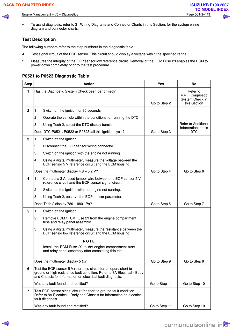
Test Description
The following numbers refer to the step numbers in the diagnostic table:
4 Test signal circuit of the EOP sensor. This circuit should display a voltage within the specified range.
5 Measures the integrity of the EOP sensor low reference circuit. Removal of the ECM Fuse 29 enables the ECM to power down completely prior to the test procedure.
P0521 to P0523 Diagnostic Table
Step Action Yes No
1 Has the Diagnostic System Check been performed?
Go to Step 2 Refer to
4.4 Diagnostic
System Check in this Section
2 1 Switch off the ignition for 30 seconds.
2 Operate the vehicle within the conditions for running the DTC.
3 Using Tech 2, select the DTC display function.
Does DTC P0521, P0522 or P0523 fail this ignition cycle? Go to Step 3 Refer to Additional
Information in this DTC
3 1 Switch off the ignition.
2 Disconnect the EOP sensor wiring connector.
3 Switch on the ignition with the engine not running.
4 Using a digital multimeter, measure the voltage between the EOP sensor 5 V reference circuit and the ECM housing.
Does the multimeter display 4.8 – 5.2 V? Go to Step 4 Go to Step 6
4 1 Connect a 3 A fused jumper wire between the EOP sensor 5 V
reference circuit and the EOP sensor signal circuit.
2 Switch on the ignition with the engine not running.
3 Using Tech 2, observe the EOP sensor parameter.
Does Tech 2 display 780 – 980 kPa? Go to Step 5 Go to Step 7
5 1 Switch off the ignition.
2 Remove ECM / TCM Fuse 29 from the engine compartment fuse and relay panel assembly.
3 Using a digital multimeter, measure the resistance between the EOP sensor low reference circuit and the ECM housing.
NOTE
Install the ECM Fuse 29 to the engine compartment fuse
and relay panel assembly after completing this test.
Does the multimeter display 5 Ω? Go to Step 9 Go to Step 8
6 Test the EOP sensor 5 V reference circuit for an open, short to
ground or high resistance fault condition. Refer to 8A Electrical - Body
and Chassis for information on electrical fault diagnosis.
W as any fault found and rectified? Go to Step 11 Go to Step 10
7 Test EOP sensor signal circuit for short to ground fault condition.
Refer to 8A Electrical - Body and Chassis for information on electrical
fault diagnosis.
W as any fault found and rectified? Go to Step 11 Go to Step 10
BACK TO CHAPTER INDEX
TO MODEL INDEX
ISUZU KB P190 2007
Page 3423 of 6020
Engine Management – V6 – Diagnostics Page 6C1-2–145
An A/C refrigerant pressure sensor circuit DTC sets if the ECM detects the A/C pressure sensor signal is not within the
specified range for 3 seconds.
Conditions for Running the DTC
DTC P0532 and P0533 run continuously when the engine is running or when the A/C is switched on.
Conditions for Setting the DTC
DTC P0532
The A/C refrigerant pressure signal voltage is less than 0.2 V for longer than 3 seconds.
DTC P0533
The A/C refrigerant pressure signal voltage is greater than 4.9 V for longer than 3 seconds.
Conditions for Clearing the DTC
The A/C refrigerant pressure sensor circuit DTCs are Type C DTCs. Refer to 1.4 Diagnostic Trouble Codes in this
Section, for action taken when Type C DTC sets and conditions for clearing Type C DTCs.
Additional Information
• Refer to 6C1-1 Engine Management – V6 – General Information for details of the A/C Refrigerant Pressure Sensor
operation.
• For an intermittent fault condition, refer to 5.2 Intermittent Fault Conditions in this Section.
• The A/C refrigerant pressure sensor circuit diagnostic table is developed with the assumption the A/C refrigerant
system is functioning correctly. Therefore, rectify any A/C refrigerant system fault conditions before proceeding
with this diagnostic procedure.
− An A/C refrigerant low-pressure fault condition may cause DTC P0532 to set.
− An A/C refrigerant high-pressure fault condition may cause DTC P0533 to set.
• Since fault condition in a wiring connector may trigger DTCs, always test the connectors related to this diagnostic
procedure for shorted terminals or poor wiring connection before replacing any component. Refer to 8A Electrical -
Body and Chassis for information on electrical fault diagnosis.
• To assist diagnosis, refer to 3 W iring Diagrams and Connector Charts in this Section, for the system wiring
diagram and connector charts.
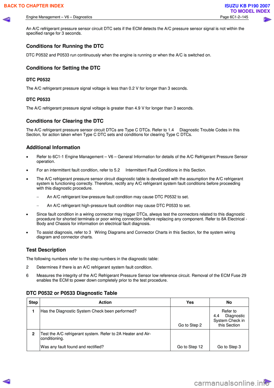
Test Description
The following numbers refer to the step numbers in the diagnostic table:
2 Determines if there is an A/C refrigerant system fault condition.
6 Measures the integrity of the A/C Refrigerant Pressure Sensor low reference circuit. Removal of the ECM Fuse 29 enables the ECM to power down completely prior to the test procedure.
DTC P0532 or P0533 Diagnostic Table
Step Action Yes No
1 Has the Diagnostic System Check been performed?
Go to Step 2 Refer to
4.4 Diagnostic
System Check in this Section
2 Test the A/C refrigerant system. Refer to 2A Heater and Air-
conditioning.
W as any fault found and rectified? Go to Step 12 Go to Step 3
BACK TO CHAPTER INDEX
TO MODEL INDEX
ISUZU KB P190 2007
Page 3426 of 6020
Engine Management – V6 – Diagnostics Page 6C1-2–148
Conditions for Clearing the DTC
The ECM system voltage DTCs are Type C DTCs. Refer to 1.4 Diagnostic Trouble Codes in this Section, for action
taken when a Type C DTC sets and conditions for clearing Type C DTCs.
Additional Information
• For an intermittent fault condition, refer to 5.2 Intermittent Fault Conditions in this Section.
• Refer to 6C1-1 Engine Management – V6 – General Information for details of the ECM operation.
• Since fault condition in a wiring connector may trigger DTCs, always test the connectors related to this diagnostic
procedure for shorted terminals or poor wiring connection before replacing any component. Refer to 8A Electrical -
Body and Chassis for information on electrical fault diagnosis.
• To assist diagnosis, refer to 3 W iring Diagrams and Connector Charts in this Section, for the system wiring
diagram and connector charts.
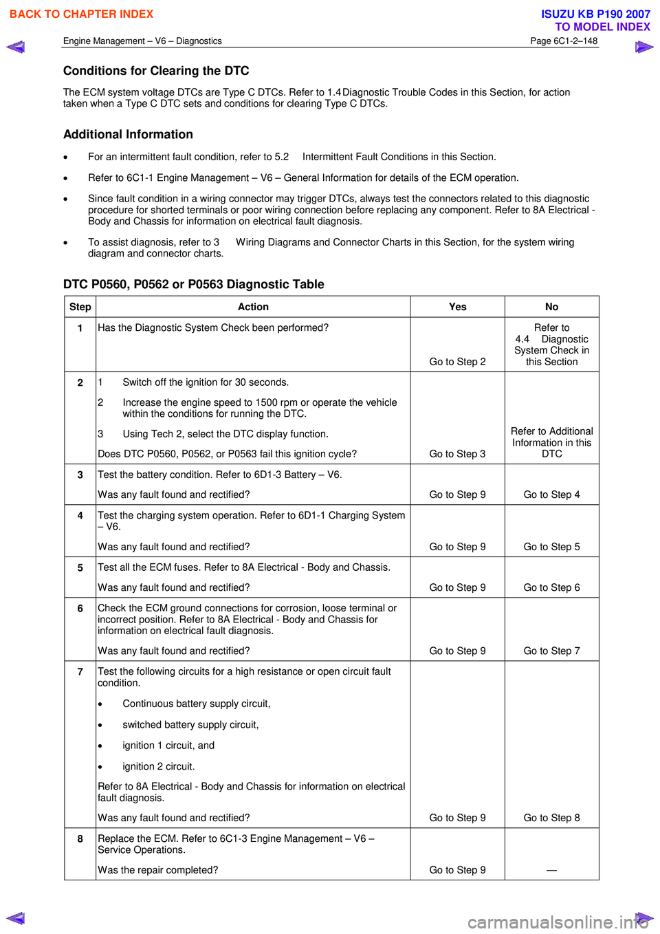
DTC P0560, P0562 or P0563 Diagnostic Table
Step Action Yes No
1 Has the Diagnostic System Check been performed?
Go to Step 2 Refer to
4.4 Diagnostic
System Check in this Section
2 1 Switch off the ignition for 30 seconds.
2 Increase the engine speed to 1500 rpm or operate the vehicle within the conditions for running the DTC.
3 Using Tech 2, select the DTC display function.
Does DTC P0560, P0562, or P0563 fail this ignition cycle? Go to Step 3 Refer to Additional
Information in this DTC
3 Test the battery condition. Refer to 6D1-3 Battery – V6.
W as any fault found and rectified? Go to Step 9 Go to Step 4
4 Test the charging system operation. Refer to 6D1-1 Charging System
– V6.
W as any fault found and rectified? Go to Step 9 Go to Step 5
5 Test all the ECM fuses. Refer to 8A Electrical - Body and Chassis.
W as any fault found and rectified? Go to Step 9 Go to Step 6
6 Check the ECM ground connections for corrosion, loose terminal or
incorrect position. Refer to 8A Electrical - Body and Chassis for
information on electrical fault diagnosis.
W as any fault found and rectified? Go to Step 9 Go to Step 7
7 Test the following circuits for a high resistance or open circuit fault
condition.
• Continuous battery supply circuit,
• switched battery supply circuit,
• ignition 1 circuit, and
• ignition 2 circuit.
Refer to 8A Electrical - Body and Chassis for information on electrical
fault diagnosis.
W as any fault found and rectified? Go to Step 9 Go to Step 8
8 Replace the ECM. Refer to 6C1-3 Engine Management – V6 –
Service Operations.
W as the repair completed? Go to Step 9 —
BACK TO CHAPTER INDEX
TO MODEL INDEX
ISUZU KB P190 2007
Page 3428 of 6020
Engine Management – V6 – Diagnostics Page 6C1-2–150
DTC P0606
There is an internal ECM circuit fault condition for 6 seconds.
Conditions for Clearing the DTC
The ECM Internal Circuit, Programming or Memory Fault DTCs are Type A DTCs. Refer to 1.4 Diagnostic Trouble
Codes in this Section, for action taken when a Type A DTC sets and conditions for clearing Type A DTCs.
Additional Information
• Refer to 6C1-1 Engine Management – V6 – General Information for details of the ECM operation.
• Since fault condition in a wiring connector may trigger DTCs, always test the connectors related to this diagnostic
procedure for shorted terminals or poor wiring connection before replacing any component. Refer to 8A Electrical -
Body and Chassis for information on electrical fault diagnosis.
• For an intermittent fault condition, refer to 5.2 Intermittent Fault Conditions in this Section.
• To assist diagnosis, refer to 3 W iring Diagrams and Connector Charts in this Section, for the system wiring
diagram and connector charts.
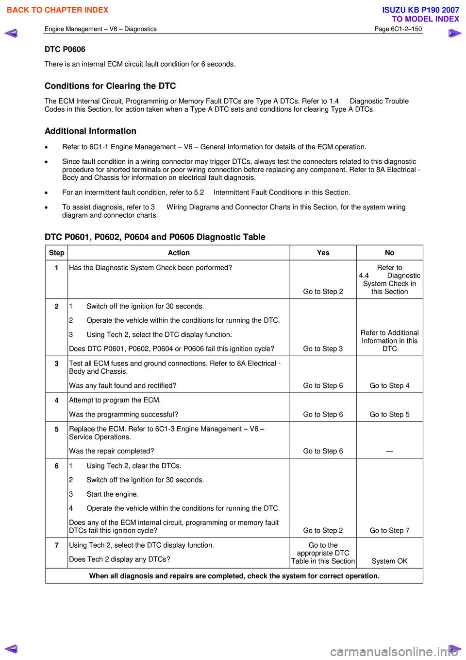
DTC P0601, P0602, P0604 and P0606 Diagnostic Table
Step Action Yes No
1 Has the Diagnostic System Check been performed?
Go to Step 2 Refer to
4.4 Diagnostic System Check in this Section
2 1 Switch off the ignition for 30 seconds.
2 Operate the vehicle within the conditions for running the DTC.
3 Using Tech 2, select the DTC display function.
Does DTC P0601, P0602, P0604 or P0606 fail this ignition cycle? Go to Step 3 Refer to Additional
Information in this DTC
3 Test all ECM fuses and ground connections. Refer to 8A Electrical -
Body and Chassis.
W as any fault found and rectified? Go to Step 6 Go to Step 4
4 Attempt to program the ECM.
W as the programming successful? Go to Step 6 Go to Step 5
5 Replace the ECM. Refer to 6C1-3 Engine Management – V6 –
Service Operations.
W as the repair completed? Go to Step 6 —
6 1 Using Tech 2, clear the DTCs.
2 Switch off the ignition for 30 seconds.
3 Start the engine.
4 Operate the vehicle within the conditions for running the DTC.
Does any of the ECM internal circuit, programming or memory fault
DTCs fail this ignition cycle? Go to Step 2 Go to Step 7
7 Using Tech 2, select the DTC display function.
Does Tech 2 display any DTCs? Go to the
appropriate DTC
Table in this Section System OK
When all diagnosis and repairs are completed, check the system for correct operation.
BACK TO CHAPTER INDEX
TO MODEL INDEX
ISUZU KB P190 2007
Page 3437 of 6020
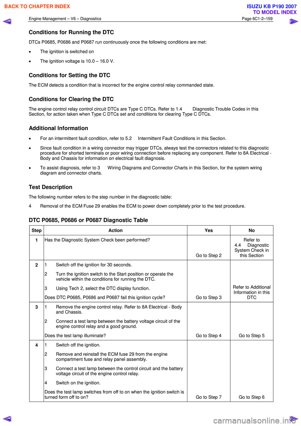
Engine Management – V6 – Diagnostics Page 6C1-2–159
Conditions for Running the DTC
DTCs P0685, P0686 and P0687 run continuously once the following conditions are met:
• The ignition is switched on
• The ignition voltage is 10.0 – 16.0 V.
Conditions for Setting the DTC
The ECM detects a condition that is incorrect for the engine control relay commanded state.
Conditions for Clearing the DTC
The engine control relay control circuit DTCs are Type C DTCs. Refer to 1.4 Diagnostic Trouble Codes in this
Section, for action taken when Type C DTCs set and conditions for clearing Type C DTCs.
Additional Information
• For an intermittent fault condition, refer to 5.2 Intermittent Fault Conditions in this Section.
• Since fault condition in a wiring connector may trigger DTCs, always test the connectors related to this diagnostic
procedure for shorted terminals or poor wiring connection before replacing any component. Refer to 8A Electrical -
Body and Chassis for information on electrical fault diagnosis.
• To assist diagnosis, refer to 3 W iring Diagrams and Connector Charts in this Section, for the system wiring
diagram and connector charts.
Test Description
The following number refers to the step number in the diagnostic table:
4 Removal of the ECM Fuse 29 enables the ECM to power down completely prior to the test procedure.
DTC P0685, P0686 or P0687 Diagnostic Table
Step Action Yes No
1 Has the Diagnostic System Check been performed?
Go to Step 2 Refer to
4.4 Diagnostic
System Check in this Section
2 1 Switch off the ignition for 30 seconds.
2 Turn the ignition switch to the Start position or operate the vehicle within the conditions for running the DTC.
3 Using Tech 2, select the DTC display function.
Does DTC P0685, P0686 and P0687 fail this ignition cycle? Go to Step 3 Refer to Additional
Information in this DTC
3 1 Remove the engine control relay. Refer to 8A Electrical - Body
and Chassis.
2 Connect a test lamp between the battery voltage circuit of the engine control relay and a good ground.
Does the test lamp illuminate? Go to Step 4 Go to Step 5
4 1 Switch off the ignition.
2 Remove and reinstall the ECM fuse 29 from the engine compartment fuse and relay panel assembly.
3 Connect a test lamp between the control circuit and the battery voltage circuit of the engine control relay.
4 Switch on the ignition.
Does the test lamp switches from off to on when the ignition switch is
turned form off to on? Go to Step 7 Go to Step 6
BACK TO CHAPTER INDEX
TO MODEL INDEX
ISUZU KB P190 2007
Page 3460 of 6020
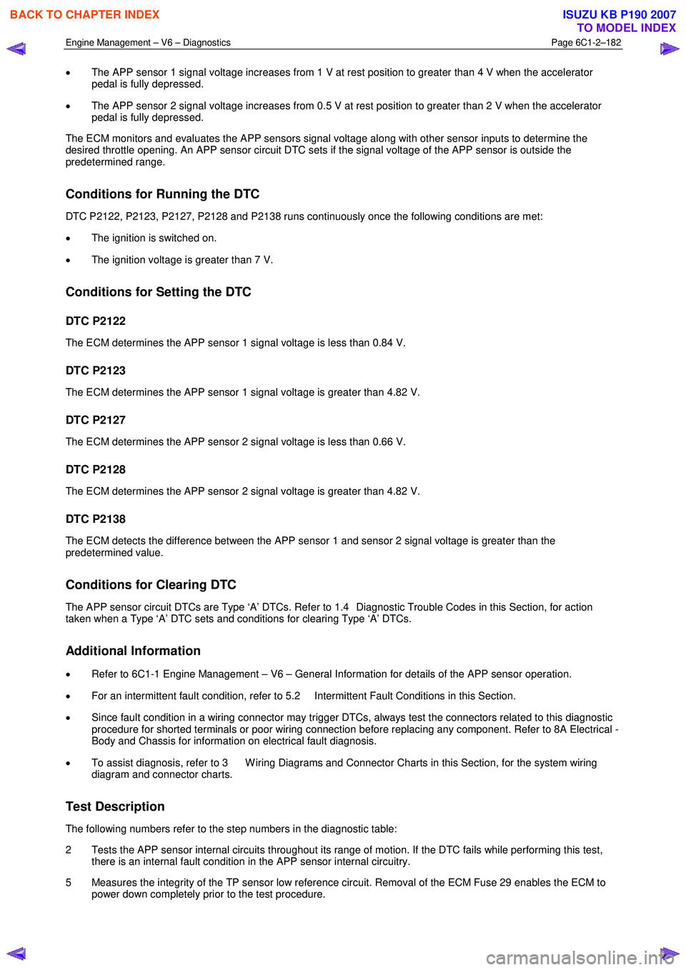
Engine Management – V6 – Diagnostics Page 6C1-2–182
• The APP sensor 1 signal voltage increases from 1 V at rest position to greater than 4 V when the accelerator
pedal is fully depressed.
• The APP sensor 2 signal voltage increases from 0.5 V at rest position to greater than 2 V when the accelerator
pedal is fully depressed.
The ECM monitors and evaluates the APP sensors signal voltage along with other sensor inputs to determine the
desired throttle opening. An APP sensor circuit DTC sets if the signal voltage of the APP sensor is outside the
predetermined range.
Conditions for Running the DTC
DTC P2122, P2123, P2127, P2128 and P2138 runs continuously once the following conditions are met:
• The ignition is switched on.
• The ignition voltage is greater than 7 V.
Conditions for Setting the DTC
DTC P2122
The ECM determines the APP sensor 1 signal voltage is less than 0.84 V.
DTC P2123
The ECM determines the APP sensor 1 signal voltage is greater than 4.82 V.
DTC P2127
The ECM determines the APP sensor 2 signal voltage is less than 0.66 V.
DTC P2128
The ECM determines the APP sensor 2 signal voltage is greater than 4.82 V.
DTC P2138
The ECM detects the difference between the APP sensor 1 and sensor 2 signal voltage is greater than the
predetermined value.
Conditions for Clearing DTC
The APP sensor circuit DTCs are Type ‘A’ DTCs. Refer to 1.4 Diagnostic Trouble Codes in this Section, for action
taken when a Type ‘A’ DTC sets and conditions for clearing Type ‘A’ DTCs.
Additional Information
• Refer to 6C1-1 Engine Management – V6 – General Information for details of the APP sensor operation.
• For an intermittent fault condition, refer to 5.2 Intermittent Fault Conditions in this Section.
• Since fault condition in a wiring connector may trigger DTCs, always test the connectors related to this diagnostic
procedure for shorted terminals or poor wiring connection before replacing any component. Refer to 8A Electrical -
Body and Chassis for information on electrical fault diagnosis.
• To assist diagnosis, refer to 3 W iring Diagrams and Connector Charts in this Section, for the system wiring
diagram and connector charts.
Test Description
The following numbers refer to the step numbers in the diagnostic table:
2 Tests the APP sensor internal circuits throughout its range of motion. If the DTC fails while performing this test, there is an internal fault condition in the APP sensor internal circuitry.
5 Measures the integrity of the TP sensor low reference circuit. Removal of the ECM Fuse 29 enables the ECM to power down completely prior to the test procedure.
BACK TO CHAPTER INDEX
TO MODEL INDEX
ISUZU KB P190 2007
Page 3484 of 6020
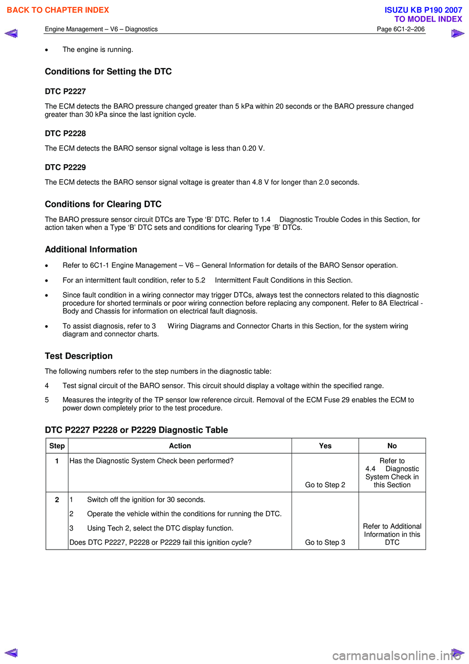
Engine Management – V6 – Diagnostics Page 6C1-2–206
• The engine is running.
Conditions for Setting the DTC
DTC P2227
The ECM detects the BARO pressure changed greater than 5 kPa within 20 seconds or the BARO pressure changed
greater than 30 kPa since the last ignition cycle.
DTC P2228
The ECM detects the BARO sensor signal voltage is less than 0.20 V.
DTC P2229
The ECM detects the BARO sensor signal voltage is greater than 4.8 V for longer than 2.0 seconds.
Conditions for Clearing DTC
The BARO pressure sensor circuit DTCs are Type ‘B’ DTC. Refer to 1.4 Diagnostic Trouble Codes in this Section, for
action taken when a Type ‘B’ DTC sets and conditions for clearing Type ‘B’ DTCs.
Additional Information
• Refer to 6C1-1 Engine Management – V6 – General Information for details of the BARO Sensor operation.
• For an intermittent fault condition, refer to 5.2 Intermittent Fault Conditions in this Section.
• Since fault condition in a wiring connector may trigger DTCs, always test the connectors related to this diagnostic
procedure for shorted terminals or poor wiring connection before replacing any component. Refer to 8A Electrical -
Body and Chassis for information on electrical fault diagnosis.
• To assist diagnosis, refer to 3 W iring Diagrams and Connector Charts in this Section, for the system wiring
diagram and connector charts.
Test Description
The following numbers refer to the step numbers in the diagnostic table:
4 Test signal circuit of the BARO sensor. This circuit should display a voltage within the specified range.
5 Measures the integrity of the TP sensor low reference circuit. Removal of the ECM Fuse 29 enables the ECM to power down completely prior to the test procedure.
DTC P2227 P2228 or P2229 Diagnostic Table
Step Action Yes No
1 Has the Diagnostic System Check been performed?
Go to Step 2 Refer to
4.4 Diagnostic
System Check in this Section
2 1 Switch off the ignition for 30 seconds.
2 Operate the vehicle within the conditions for running the DTC.
3 Using Tech 2, select the DTC display function.
Does DTC P2227, P2228 or P2229 fail this ignition cycle? Go to Step 3 Refer to Additional
Information in this DTC
BACK TO CHAPTER INDEX
TO MODEL INDEX
ISUZU KB P190 2007
Page 3485 of 6020
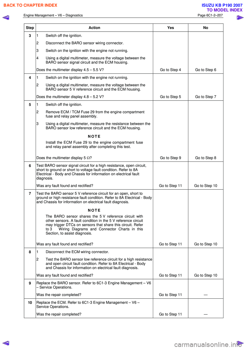
Engine Management – V6 – Diagnostics Page 6C1-2–207
Step Action Yes
No
3 1 Switch off the ignition.
2 Disconnect the BARO sensor wiring connector.
3 Switch on the ignition with the engine not running.
4 Using a digital multimeter, measure the voltage between the BARO sensor signal circuit and the ECM housing.
Does the multimeter display 4.5 – 5.5 V? Go to Step 4 Go to Step 6
4 1 Switch on the ignition with the engine not running.
2 Using a digital multimeter, measure the voltage between the BARO sensor 5 V reference circuit and the ECM housing.
Does the multimeter display 4.8 – 5.2 V? Go to Step 5 Go to Step 7
5 1 Switch off the ignition.
2 Remove ECM / TCM Fuse 29 from the engine compartment fuse and relay panel assembly.
3 Using a digital multimeter, measure the resistance between the BARO sensor low reference circuit and the ECM housing.
NOTE
Install the ECM Fuse 29 to the engine compartment fuse
and relay panel assembly after completing this test.
Does the multimeter display 5 Ω? Go to Step 9 Go to Step 8
6 Test BARO sensor signal circuit for a high resistance, open circuit,
short to ground or short to voltage fault condition. Refer to 8A
Electrical - Body and Chassis for information on electrical fault
diagnosis.
W as any fault found and rectified? Go to Step 11 Go to Step 10
7 Test the BARO sensor 5 V reference circuit for an open, short to
ground or high resistance fault condition. Refer to 8A Electrical - Body
and Chassis for information on electrical fault diagnosis.
NOTE
The BARO sensor shares the 5 V reference circuit with
other sensors. A fault condition in the 5 V reference circuit
may trigger DTCs on sensors that share this circuit. Refer
to 3 W iring Diagrams and Connector Charts in this
Section, to assist diagnosis.
W as any fault found and rectified? Go to Step 11 Go to Step 10
8 1 Disconnect the ECM wiring connector.
2 Test the BARO sensor low reference circuit for a high resistance and open circuit fault condition. Refer to 8A Electrical - Body
and Chassis for information on electrical fault diagnosis.
W as any fault found and rectified? Go to Step 11 Go to Step 10
9 Replace the BARO sensor. Refer to 6C1-3 Engine Management – V6
– Service Operations.
W as the repair completed? Go to Step 11 —
10 Replace the ECM. Refer to 6C1-3 Engine Management – V6 –
Service Operations.
W as the repair completed? Go to Step 11 —
BACK TO CHAPTER INDEX
TO MODEL INDEX
ISUZU KB P190 2007