2007 ISUZU KB P190 Diagram
[x] Cancel search: DiagramPage 5542 of 6020
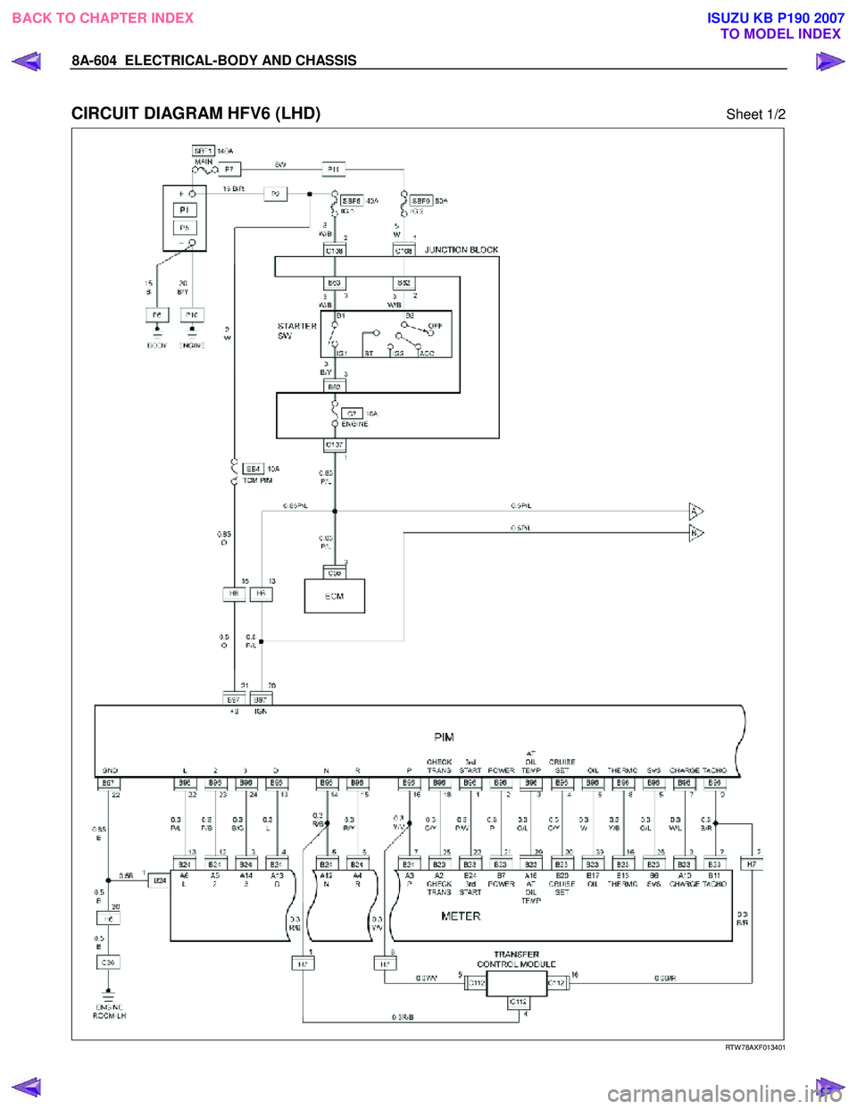
8A-604 ELECTRICAL-BODY AND CHASSIS
CIRCUIT DIAGRAM HFV6 (LHD) Sheet 1/2
RTW 78AXF013401
BACK TO CHAPTER INDEX TO MODEL INDEXISUZU KB P190 2007
Page 5543 of 6020
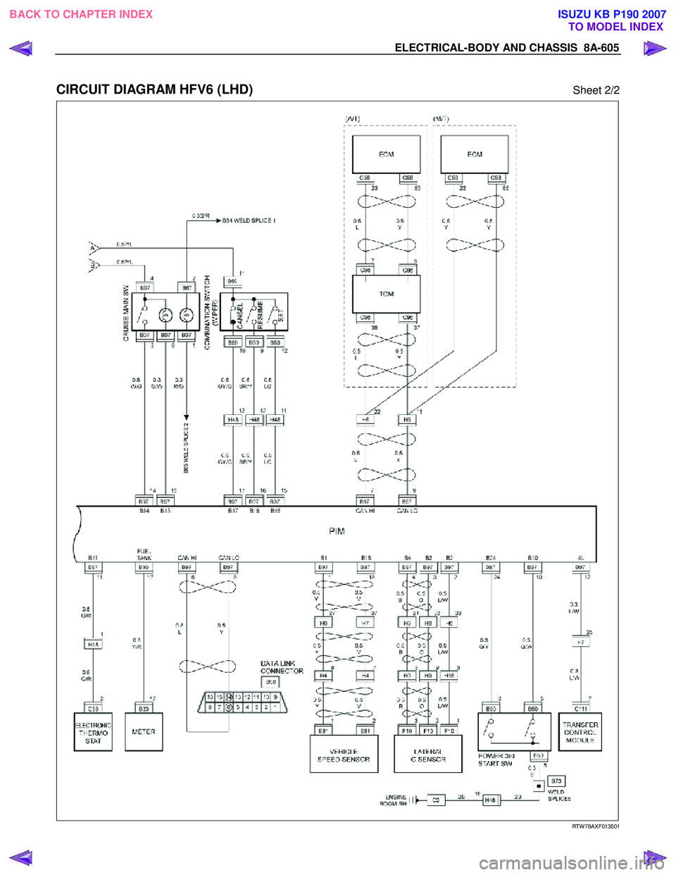
ELECTRICAL-BODY AND CHASSIS 8A-605
CIRCUIT DIAGRAM HFV6 (LHD) Sheet 2/2
RTW 78AXF013501
BACK TO CHAPTER INDEX TO MODEL INDEXISUZU KB P190 2007
Page 5579 of 6020
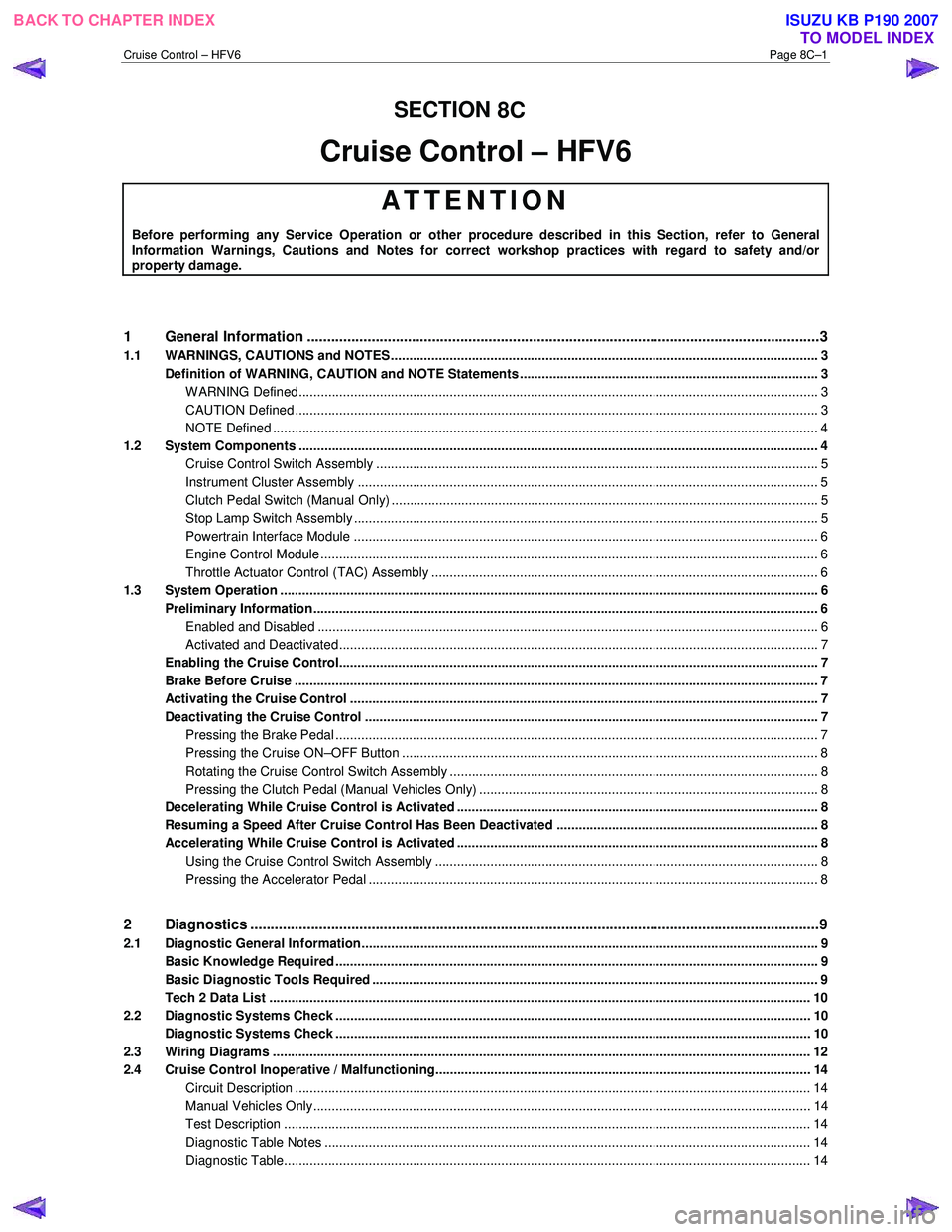
Cruise Control – HFV6 Page 8C–1
8C
Cruise Control – HFV6
ATTENTION
Before performing any Service Operation or other procedure described in this Section, refer to General Information Warnings, Cautions and Notes for correct workshop practices with regard to safety and/or property damage.
1 General Information ...............................................................................................................................3
1.1 WARNINGS, CAUTIONS and NOTES................................................................................................... ................. 3
Definition of WARNING, CAUTION and NOTE Statements ............................................................................. .... 3
WARNING Defined............................................................................................................................................. 3
CAUTION Defined .............................................................................................................................................. 3
NOTE Defined .................................................................................................................................................... 4
1.2 System Components .............................................................................................................. ............................... 4
Cruise Control Switch Assembly ................................................................................................. ....................... 5
Instrument Cluster Assembly ............................................................................................................................. 5
Clutch Pedal Switch (Manual Only) .............................................................................................. ...................... 5
Stop Lamp Switch Assembly .............................................................................................................................. 5
Powertrain Interface Module .............................................................................................................................. 6
Engine Control Module ....................................................................................................................................... 6
Throttle Actuator Control (TAC) Assembly ....................................................................................... .................. 6
1.3 System Operation .................................................................................................................................................. 6
Preliminary Information......................................................................................................................................... 6
Enabled and Disabled ........................................................................................................... ............................. 6
Activated and Deactivated...................................................................................................... ............................ 7
Enabling the Cruise Control.................................................................................................... .............................. 7
Brake Before Cruise .............................................................................................................................................. 7
Activating the Cruise Control .................................................................................................. ............................. 7
Deactivating the Cruise Control ................................................................................................ ........................... 7
Pressing the Brake Pedal ................................................................................................................................... 7
Pressing the Cruise ON–OFF Button .............................................................................................. ................... 8
Rotating the Cruise Control Switch Assembly .................................................................................... ................ 8
Pressing the Clutch Pedal (Manual Vehicles Only) ............................................................................... ............. 8
Decelerating While Cruise Control is Activated ................................................................................. ................. 8
Resuming a Speed After Cruise Control Has Been Deactivated ..................................................................... .. 8
Accelerating While Cruise Control is Activated .................................................................................................. 8
Using the Cruise Control Switch Assembly ........................................................................................................ 8
Pressing the Accelerator Pedal .......................................................................................................................... 8
2 Diagnostics .............................................................................................................................................9
2.1 Diagnostic General Information............................................................................................................................ 9
Basic Knowledge Required ................................................................................................................................... 9
Basic Diagnostic Tools Required ......................................................................................................................... 9
Tech 2 Data List ................................................................................................................................................... 10
2.2 Diagnostic Systems Check ....................................................................................................... .......................... 10
Diagnostic Systems Check ................................................................................................................................. 10
2.3 Wiring Diagrams .................................................................................................................................................. 12
2.4 Cruise Control Inoperative / Malfunctioning.................................................................................... .................. 14
Circuit Description ............................................................................................................................................ 14
Manual Vehicles Only........................................................................................................... ............................ 14
Test Description ............................................................................................................................................... 14
Diagnostic Table Notes ......................................................................................................... ........................... 14
Diagnostic Table............................................................................................................................................... 14
SECTION
BACK TO CHAPTER INDEX
TO MODEL INDEX
ISUZU KB P190 2007
Page 5583 of 6020
Cruise Control – HFV6 Page 8C–5
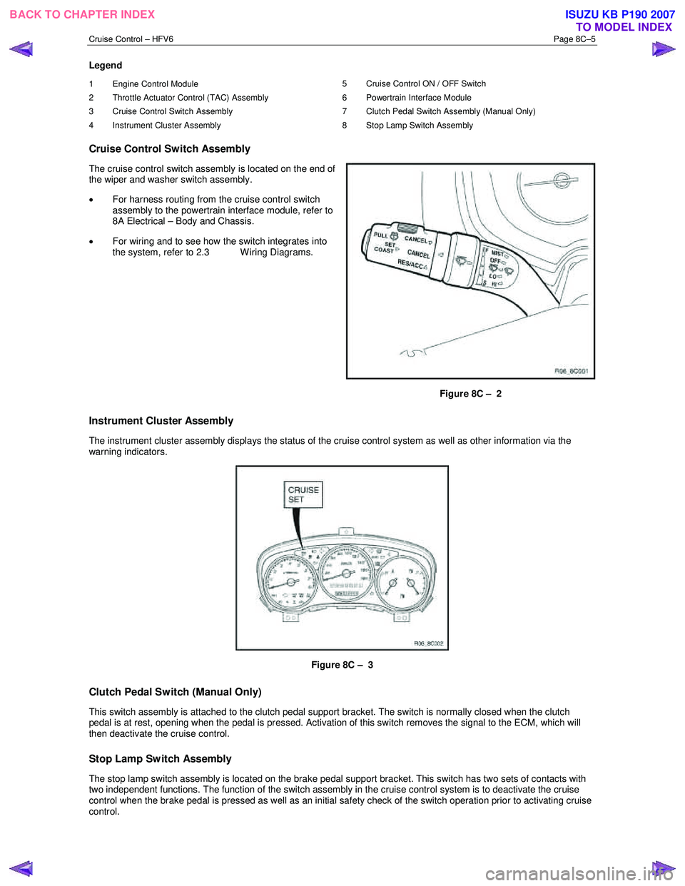
Legend
1 Engine Control Module
2 Throttle Actuator Control (TAC) Assembly
3 Cruise Control Switch Assembly
4 Instrument Cluster Assembly 5 Cruise Control ON / OFF Switch
6 Powertrain Interface Module
7 Clutch Pedal Switch Assembly (Manual Only)
8 Stop Lamp Switch Assembly
Cruise Control Switch Assembly
The cruise control switch assembly is located on the end of
the wiper and washer switch assembly.
• For harness routing from the cruise control switch
assembly to the powertrain interface module, refer to
8A Electrical – Body and Chassis.
• For wiring and to see how the switch integrates into
the system, refer to 2.3 W iring Diagrams.
Figure 8C – 2
Instrument Cluster Assembly
The instrument cluster assembly displays the status of the cruise control system as well as other information via the
warning indicators.
Figure 8C – 3
Clutch Pedal Switch (Manual Only)
This switch assembly is attached to the clutch pedal support bracket. The switch is normally closed when the clutch
pedal is at rest, opening when the pedal is pressed. Activation of this switch removes the signal to the ECM, which will
then deactivate the cruise control.
Stop Lamp Switch Assembly
The stop lamp switch assembly is located on the brake pedal support bracket. This switch has two sets of contacts with
two independent functions. The function of the switch assembly in the cruise control system is to deactivate the cruise
control when the brake pedal is pressed as well as an initial safety check of the switch operation prior to activating cruise
control.
BACK TO CHAPTER INDEX TO MODEL INDEXISUZU KB P190 2007
Page 5585 of 6020
Cruise Control – HFV6 Page 8C–7
Activated and Deactivated
When the cruise control is enabled, the vehicle speed must be above 40 km/h and the cruise control switch assembly
pressed to SET–COAST, the cruise control will be activated and the vehicle will maintain the set speed. When
deactivated by the methods described within this section, the vehicle will no longer maintain the set speed, but the cruise
control will still be engaged.
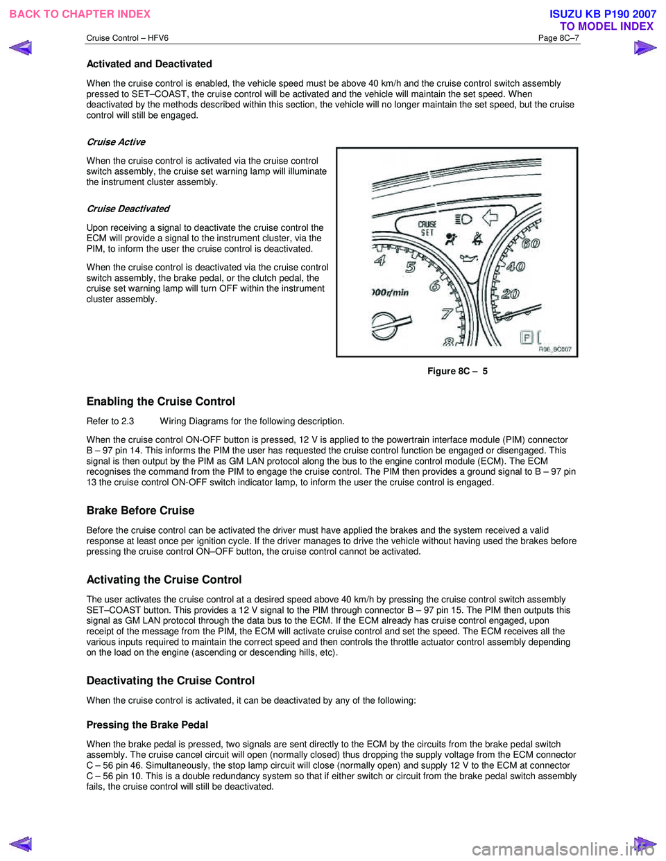
Cruise Active
When the cruise control is activated via the cruise control
switch assembly, the cruise set warning lamp will illuminate
the instrument cluster assembly.
Cruise Deactivated
Upon receiving a signal to deactivate the cruise control the
ECM will provide a signal to the instrument cluster, via the
PIM, to inform the user the cruise control is deactivated.
When the cruise control is deactivated via the cruise control
switch assembly, the brake pedal, or the clutch pedal, the
cruise set warning lamp will turn OFF within the instrument
cluster assembly.
Figure 8C – 5
Enabling the Cruise Control
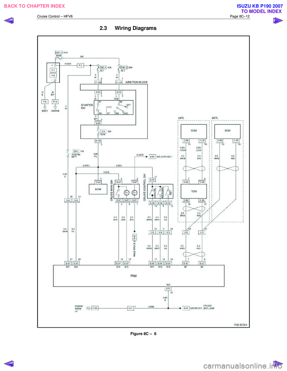
Refer to 2.3 Wiring Diagrams for the following description.
W hen the cruise control ON-OFF button is pressed, 12 V is applied to the powertrain interface module (PIM) connector
B – 97 pin 14. This informs the PIM the user has requested the cruise control function be engaged or disengaged. This
signal is then output by the PIM as GM LAN protocol along the bus to the engine control module (ECM). The ECM
recognises the command from the PIM to engage the cruise control. The PIM then provides a ground signal to B – 97 pin
13 the cruise control ON-OFF switch indicator lamp, to inform the user the cruise control is engaged.
Brake Before Cruise
Before the cruise control can be activated the driver must have applied the brakes and the system received a valid
response at least once per ignition cycle. If the driver manages to drive the vehicle without having used the brakes before
pressing the cruise control ON–OFF button, the cruise control cannot be activated.
Activating the Cruise Control
The user activates the cruise control at a desired speed above 40 km/h by pressing the cruise control switch assembly
SET–COAST button. This provides a 12 V signal to the PIM through connector B – 97 pin 15. The PIM then outputs this
signal as GM LAN protocol through the data bus to the ECM. If the ECM already has cruise control engaged, upon
receipt of the message from the PIM, the ECM will activate cruise control and set the speed. The ECM receives all the
various inputs required to maintain the correct speed and then controls the throttle actuator control assembly depending
on the load on the engine (ascending or descending hills, etc).
Deactivating the Cruise Control
When the cruise control is activated, it can be deactivated by any of the following:
Pressing the Brake Pedal
When the brake pedal is pressed, two signals are sent directly to the ECM by the circuits from the brake pedal switch
assembly. The cruise cancel circuit will open (normally closed) thus dropping the supply voltage from the ECM connector
C – 56 pin 46. Simultaneously, the stop lamp circuit will close (normally open) and supply 12 V to the ECM at connector
C – 56 pin 10. This is a double redundancy system so that if either switch or circuit from the brake pedal switch assembly
fails, the cruise control will still be deactivated.
BACK TO CHAPTER INDEX TO MODEL INDEXISUZU KB P190 2007
Page 5587 of 6020
Cruise Control – HFV6 Page 8C–9
2 Diagnostics
2.1 Diagnostic General Information
Basic Knowledge Required
A lack of basic understanding regarding
electronics, electrical wiring circuits and use
of electrical circuit testing tools when
performing the cruise control diagnostic
procedures could result in incorrect
diagnostic results or damage to components.
A general understanding of basic electronics, electrical wiring circuits and the correct use of the basic electrical circuit
testing tools is required to perform the diagnostic procedures detailed in this Section. Refer to 8A Electrical – Body and
Chassis W iring Diagrams for information on electrical circuits.
In addition, a general understanding of the cruise control and its component operation is essential to prevent
misdiagnosis and component damage.
Basic Diagnostic Tools Required
Use of incorrect electrical circuit diagnostic
tools when performing the cruise control
diagnostic procedures could result in
incorrect diagnostic results or damage to
components.
The following electrical circuit testing tools are required to perform the diagnostic procedures detailed in this Section:
• test lamp,
• digital multimeter with 10 meg ohms impedance, and
• connector test adapter kit Tool No. KM609.
For further information on the use of these tools, refer to 8A Electrical – Body and Chassis W iring Diagrams.
BACK TO CHAPTER INDEX TO MODEL INDEXISUZU KB P190 2007
Page 5588 of 6020
Cruise Control – HFV6 Page 8C–10
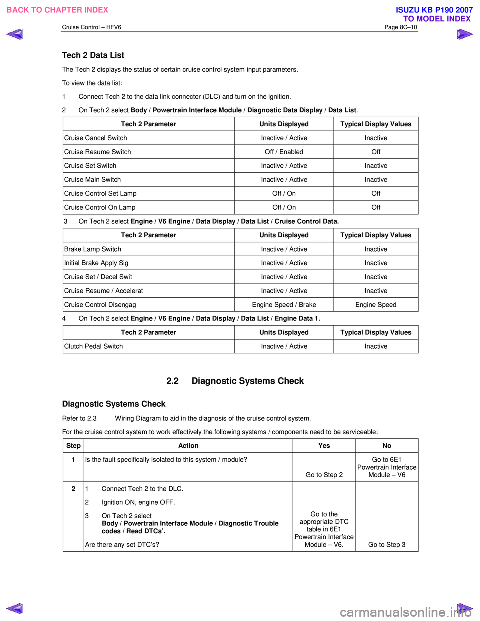
Tech 2 Data List
The Tech 2 displays the status of certain cruise control system input parameters.
To view the data list:
1 Connect Tech 2 to the data link connector (DLC) and turn on the ignition.
2 On Tech 2 select Body / Powertrain Interface Module / Diagnostic Data Display / Data List .
Tech 2 Parameter Units Displayed Typical Display Values
Cruise Cancel Switch Inactive / Active Inactive
Cruise Resume Switch Off / Enabled Off
Cruise Set Switch Inactive / Active Inactive
Cruise Main Switch Inactive / Active Inactive
Cruise Control Set Lamp Off / On Off
Cruise Control On Lamp Off / On Off
3 On Tech 2 select Engine / V6 Engine / Data Display / Data List / Cruise Control Data.
Tech 2 Parameter Units Displayed Typical Display Values
Brake Lamp Switch Inactive / Active Inactive
Initial Brake Apply Sig Inactive / Active Inactive
Cruise Set / Decel Swit Inactive / Active Inactive
Cruise Resume / Accelerat Inactive / Active Inactive
Cruise Control Disengag Engine Speed / Brake Engine Speed
4 On Tech 2 select Engine / V6 Engine / Data Display / Data List / Engine Data 1.
Tech 2 Parameter Units Displayed Typical Display Values
Clutch Pedal Switch Inactive / Active Inactive
2.2 Diagnostic Systems Check
Diagnostic Systems Check
Refer to 2.3 Wiring Diagram to aid in the diagnosis of the cruise control system.
For the cruise control system to work effectively the following systems / components need to be serviceable:
Step Action Yes No
1 Is the fault specifically isolated to this system / module?
Go to Step 2 Go to 6E1
Powertrain Interface Module – V6
2 1 Connect Tech 2 to the DLC.
2 Ignition ON, engine OFF.
3 On Tech 2 select Body / Powertrain Interface Module / Diagnostic Trouble
codes / Read DTCs’.
Are there any set DTC’s? Go to the
appropriate DTC table in 6E1
Powertrain Interface Module – V6. Go to Step 3
BACK TO CHAPTER INDEX TO MODEL INDEXISUZU KB P190 2007
Page 5590 of 6020
Cruise Control – HFV6 Page 8C–12
2.3 Wiring Diagrams
Figure 8C – 6
BACK TO CHAPTER INDEX TO MODEL INDEXISUZU KB P190 2007