2007 ISUZU KB P190 ignition
[x] Cancel search: ignitionPage 1789 of 6020
6E-172 ENGINE CONTROL SYSTEM (4JK1/4JJ1)
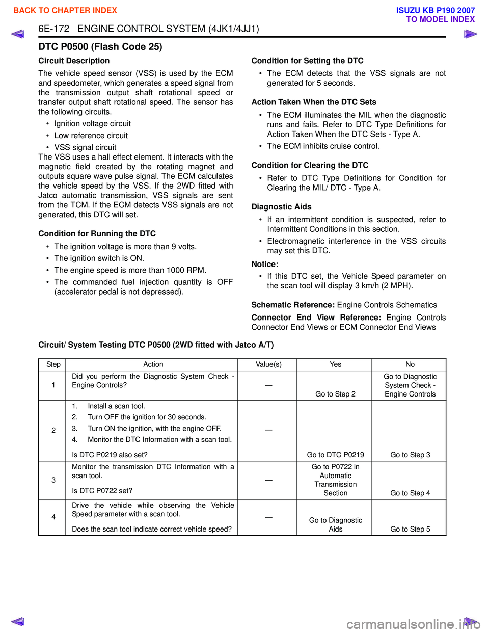
DTC P0500 (Flash Code 25)
Circuit Description
The vehicle speed sensor (VSS) is used by the ECM
and speedometer, which generates a speed signal from
the transmission output shaft rotational speed or
transfer output shaft rotational speed. The sensor has
the following circuits.
• Ignition voltage circuit
• Low reference circuit
• VSS signal circuit
The VSS uses a hall effect element. It interacts with the
magnetic field created by the rotating magnet and
outputs square wave pulse signal. The ECM calculates
the vehicle speed by the VSS. If the 2WD fitted with
Jatco automatic transmission, VSS signals are sent
from the TCM. If the ECM detects VSS signals are not
generated, this DTC will set.
Condition for Running the DTC • The ignition voltage is more than 9 volts.
• The ignition switch is ON.
• The engine speed is more than 1000 RPM.
• The commanded fuel injection quantity is OFF (accelerator pedal is not depressed). Condition for Setting the DTC
• The ECM detects that the VSS signals are not generated for 5 seconds.
Action Taken When the DTC Sets • The ECM illuminates the MIL when the diagnostic runs and fails. Refer to DTC Type Definitions for
Action Taken When the DTC Sets - Type A.
• The ECM inhibits cruise control.
Condition for Clearing the DTC • Refer to DTC Type Definitions for Condition for Clearing the MIL/ DTC - Type A.
Diagnostic Aids • If an intermittent condition is suspected, refer to Intermittent Conditions in this section.
• Electromagnetic interference in the VSS circuits may set this DTC.
Notice: • If this DTC set, the Vehicle Speed parameter on the scan tool will display 3 km/h (2 MPH).
Schematic Reference: Engine Controls Schematics
Connector End View Reference: Engine Controls
Connector End Views or ECM Connector End Views
Circuit/ System Testing DTC P0500 (2WD fitted with Jatco A/T)
Step Action Value(s)Yes No
1 Did you perform the Diagnostic System Check -
Engine Controls? —
Go to Step 2 Go to Diagnostic
System Check -
Engine Controls
2 1. Install a scan tool.
2. Turn OFF the ignition for 30 seconds.
3. Turn ON the ignition, with the engine OFF.
4. Monitor the DTC Information with a scan tool.
Is DTC P0219 also set? —
Go to DTC P0219 Go to Step 3
3 Monitor the transmission DTC Information with a
scan tool.
Is DTC P0722 set? —Go to P0722 in
Automatic
Transmission
Section Go to Step 4
4 Drive the vehicle while observing the Vehicle
Speed parameter with a scan tool.
Does the scan tool indicate correct vehicle speed? —
Go to Diagnostic
Aids Go to Step 5
BACK TO CHAPTER INDEX
TO MODEL INDEX
ISUZU KB P190 2007
Page 1790 of 6020
ENGINE CONTROL SYSTEM (4JK1/4JJ1) 6E-173
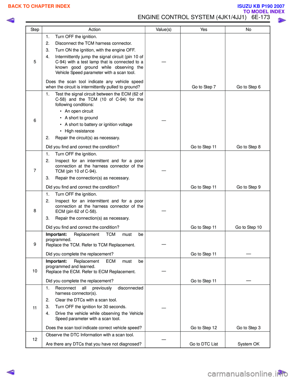
51. Turn OFF the ignition.
2. Disconnect the TCM harness connector.
3. Turn ON the ignition, with the engine OFF.
4. Intermittently jump the signal circuit (pin 10 of C-94) with a test lamp that is connected to a
known good ground while observing the
Vehicle Speed parameter with a scan tool.
Does the scan tool indicate any vehicle speed
when the circuit is intermittently pulled to ground? —
Go to Step 7 Go to Step 6
6 1. Test the signal circuit between the ECM (62 of
C-58) and the TCM (10 of C-94) for the
following conditions:
• An open circuit
• A short to ground
• A short to battery or ignition voltage
• High resistance
2. Repair the circuit(s) as necessary.
Did you find and correct the condition? —
Go to Step 11 Go to Step 8
7 1. Turn OFF the ignition.
2. Inspect for an intermittent and for a poor connection at the harness connector of the
TCM (pin 10 of C-94).
3. Repair the connection(s) as necessary.
Did you find and correct the condition? —
Go to Step 11 Go to Step 9
8 1. Turn OFF the ignition.
2. Inspect for an intermittent and for a poor connection at the harness connector of the
ECM (pin 62 of C-58).
3. Repair the connection(s) as necessary.
Did you find and correct the condition? —
Go to Step 11 Go to Step 10
9 Important:
Replacement TCM must be
programmed.
Replace the TCM. Refer to TCM Replacement.
Did you complete the replacement? —
Go to Step 11
—
10Important:
Replacement ECM must be
programmed and learned.
Replace the ECM. Refer to ECM Replacement.
Did you complete the replacement? —
Go to Step 11
—
111. Reconnect all previously disconnected
harness connector(s).
2. Clear the DTCs with a scan tool.
3. Turn OFF the ignition for 30 seconds.
4. Drive the vehicle while observing the Vehicle Speed parameter with a scan tool.
Does the scan tool indicate correct vehicle speed? —
Go to Step 12 Go to Step 3
12 Observe the DTC Information with a scan tool.
Are there any DTCs that you have not diagnosed? —
Go to DTC List System OK
Step
Action Value(s)Yes No
BACK TO CHAPTER INDEX
TO MODEL INDEX
ISUZU KB P190 2007
Page 1791 of 6020
6E-174 ENGINE CONTROL SYSTEM (4JK1/4JJ1)
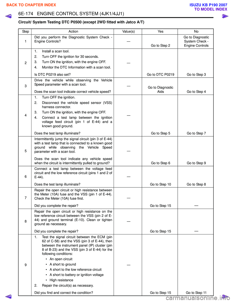
Circuit/ System Testing DTC P0500 (except 2WD fitted with Jatco A/T)
StepAction Value(s)Yes No
1 Did you perform the Diagnostic System Check -
Engine Controls? —
Go to Step 2 Go to Diagnostic
System Check -
Engine Controls
2 1. Install a scan tool.
2. Turn OFF the ignition for 30 seconds.
3. Turn ON the ignition, with the engine OFF.
4. Monitor the DTC Information with a scan tool.
Is DTC P0219 also set? —
Go to DTC P0219 Go to Step 3
3 Drive the vehicle while observing the Vehicle
Speed parameter with a scan tool.
Does the scan tool indicate correct vehicle speed? —
Go to Diagnostic
Aids Go to Step 4
4 1. Turn OFF the ignition.
2. Disconnect the vehicle speed sensor (VSS) harness connector.
3. Turn ON the ignition, with the engine OFF.
4. Connect a test lamp between the ignition voltage feed circuit (pin 1 of E-44) and a
known good ground.
Does the test lamp illuminate? —
Go to Step 5 Go to Step 7
5 Intermittently jump the signal circuit (pin 3 of E-44)
with a test lamp that is connected to a known good
ground while observing the Vehicle Speed
parameter with a scan tool.
Does the scan tool indicate any vehicle speed
when the circuit is intermittently pulled to ground? —
Go to Step 6 Go to Step 9
6 Connect a test lamp between the voltage feed
circuit and the low reference circuit (pins 1 and 2 of
E-44).
Does the test lamp illuminate? —
Go to Step 10 Go to Step 8
7 Repair the open circuit or high resistance between
the Meter (10A) fuse and the VSS (pin 1 of E-44).
Check the Meter (10A) fuse first.
Did you complete the repair? —
Go to Step 15
—
8Repair the open circuit or high resistance on the
low reference circuit between the VSS (pin 2 of E-
44) and ground terminal (E-10). Clean or tighten
ground as necessary.
Did you complete the repair? —
Go to Step 15
—
91. Test the signal circuit between the ECM (pin
62 of C-58) and the VSS (pin 3 of E-44), then
between the instrument panel (IP) cluster (pin
8 of B-23) and the VSS (pin 3 of E-44) for the
following conditions:
• An open circuit
• A short to ground
• A short to the low reference circuit
• A short to battery or ignition voltage
• High resistance
2. Repair the circuit(s) as necessary.
Did you find and correct the condition? —
Go to Step 15 Go to Step 11
BACK TO CHAPTER INDEX
TO MODEL INDEX
ISUZU KB P190 2007
Page 1792 of 6020
ENGINE CONTROL SYSTEM (4JK1/4JJ1) 6E-175
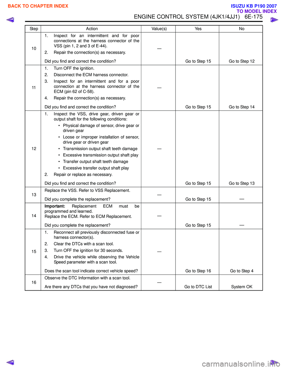
101. Inspect for an intermittent and for poor
connections at the harness connector of the
VSS (pin 1, 2 and 3 of E-44).
2. Repair the connection(s) as necessary.
Did you find and correct the condition? —
Go to Step 15 Go to Step 12
11 1. Turn OFF the ignition.
2. Disconnect the ECM harness connector.
3. Inspect for an intermittent and for a poor connection at the harness connector of the
ECM (pin 62 of C-58).
4. Repair the connection(s) as necessary.
Did you find and correct the condition? —
Go to Step 15 Go to Step 14
12 1. Inspect the VSS, drive gear, driven gear or
output shaft for the following conditions:
• Physical damage of sensor, drive gear or driven gear
• Loose or improper installation of sensor, drive gear or driven gear
• Transmission output shaft teeth damage
• Excessive transmission output shaft play
• Transfer output shaft teeth damage
• Excessive transfer output shaft play
2. Repair or replace as necessary.
Did you find and correct the condition? —
Go to Step 15 Go to Step 13
13 Replace the VSS. Refer to VSS Replacement.
Did you complete the replacement? —
Go to Step 15
—
14Important:
Replacement ECM must be
programmed and learned.
Replace the ECM. Refer to ECM Replacement.
Did you complete the replacement? —
Go to Step 15
—
151. Reconnect all previously disconnected fuse or
harness connector(s).
2. Clear the DTCs with a scan tool.
3. Turn OFF the ignition for 30 seconds.
4. Drive the vehicle while observing the Vehicle Speed parameter with a scan tool.
Does the scan tool indicate correct vehicle speed? —
Go to Step 16 Go to Step 4
16 Observe the DTC Information with a scan tool.
Are there any DTCs that you have not diagnosed? —
Go to DTC List System OK
Step
Action Value(s)Yes No
BACK TO CHAPTER INDEX
TO MODEL INDEX
ISUZU KB P190 2007
Page 1793 of 6020
6E-176 ENGINE CONTROL SYSTEM (4JK1/4JJ1)
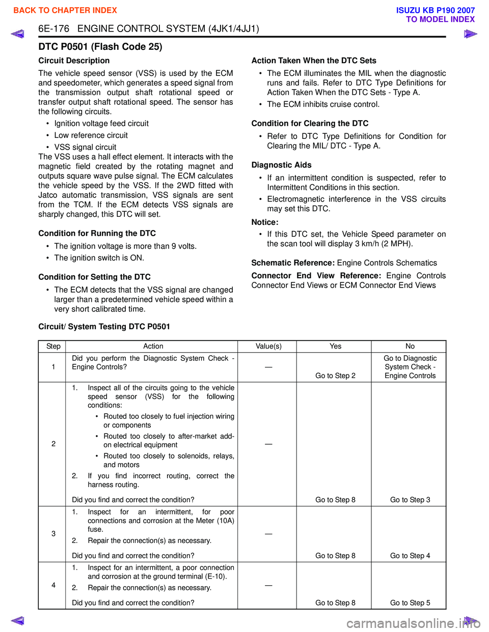
DTC P0501 (Flash Code 25)
Circuit Description
The vehicle speed sensor (VSS) is used by the ECM
and speedometer, which generates a speed signal from
the transmission output shaft rotational speed or
transfer output shaft rotational speed. The sensor has
the following circuits.
• Ignition voltage feed circuit
• Low reference circuit
• VSS signal circuit
The VSS uses a hall effect element. It interacts with the
magnetic field created by the rotating magnet and
outputs square wave pulse signal. The ECM calculates
the vehicle speed by the VSS. If the 2WD fitted with
Jatco automatic transmission, VSS signals are sent
from the TCM. If the ECM detects VSS signals are
sharply changed, this DTC will set.
Condition for Running the DTC • The ignition voltage is more than 9 volts.
• The ignition switch is ON.
Condition for Setting the DTC • The ECM detects that the VSS signal are changed larger than a predetermined vehicle speed within a
very short calibrated time. Action Taken When the DTC Sets
• The ECM illuminates the MIL when the diagnostic runs and fails. Refer to DTC Type Definitions for
Action Taken When the DTC Sets - Type A.
• The ECM inhibits cruise control.
Condition for Clearing the DTC • Refer to DTC Type Definitions for Condition for Clearing the MIL/ DTC - Type A.
Diagnostic Aids • If an intermittent condition is suspected, refer to Intermittent Conditions in this section.
• Electromagnetic interference in the VSS circuits may set this DTC.
Notice: • If this DTC set, the Vehicle Speed parameter on the scan tool will display 3 km/h (2 MPH).
Schematic Reference: Engine Controls Schematics
Connector End View Reference: Engine Controls
Connector End Views or ECM Connector End Views
Circuit/ System Testing DTC P0501
Step Action Value(s)Yes No
1 Did you perform the Diagnostic System Check -
Engine Controls? —
Go to Step 2 Go to Diagnostic
System Check -
Engine Controls
2 1. Inspect all of the circuits going to the vehicle
speed sensor (VSS) for the following
conditions:
• Routed too closely to fuel injection wiring or components
• Routed too closely to after-market add- on electrical equipment
• Routed too closely to solenoids, relays, and motors
2. If you find incorrect routing, correct the harness routing.
Did you find and correct the condition? —
Go to Step 8 Go to Step 3
3 1. Inspect for an intermittent, for poor
connections and corrosion at the Meter (10A)
fuse.
2. Repair the connection(s) as necessary.
Did you find and correct the condition? —
Go to Step 8 Go to Step 4
4 1. Inspect for an intermittent, a poor connection
and corrosion at the ground terminal (E-10).
2. Repair the connection(s) as necessary.
Did you find and correct the condition? —
Go to Step 8 Go to Step 5
BACK TO CHAPTER INDEX
TO MODEL INDEX
ISUZU KB P190 2007
Page 1794 of 6020
ENGINE CONTROL SYSTEM (4JK1/4JJ1) 6E-177
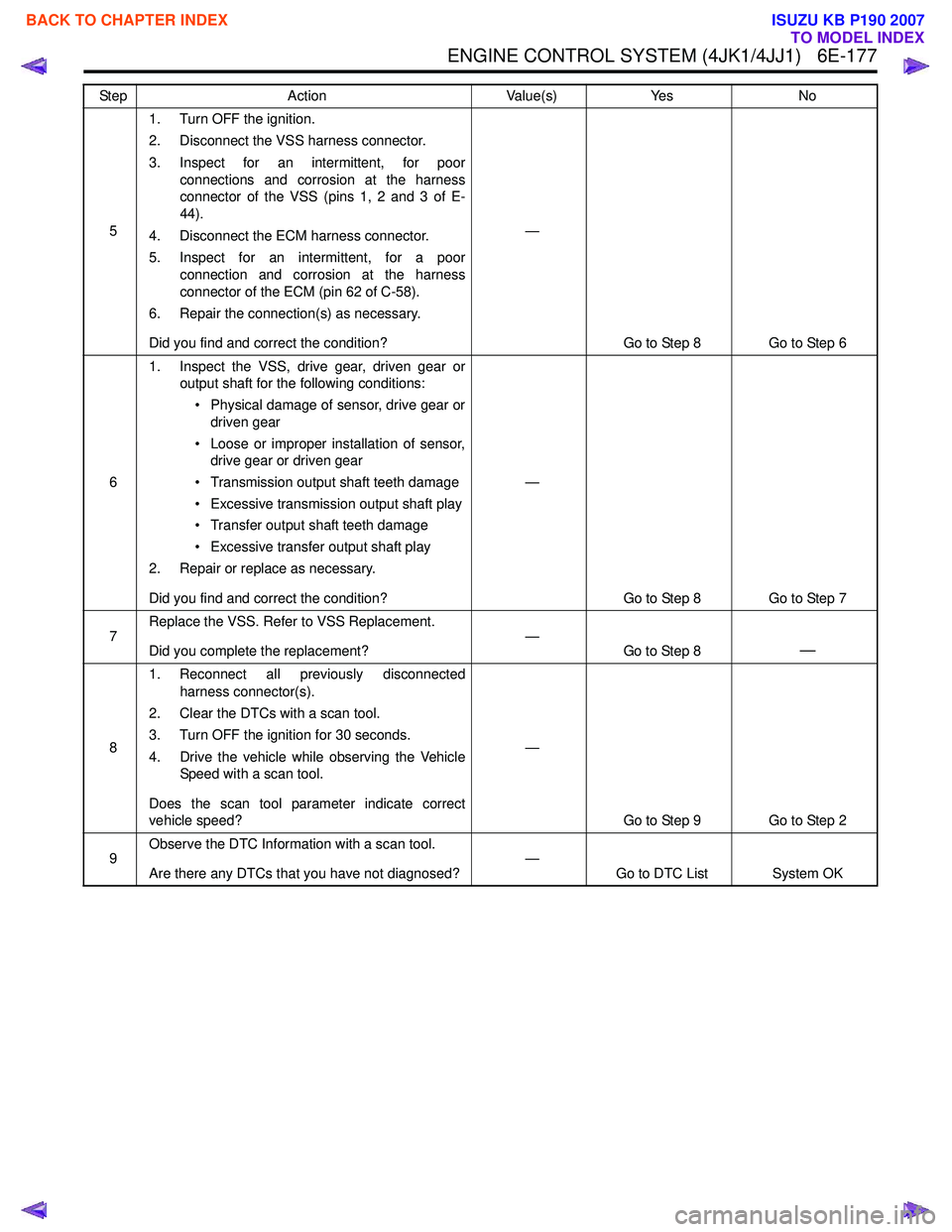
51. Turn OFF the ignition.
2. Disconnect the VSS harness connector.
3. Inspect for an intermittent, for poor connections and corrosion at the harness
connector of the VSS (pins 1, 2 and 3 of E-
44).
4. Disconnect the ECM harness connector.
5. Inspect for an intermittent, for a poor connection and corrosion at the harness
connector of the ECM (pin 62 of C-58).
6. Repair the connection(s) as necessary.
Did you find and correct the condition? —
Go to Step 8 Go to Step 6
6 1. Inspect the VSS, drive gear, driven gear or
output shaft for the following conditions:
• Physical damage of sensor, drive gear or driven gear
• Loose or improper installation of sensor, drive gear or driven gear
• Transmission output shaft teeth damage
• Excessive transmission output shaft play
• Transfer output shaft teeth damage
• Excessive transfer output shaft play
2. Repair or replace as necessary.
Did you find and correct the condition? —
Go to Step 8 Go to Step 7
7 Replace the VSS. Refer to VSS Replacement.
Did you complete the replacement? —
Go to Step 8
—
81. Reconnect all previously disconnected
harness connector(s).
2. Clear the DTCs with a scan tool.
3. Turn OFF the ignition for 30 seconds.
4. Drive the vehicle while observing the Vehicle Speed with a scan tool.
Does the scan tool parameter indicate correct
vehicle speed? —
Go to Step 9 Go to Step 2
9 Observe the DTC Information with a scan tool.
Are there any DTCs that you have not diagnosed? —
Go to DTC List System OK
Step
Action Value(s)Yes No
BACK TO CHAPTER INDEX
TO MODEL INDEX
ISUZU KB P190 2007
Page 1795 of 6020
6E-178 ENGINE CONTROL SYSTEM (4JK1/4JJ1)
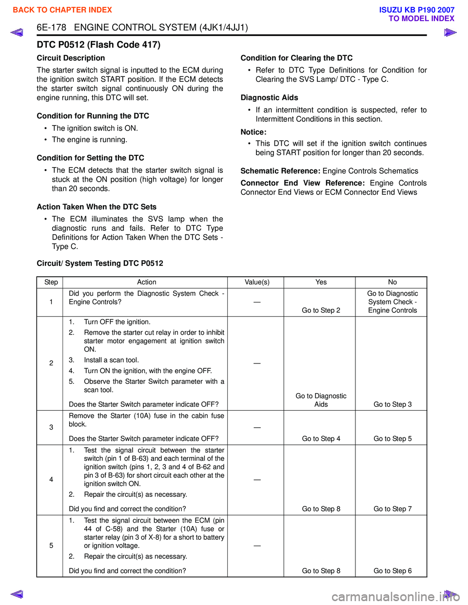
DTC P0512 (Flash Code 417)
Circuit Description
The starter switch signal is inputted to the ECM during
the ignition switch START position. If the ECM detects
the starter switch signal continuously ON during the
engine running, this DTC will set.
Condition for Running the DTC • The ignition switch is ON.
• The engine is running.
Condition for Setting the DTC • The ECM detects that the starter switch signal is stuck at the ON position (high voltage) for longer
than 20 seconds.
Action Taken When the DTC Sets • The ECM illuminates the SVS lamp when the diagnostic runs and fails. Refer to DTC Type
Definitions for Action Taken When the DTC Sets -
Type C. Condition for Clearing the DTC
• Refer to DTC Type Definitions for Condition for Clearing the SVS Lamp/ DTC - Type C.
Diagnostic Aids • If an intermittent condition is suspected, refer to Intermittent Conditions in this section.
Notice: • This DTC will set if the ignition switch continues being START position for longer than 20 seconds.
Schematic Reference: Engine Controls Schematics
Connector End View Reference: Engine Controls
Connector End Views or ECM Connector End Views
Circuit/ System Testing DTC P0512
Step Action Value(s)Yes No
1 Did you perform the Diagnostic System Check -
Engine Controls? —
Go to Step 2 Go to Diagnostic
System Check -
Engine Controls
2 1. Turn OFF the ignition.
2. Remove the starter cut relay in order to inhibit starter motor engagement at ignition switch
ON.
3. Install a scan tool.
4. Turn ON the ignition, with the engine OFF.
5. Observe the Starter Switch parameter with a scan tool.
Does the Starter Switch parameter indicate OFF? —
Go to Diagnostic Aids Go to Step 3
3 Remove the Starter (10A) fuse in the cabin fuse
block.
Does the Starter Switch parameter indicate OFF? —
Go to Step 4 Go to Step 5
4 1. Test the signal circuit between the starter
switch (pin 1 of B-63) and each terminal of the
ignition switch (pins 1, 2, 3 and 4 of B-62 and
pin 3 of B-63) for short circuit each other at the
ignition switch ON.
2. Repair the circuit(s) as necessary.
Did you find and correct the condition? —
Go to Step 8 Go to Step 7
5 1. Test the signal circuit between the ECM (pin
44 of C-58) and the Starter (10A) fuse or
starter relay (pin 3 of X-8) for a short to battery
or ignition voltage.
2. Repair the circuit(s) as necessary.
Did you find and correct the condition? —
Go to Step 8 Go to Step 6
BACK TO CHAPTER INDEX
TO MODEL INDEX
ISUZU KB P190 2007
Page 1796 of 6020
ENGINE CONTROL SYSTEM (4JK1/4JJ1) 6E-179
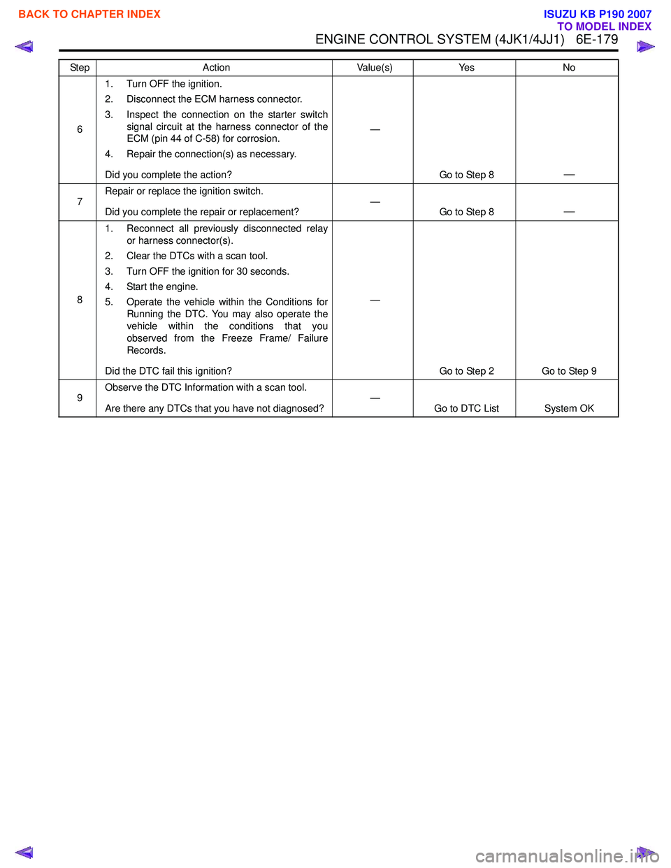
61. Turn OFF the ignition.
2. Disconnect the ECM harness connector.
3. Inspect the connection on the starter switch signal circuit at the harness connector of the
ECM (pin 44 of C-58) for corrosion.
4. Repair the connection(s) as necessary.
Did you complete the action? —
Go to Step 8
—
7Repair or replace the ignition switch.
Did you complete the repair or replacement? —
Go to Step 8—
81. Reconnect all previously disconnected relay
or harness connector(s).
2. Clear the DTCs with a scan tool.
3. Turn OFF the ignition for 30 seconds.
4. Start the engine.
5. Operate the vehicle within the Conditions for Running the DTC. You may also operate the
vehicle within the conditions that you
observed from the Freeze Frame/ Failure
Records.
Did the DTC fail this ignition? —
Go to Step 2 Go to Step 9
9 Observe the DTC Information with a scan tool.
Are there any DTCs that you have not diagnosed? —
Go to DTC List System OK
Step
Action Value(s)Yes No
BACK TO CHAPTER INDEX
TO MODEL INDEX
ISUZU KB P190 2007