2007 ISUZU KB P190 fuel pressure
[x] Cancel search: fuel pressurePage 1081 of 6020
Engine Control System (4JH1) 6E-47
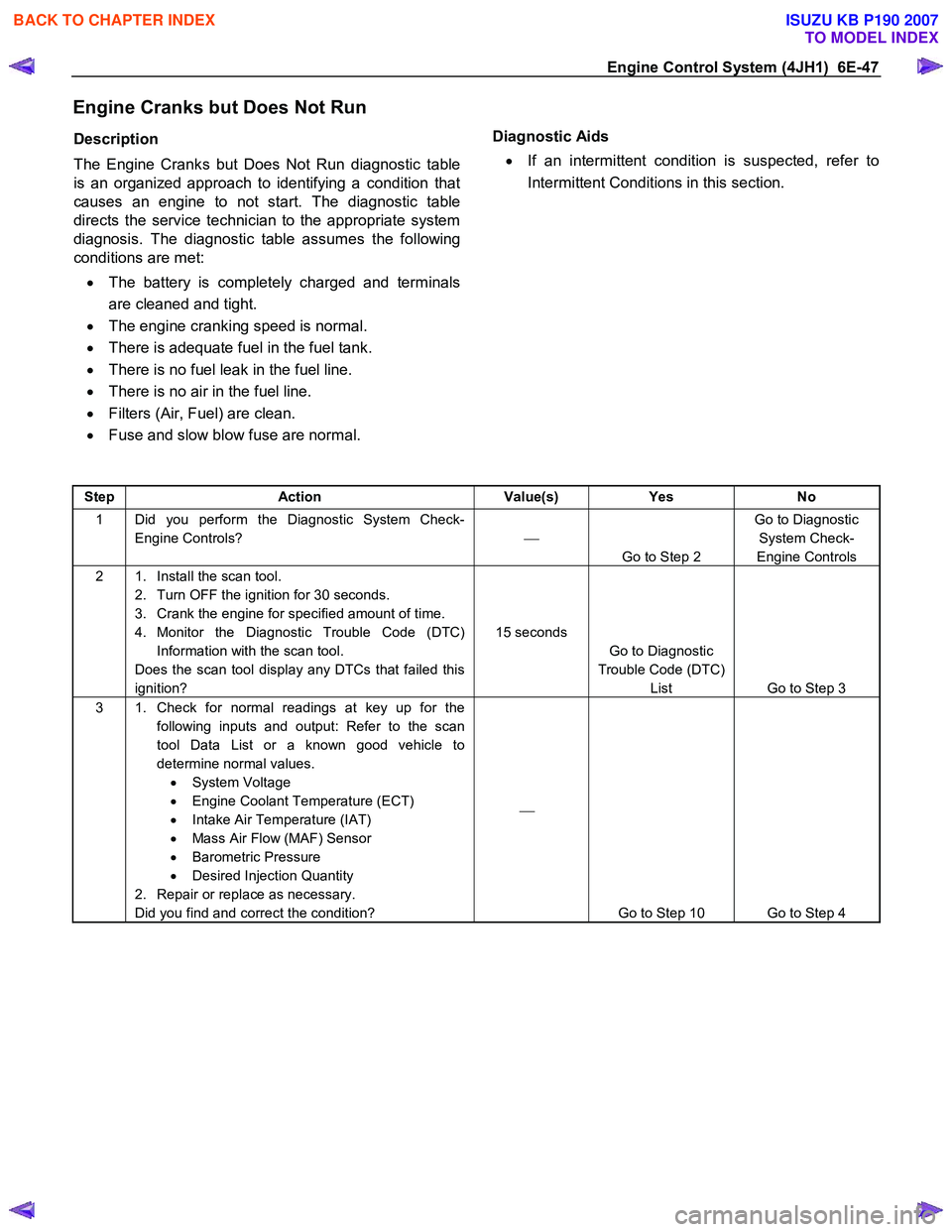
Engine Cranks but Does Not Run
Description
The Engine Cranks but Does Not Run diagnostic table
is an organized approach to identifying a condition that
causes an engine to not start. The diagnostic table
directs the service technician to the appropriate system
diagnosis. The diagnostic table assumes the following
conditions are met:
• The battery is completely charged and terminals
are cleaned and tight.
• The engine cranking speed is normal.
• There is adequate fuel in the fuel tank.
• There is no fuel leak in the fuel line.
• There is no air in the fuel line.
• Filters (Air, Fuel) are clean.
• Fuse and slow blow fuse are normal.
Diagnostic Aids
• If an intermittent condition is suspected, refer to
Intermittent Conditions in this section.
Step Action Value(s) Yes No
1 Did you perform the Diagnostic System Check-
Engine Controls?
Go to Step 2 Go to Diagnostic
System Check-
Engine Controls
2 1. Install the scan tool. 2. Turn OFF the ignition for 30 seconds.
3. Crank the engine for specified amount of time.
4. Monitor the Diagnostic Trouble Code (DTC) Information with the scan tool.
Does the scan tool display any DTCs that failed this
ignition? 15 seconds
Go to Diagnostic
Trouble Code (DTC) List Go to Step 3
3 1. Check for normal readings at key up for the
following inputs and output: Refer to the scan
tool Data List or a known good vehicle to
determine normal values. • System Voltage
• Engine Coolant Temperature (ECT)
• Intake Air Temperature (IAT)
• Mass Air Flow (MAF) Sensor
• Barometric Pressure
• Desired Injection Quantity
2. Repair or replace as necessary.
Did you find and correct the condition?
Go to Step 10 Go to Step 4
BACK TO CHAPTER INDEX
TO MODEL INDEX
ISUZU KB P190 2007
Page 1082 of 6020
6E-48 Engine Control System (4JH1)
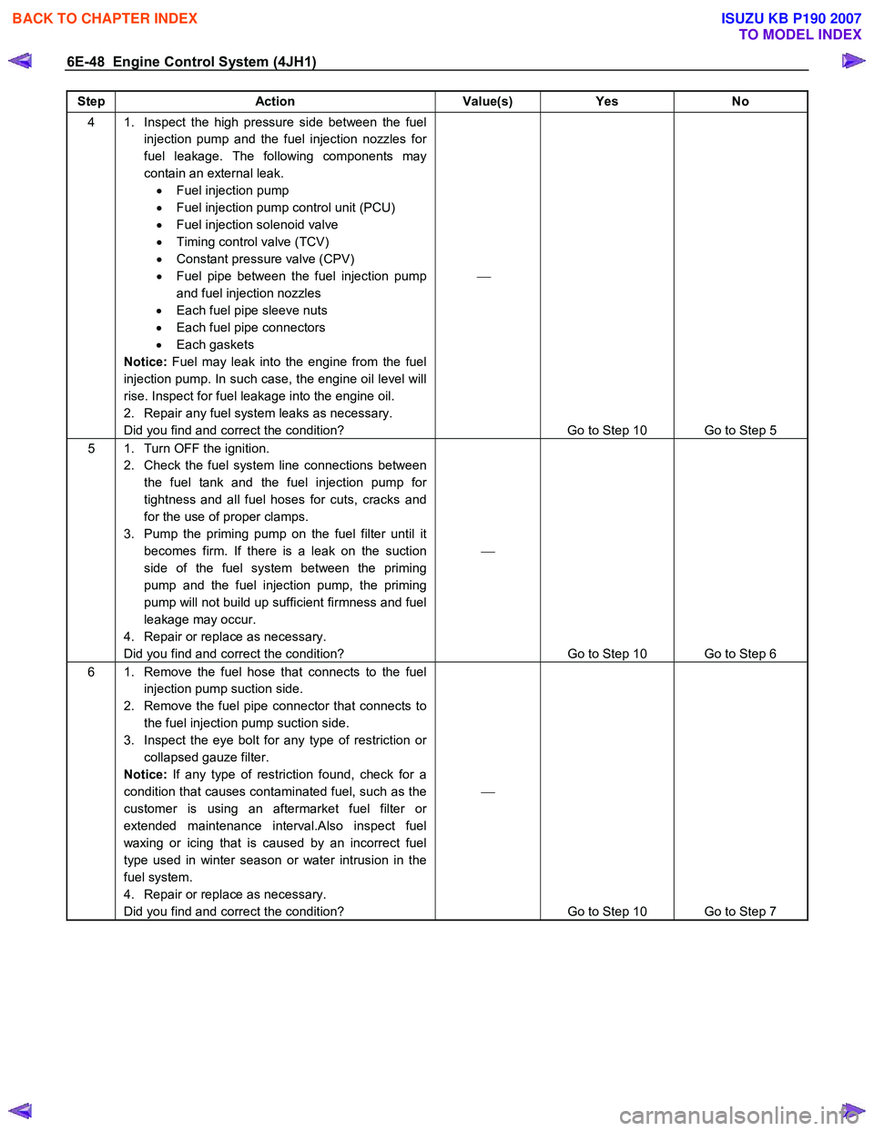
Step Action Value(s) Yes No
4 1. Inspect the high pressure side between the fuel
injection pump and the fuel injection nozzles for
fuel leakage. The following components may
contain an external leak. • Fuel injection pump
• Fuel injection pump control unit (PCU)
• Fuel injection solenoid valve
• Timing control valve (TCV)
• Constant pressure valve (CPV)
• Fuel pipe between the fuel injection pump
and fuel injection nozzles
• Each fuel pipe sleeve nuts
• Each fuel pipe connectors
• Each gaskets
Notice: Fuel may leak into the engine from the fuel
injection pump. In such case, the engine oil level will
rise. Inspect for fuel leakage into the engine oil.
2. Repair any fuel system leaks as necessary.
Did you find and correct the condition?
Go to Step 10 Go to Step 5
5 1. Turn OFF the ignition. 2. Check the fuel system line connections between the fuel tank and the fuel injection pump for
tightness and all fuel hoses for cuts, cracks and
for the use of proper clamps.
3. Pump the priming pump on the fuel filter until it becomes firm. If there is a leak on the suction
side of the fuel system between the priming
pump and the fuel injection pump, the priming
pump will not build up sufficient firmness and fuel
leakage may occur.
4. Repair or replace as necessary.
Did you find and correct the condition?
Go to Step 10 Go to Step 6
6 1. Remove the fuel hose that connects to the fuel injection pump suction side.
2. Remove the fuel pipe connector that connects to the fuel injection pump suction side.
3. Inspect the eye bolt for any type of restriction or collapsed gauze filter.
Notice: If any type of restriction found, check for a
condition that causes contaminated fuel, such as the
customer is using an aftermarket fuel filter or
extended maintenance interval.Also inspect fuel
waxing or icing that is caused by an incorrect fuel
type used in winter season or water intrusion in the
fuel system.
4. Repair or replace as necessary.
Did you find and correct the condition?
Go to Step 10 Go to Step 7
BACK TO CHAPTER INDEX
TO MODEL INDEX
ISUZU KB P190 2007
Page 1109 of 6020
Engine Control System (4JH1) 6E-75
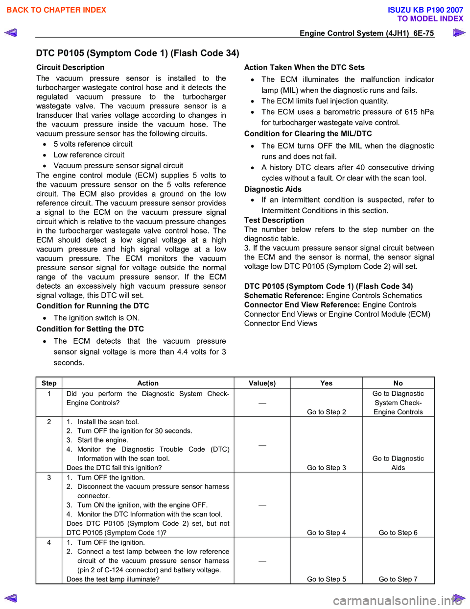
DTC P0105 (Symptom Code 1) (Flash Code 34)
Circuit Description
The vacuum pressure sensor is installed to the
turbocharger wastegate control hose and it detects the
regulated vacuum pressure to the turbocharge
r
wastegate valve. The vacuum pressure sensor is a
transducer that varies voltage according to changes in
the vacuum pressure inside the vacuum hose. The
vacuum pressure sensor has the following circuits.
• 5 volts reference circuit
• Low reference circuit
• Vacuum pressure sensor signal circuit
The engine control module (ECM) supplies 5 volts to
the vacuum pressure sensor on the 5 volts reference
circuit. The ECM also provides a ground on the lo
w
reference circuit. The vacuum pressure sensor provides
a signal to the ECM on the vacuum pressure signal
circuit which is relative to the vacuum pressure changes
in the turbocharger wastegate valve control hose. The
ECM should detect a low signal voltage at a high
vacuum pressure and high signal voltage at a lo
w
vacuum pressure. The ECM monitors the vacuum
pressure sensor signal for voltage outside the normal
range of the vacuum pressure sensor. If the ECM
detects an excessively high vacuum pressure senso
r
signal voltage, this DTC will set.
Condition for Running the DTC
• The ignition switch is ON.
Condition for Setting the DTC
• The ECM detects that the vacuum pressure
sensor signal voltage is more than 4.4 volts for 3
seconds.
Action Taken When the DTC Sets
• The ECM illuminates the malfunction indicato
r
lamp (MIL) when the diagnostic runs and fails.
• The ECM limits fuel injection quantity.
• The ECM uses a barometric pressure of 615 hPa
for turbocharger wastegate valve control.
Condition for Clearing the MIL/DTC
• The ECM turns OFF the MIL when the diagnostic
runs and does not fail.
• A history DTC clears after 40 consecutive driving
cycles without a fault. Or clear with the scan tool.
Diagnostic Aids
• If an intermittent condition is suspected, refer to
Intermittent Conditions in this section.
Test Description
The number below refers to the step number on the
diagnostic table.
3. If the vacuum pressure sensor signal circuit between
the ECM and the sensor is normal, the sensor signal
voltage low DTC P0105 (Symptom Code 2) will set.
DTC P0105 (Symptom Code 1) (Flash Code 34)
Schematic Reference: Engine Controls Schematics
Connector End View Reference: Engine Controls
Connector End Views or Engine Control Module (ECM)
Connector End Views
Step Action Value(s) Yes No
1 Did you perform the Diagnostic System Check-
Engine Controls?
Go to Step 2 Go to Diagnostic
System Check-
Engine Controls
2 1. Install the scan tool. 2. Turn OFF the ignition for 30 seconds.
3. Start the engine.
4. Monitor the Diagnostic Trouble Code (DTC) Information with the scan tool.
Does the DTC fail this ignition?
Go to Step 3 Go to Diagnostic
Aids
3 1. Turn OFF the ignition. 2. Disconnect the vacuum pressure sensor harness connector.
3. Turn ON the ignition, with the engine OFF.
4. Monitor the DTC Information with the scan tool.
Does DTC P0105 (Symptom Code 2) set, but not
DTC P0105 (Symptom Code 1)?
Go to Step 4 Go to Step 6
4 1. Turn OFF the ignition. 2. Connect a test lamp between the low reference circuit of the vacuum pressure sensor harness
(pin 2 of C-124 connector) and battery voltage.
Does the test lamp illuminate?
Go to Step 5 Go to Step 7
BACK TO CHAPTER INDEX
TO MODEL INDEX
ISUZU KB P190 2007
Page 1112 of 6020
6E-78 Engine Control System (4JH1)
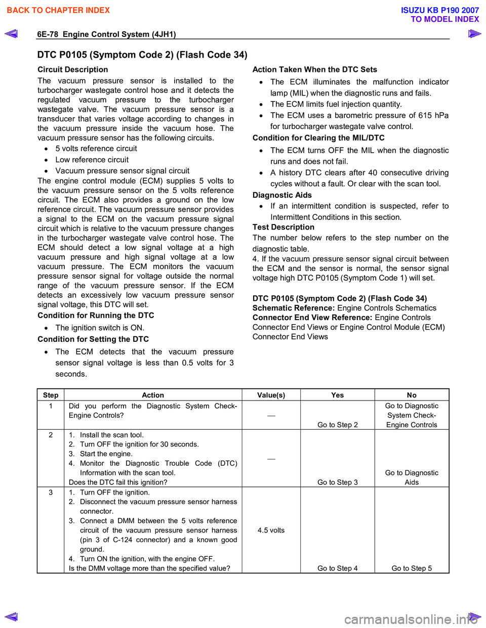
DTC P0105 (Symptom Code 2) (Flash Code 34)
Circuit Description
The vacuum pressure sensor is installed to the
turbocharger wastegate control hose and it detects the
regulated vacuum pressure to the turbocharge
r
wastegate valve. The vacuum pressure sensor is a
transducer that varies voltage according to changes in
the vacuum pressure inside the vacuum hose. The
vacuum pressure sensor has the following circuits.
• 5 volts reference circuit
• Low reference circuit
• Vacuum pressure sensor signal circuit
The engine control module (ECM) supplies 5 volts to
the vacuum pressure sensor on the 5 volts reference
circuit. The ECM also provides a ground on the lo
w
reference circuit. The vacuum pressure sensor provides
a signal to the ECM on the vacuum pressure signal
circuit which is relative to the vacuum pressure changes
in the turbocharger wastegate valve control hose. The
ECM should detect a low signal voltage at a high
vacuum pressure and high signal voltage at a lo
w
vacuum pressure. The ECM monitors the vacuum
pressure sensor signal for voltage outside the normal
range of the vacuum pressure sensor. If the ECM
detects an excessively low vacuum pressure senso
r
signal voltage, this DTC will set.
Condition for Running the DTC
• The ignition switch is ON.
Condition for Setting the DTC
• The ECM detects that the vacuum pressure
sensor signal voltage is less than 0.5 volts for 3
seconds.
Action Taken When the DTC Sets
• The ECM illuminates the malfunction indicato
r
lamp (MIL) when the diagnostic runs and fails.
• The ECM limits fuel injection quantity.
• The ECM uses a barometric pressure of 615 hPa
for turbocharger wastegate valve control.
Condition for Clearing the MIL/DTC
• The ECM turns OFF the MIL when the diagnostic
runs and does not fail.
• A history DTC clears after 40 consecutive driving
cycles without a fault. Or clear with the scan tool.
Diagnostic Aids
• If an intermittent condition is suspected, refer to
Intermittent Conditions in this section.
Test Description
The number below refers to the step number on the
diagnostic table.
4. If the vacuum pressure sensor signal circuit between
the ECM and the sensor is normal, the sensor signal
voltage high DTC P0105 (Symptom Code 1) will set.
DTC P0105 (Symptom Code 2) (Flash Code 34)
Schematic Reference: Engine Controls Schematics
Connector End View Reference: Engine Controls
Connector End Views or Engine Control Module (ECM)
Connector End Views
Step Action Value(s) Yes No
1 Did you perform the Diagnostic System Check-
Engine Controls?
Go to Step 2 Go to Diagnostic
System Check-
Engine Controls
2 1. Install the scan tool. 2. Turn OFF the ignition for 30 seconds.
3. Start the engine.
4. Monitor the Diagnostic Trouble Code (DTC) Information with the scan tool.
Does the DTC fail this ignition?
Go to Step 3 Go to Diagnostic
Aids
3 1. Turn OFF the ignition. 2. Disconnect the vacuum pressure sensor harness connector.
3. Connect a DMM between the 5 volts reference circuit of the vacuum pressure sensor harness
(pin 3 of C-124 connector) and a known good
ground.
4. Turn ON the ignition, with the engine OFF.
Is the DMM voltage more than the specified value? 4.5 volts
Go to Step 4 Go to Step 5
BACK TO CHAPTER INDEX
TO MODEL INDEX
ISUZU KB P190 2007
Page 1115 of 6020
Engine Control System (4JH1) 6E-81
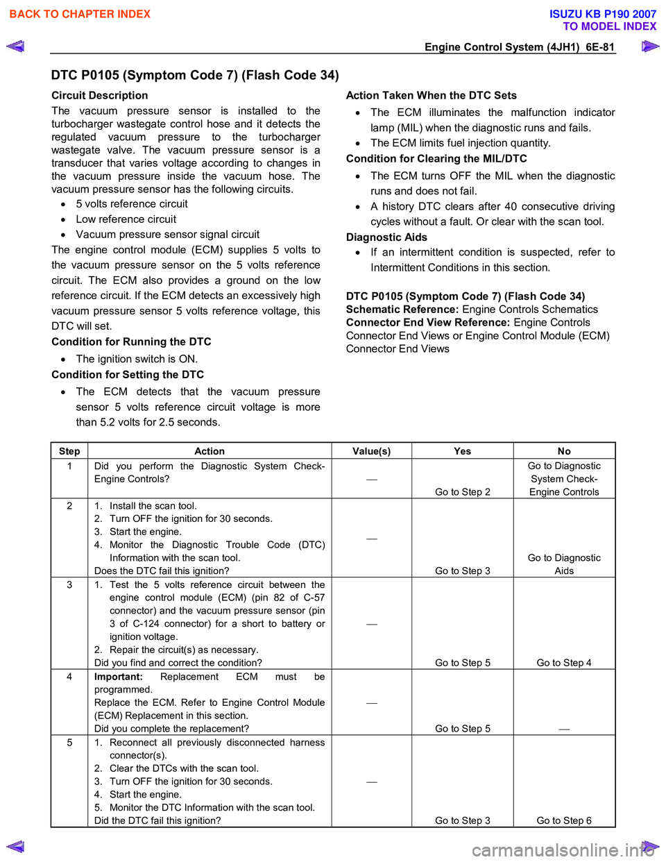
DTC P0105 (Symptom Code 7) (Flash Code 34)
Circuit Description
The vacuum pressure sensor is installed to the
turbocharger wastegate control hose and it detects the
regulated vacuum pressure to the turbocharge
r
wastegate valve. The vacuum pressure sensor is a
transducer that varies voltage according to changes in
the vacuum pressure inside the vacuum hose. The
vacuum pressure sensor has the following circuits.
• 5 volts reference circuit
• Low reference circuit
• Vacuum pressure sensor signal circuit
The engine control module (ECM) supplies 5 volts to
the vacuum pressure sensor on the 5 volts reference
circuit. The ECM also provides a ground on the lo
w
reference circuit. If the ECM detects an excessively high
vacuum pressure sensor 5 volts reference voltage, this
DTC will set.
Condition for Running the DTC
• The ignition switch is ON.
Condition for Setting the DTC
• The ECM detects that the vacuum pressure
sensor 5 volts reference circuit voltage is more
than 5.2 volts for 2.5 seconds.
Action Taken When the DTC Sets
• The ECM illuminates the malfunction indicato
r
lamp (MIL) when the diagnostic runs and fails.
• The ECM limits fuel injection quantity.
Condition for Clearing the MIL/DTC
• The ECM turns OFF the MIL when the diagnostic
runs and does not fail.
• A history DTC clears after 40 consecutive driving
cycles without a fault. Or clear with the scan tool.
Diagnostic Aids
• If an intermittent condition is suspected, refer to
Intermittent Conditions in this section.
DTC P0105 (Symptom Code 7) (Flash Code 34)
Schematic Reference: Engine Controls Schematics
Connector End View Reference: Engine Controls
Connector End Views or Engine Control Module (ECM)
Connector End Views
Step Action Value(s) Yes No
1 Did you perform the Diagnostic System Check-
Engine Controls?
Go to Step 2 Go to Diagnostic
System Check-
Engine Controls
2 1. Install the scan tool. 2. Turn OFF the ignition for 30 seconds.
3. Start the engine.
4. Monitor the Diagnostic Trouble Code (DTC) Information with the scan tool.
Does the DTC fail this ignition?
Go to Step 3 Go to Diagnostic
Aids
3 1. Test the 5 volts reference circuit between the engine control module (ECM) (pin 82 of C-57
connector) and the vacuum pressure sensor (pin
3 of C-124 connector) for a short to battery or
ignition voltage.
2. Repair the circuit(s) as necessary.
Did you find and correct the condition?
Go to Step 5 Go to Step 4
4 Important: Replacement ECM must be
programmed.
Replace the ECM. Refer to Engine Control Module
(ECM) Replacement in this section.
Did you complete the replacement?
Go to Step 5
5 1. Reconnect all previously disconnected harness
connector(s).
2. Clear the DTCs with the scan tool.
3. Turn OFF the ignition for 30 seconds.
4. Start the engine.
5. Monitor the DTC Information with the scan tool.
Did the DTC fail this ignition?
Go to Step 3 Go to Step 6
BACK TO CHAPTER INDEX
TO MODEL INDEX
ISUZU KB P190 2007
Page 1117 of 6020
Engine Control System (4JH1) 6E-83
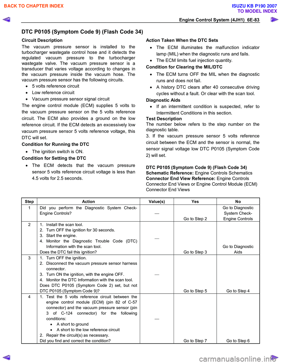
DTC P0105 (Symptom Code 9) (Flash Code 34)
Circuit Description
The vacuum pressure sensor is installed to the
turbocharger wastegate control hose and it detects the
regulated vacuum pressure to the turbocharge
r
wastegate valve. The vacuum pressure sensor is a
transducer that varies voltage according to changes in
the vacuum pressure inside the vacuum hose. The
vacuum pressure sensor has the following circuits.
• 5 volts reference circuit
• Low reference circuit
• Vacuum pressure sensor signal circuit
The engine control module (ECM) supplies 5 volts to
the vacuum pressure sensor on the 5 volts reference
circuit. The ECM also provides a ground on the lo
w
reference circuit. If the ECM detects an excessively low
vacuum pressure sensor 5 volts reference voltage, this
DTC will set.
Condition for Running the DTC
• The ignition switch is ON.
Condition for Setting the DTC
• The ECM detects that the vacuum pressure
sensor 5 volts reference circuit voltage is less than
4.5 volts for 2.5 seconds.
Action Taken When the DTC Sets
• The ECM illuminates the malfunction indicato
r
lamp (MIL) when the diagnostic runs and fails.
• The ECM limits fuel injection quantity.
Condition for Clearing the MIL/DTC
• The ECM turns OFF the MIL when the diagnostic
runs and does not fail.
• A history DTC clears after 40 consecutive driving
cycles without a fault. Or clear with the scan tool.
Diagnostic Aids
• If an intermittent condition is suspected, refer to
Intermittent Conditions in this section.
Test Description
The number below refers to the step number on the
diagnostic table.
3. If the vacuum pressure sensor 5 volts reference
circuit between the ECM and the sensor is normal, the
sensor signal voltage low DTC P0105 (Symptom Code
2) will set.
DTC P0105 (Symptom Code 9) (Flash Code 34)
Schematic Reference: Engine Controls Schematics
Connector End View Reference: Engine Controls
Connector End Views or Engine Control Module (ECM)
Connector End Views
Step Action Value(s) Yes No
1 Did you perform the Diagnostic System Check-
Engine Controls?
Go to Step 2 Go to Diagnostic
System Check-
Engine Controls
2 1. Install the scan tool. 2. Turn OFF the ignition for 30 seconds.
3. Start the engine.
4. Monitor the Diagnostic Trouble Code (DTC) Information with the scan tool.
Does the DTC fail this ignition?
Go to Step 3 Go to Diagnostic
Aids
3 1. Turn OFF the ignition. 2. Disconnect the vacuum pressure sensor harness connector.
3. Turn ON the ignition, with the engine OFF.
4. Monitor the DTC Information with the scan tool.
Does DTC P0105 (Symptom Code 2) set, but not
DTC P0105 (Symptom Code 9)?
Go to Step 5 Go to Step 4
4 1. Test the 5 volts reference circuit between the engine control module (ECM) (pin 82 of C-57
connector) and the vacuum pressure sensor (pin
3 of C-124 connector) for the following
conditions: • A short to ground
• A short to the low reference circuit
2. Repair the circuit(s) as necessary.
Did you find and correct the condition?
Go to Step 7 Go to Step 6
BACK TO CHAPTER INDEX
TO MODEL INDEX
ISUZU KB P190 2007
Page 1137 of 6020
Engine Control System (4JH1) 6E-103
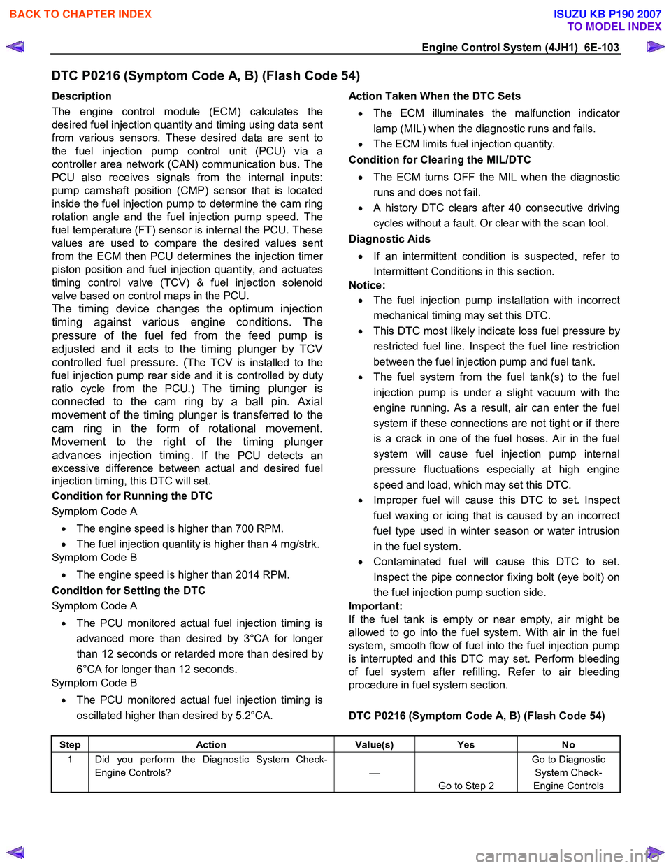
DTC P0216 (Symptom Code A, B) (Flash Code 54)
Description
The engine control module (ECM) calculates the
desired fuel injection quantity and timing using data sent
from various sensors. These desired data are sent to
the fuel injection pump control unit (PCU) via a
controller area network (CAN) communication bus. The
PCU also receives signals from the internal inputs:
pump camshaft position (CMP) sensor that is located
inside the fuel injection pump to determine the cam ring
rotation angle and the fuel injection pump speed. The
fuel temperature (FT) sensor is internal the PCU. These
values are used to compare the desired values sent
from the ECM then PCU determines the injection time
r
piston position and fuel injection quantity, and actuates
timing control valve (TCV) & fuel injection solenoid
valve based on control maps in the PCU.
The timing device changes the optimum injection
timing against various engine conditions. The
pressure of the fuel fed from the feed pump is
adjusted and it acts to the timing plunger by TCV
controlled fuel pressure. (
The TCV is installed to the
fuel injection pump rear side and it is controlled by dut
y
ratio cycle from the PCU.) The timing plunger is
connected to the cam ring by a ball pin. Axial
movement of the timing plunger is transferred to the
cam ring in the form of rotational movement.
Movement to the right of the timing plunge
r
advances injection timing.
If the PCU detects an
excessive difference between actual and desired fuel
injection timing, this DTC will set.
Condition for Running the DTC
Symptom Code A
• The engine speed is higher than 700 RPM.
• The fuel injection quantity is higher than 4 mg/strk.
Symptom Code B
• The engine speed is higher than 2014 RPM.
Condition for Setting the DTC
Symptom Code A
• The PCU monitored actual fuel injection timing is
advanced more than desired by 3°CA for longe
r
than 12 seconds or retarded more than desired by
6°CA for longer than 12 seconds.
Symptom Code B
• The PCU monitored actual fuel injection timing is
oscillated higher than desired by 5.2°CA.
Action Taken When the DTC Sets
• The ECM illuminates the malfunction indicato
r
lamp (MIL) when the diagnostic runs and fails.
• The ECM limits fuel injection quantity.
Condition for Clearing the MIL/DTC
• The ECM turns OFF the MIL when the diagnostic
runs and does not fail.
• A history DTC clears after 40 consecutive driving
cycles without a fault. Or clear with the scan tool.
Diagnostic Aids
• If an intermittent condition is suspected, refer to
Intermittent Conditions in this section.
Notice:
• The fuel injection pump installation with incorrect
mechanical timing may set this DTC.
• This DTC most likely indicate loss fuel pressure by
restricted fuel line. Inspect the fuel line restriction
between the fuel injection pump and fuel tank.
• The fuel system from the fuel tank(s) to the fuel
injection pump is under a slight vacuum with the
engine running. As a result, air can enter the fuel
system if these connections are not tight or if there
is a crack in one of the fuel hoses. Air in the fuel
system will cause fuel injection pump internal
pressure fluctuations especially at high engine
speed and load, which may set this DTC.
• Improper fuel will cause this DTC to set. Inspect
fuel waxing or icing that is caused by an incorrect
fuel type used in winter season or water intrusion
in the fuel system.
• Contaminated fuel will cause this DTC to set.
Inspect the pipe connector fixing bolt (eye bolt) on
the fuel injection pump suction side.
Important:
If the fuel tank is empty or near empty, air might be
allowed to go into the fuel system. W ith air in the fuel
system, smooth flow of fuel into the fuel injection pump
is interrupted and this DTC may set. Perform bleeding
of fuel system after refilling. Refer to air bleeding
procedure in fuel system section.
DTC P0216 (Symptom Code A, B) (Flash Code 54)
Step Action Value(s) Yes No
1 Did you perform the Diagnostic System Check-
Engine Controls?
Go to Step 2 Go to Diagnostic
System Check-
Engine Controls
BACK TO CHAPTER INDEX
TO MODEL INDEX
ISUZU KB P190 2007
Page 1138 of 6020
6E-104 Engine Control System (4JH1)
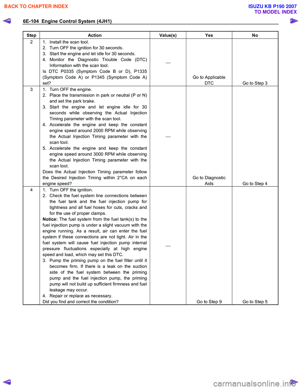
Step Action Value(s) Yes No
2 1. Install the scan tool.
2. Turn OFF the ignition for 30 seconds.
3. Start the engine and let idle for 30 seconds.
4. Monitor the Diagnostic Trouble Code (DTC) Information with the scan tool.
Is DTC P0335 (Symptom Code B or D), P1335
(Symptom Code A) or P1345 (Symptom Code A)
set?
Go to Applicable DTC Go to Step 3
3 1. Turn OFF the engine. 2. Place the transmission in park or neutral (P or N) and set the park brake.
3. Start the engine and let engine idle for 30 seconds while observing the Actual Injection
Timing parameter with the scan tool.
4. Accelerate the engine and keep the constant engine speed around 2000 RPM while observing
the Actual Injection Timing parameter with the
scan tool.
5. Accelerate the engine and keep the constant engine speed around 3000 RPM while observing
the Actual Injection Timing parameter with the
scan tool.
Does the Actual Injection Timing parameter follow
the Desired Injection Timing within 2°CA on each
engine speed?
Go to Diagnostic Aids Go to Step 4
4 1. Turn OFF the ignition. 2. Check the fuel system line connections between the fuel tank and the fuel injection pump for
tightness and all fuel hoses for cuts, cracks and
for the use of proper clamps.
Notice: The fuel system from the fuel tank(s) to the
fuel injection pump is under a slight vacuum with the
engine running. As a result, air can enter the fuel
system if these connections are not tight. Air in the
fuel system will cause fuel injection pump internal
pressure fluctuations especially at high engine
speed and load, which may set this DTC.
3. Pump the priming pump on the fuel filter until it becomes firm. If there is a leak on the suction
side of the fuel system between the priming
pump and the fuel injection pump, the priming
pump will not build up sufficient firmness and fuel
leakage may occur.
4. Repair or replace as necessary.
Did you find and correct the condition?
Go to Step 9 Go to Step 5
BACK TO CHAPTER INDEX
TO MODEL INDEX
ISUZU KB P190 2007