Page 1500 of 6020

6A-140 ENGINE MECHANICAL (4JK1/4JJ1)
Lubrication System
Service Precautions
• During each disassembly, remove the old gasket
adhering to each part and mating part completel
y
using a scraper at the location, where the fluid
gasket is to be used, clean the traces of oil,
moisture, and dirt completely using waste cotton
and apply the specified new fluid gasket at each
location.
•
Avoid excessive or insufficient coating volume.
Note that seizure may occur in case of excessive
coating due to clogging of the oil gallery and oil jet,
and oil and water leakage may occur if the coating
is insufficient.
• Always, the start and end of the application should
be overlapped.
Explanations on functions and operation
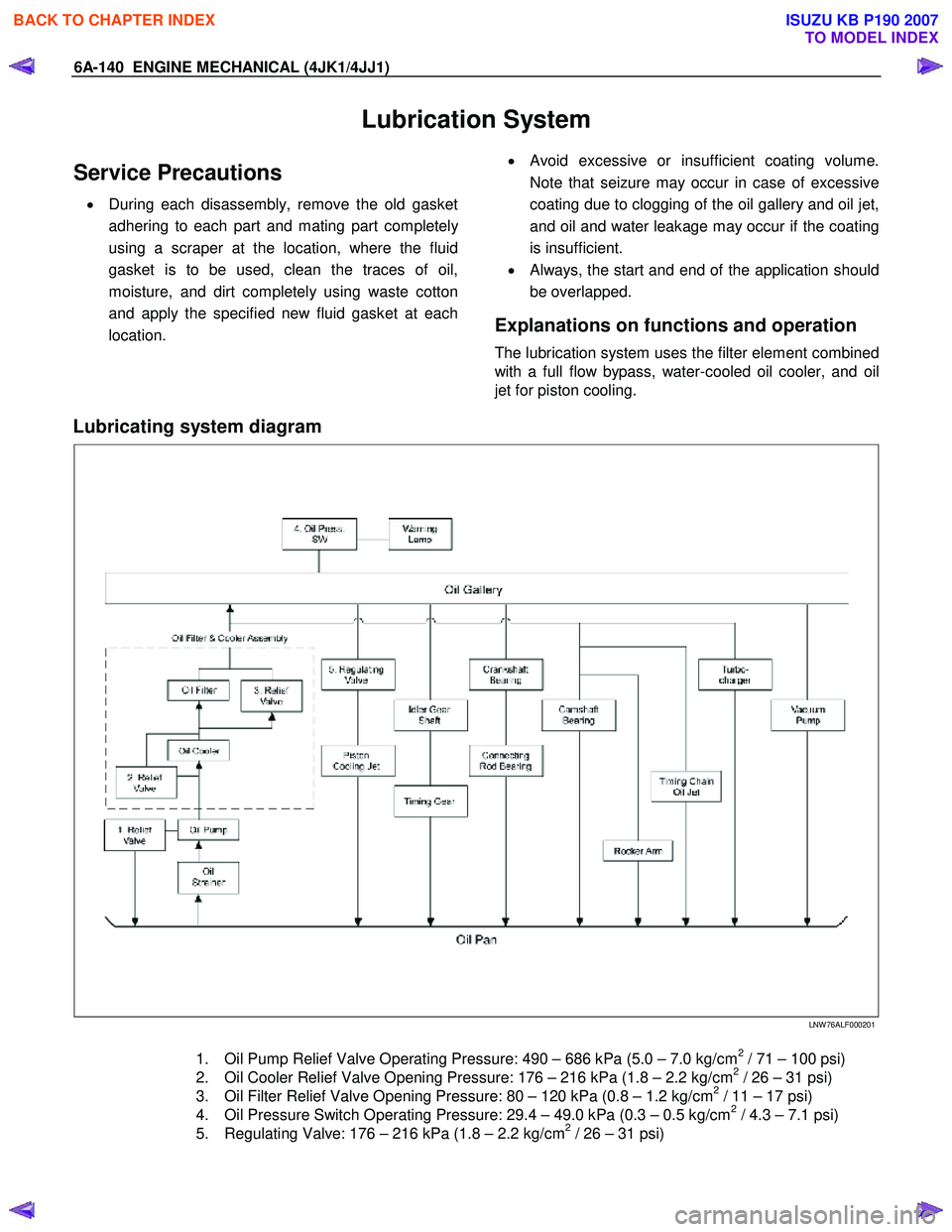
The lubrication system uses the filter element combined
with a full flow bypass, water-cooled oil cooler, and oil
jet for piston cooling.
Lubricating system diagram
LNW 76ALF000201
1. Oil Pump Relief Valve Operating Pressure: 490 – 686 kPa (5.0 – 7.0 kg/cm2 / 71 – 100 psi)
2. Oil Cooler Relief Valve Opening Pressure: 176 – 216 kPa (1.8 – 2.2 kg/cm2 / 26 – 31 psi)
3. Oil Filter Relief Valve Opening Pressure: 80 – 120 kPa (0.8 – 1.2 kg/cm2 / 11 – 17 psi)
4. Oil Pressure Switch Operating Pressure: 29.4 – 49.0 kPa (0.3 – 0.5 kg/cm2 / 4.3 – 7.1 psi)
5. Regulating Valve: 176 – 216 kPa (1.8 – 2.2 kg/cm2 / 26 – 31 psi)
BACK TO CHAPTER INDEX
TO MODEL INDEX
ISUZU KB P190 2007
Page 1501 of 6020

ENGINE MECHANICAL (4JK1/4JJ1) 6A-141
Functional Check
Oil pressure check
1. Check whether the engine oil is contaminated with
dirt, light oil, or water. If contaminated with dirt,
light oil, or water (after examining the cause and
taking the appropriate measures for light oil o
r
water contamination), replace the oil.
2. Check the engine oil level. The oil level should be between the two holes of the level gauge. If the oil
level is insufficient, replenish it.
3. Remove the oil pressure switch on the nipple.
4. Install the oil pressure gauge on the nipple.
RTW 56ASH015501
Legend
1. Oil Pressure Switch
5. W arm the engine.
6. Measure the oil pressure, to check whether it is more than 400 kPa (4 kg/cm
2 / 58 psi) at 3600
rpm.
7. Stop the engine.
8. Remove the oil pressure gauge.
9. Install the oil pressure switch.
10. Start the engine and check for oil leakage.
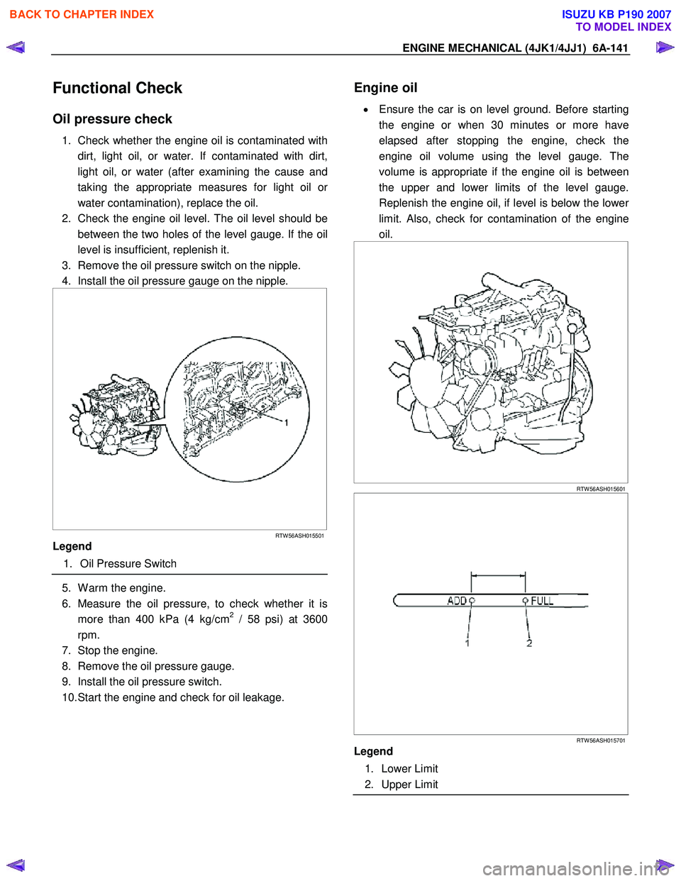
Engine oil
•
Ensure the car is on level ground. Before starting
the engine or when 30 minutes or more have
elapsed after stopping the engine, check the
engine oil volume using the level gauge. The
volume is appropriate if the engine oil is between
the upper and lower limits of the level gauge.
Replenish the engine oil, if level is below the lowe
r
limit. Also, check for contamination of the engine
oil.
RTW 56ASH015601
RTW 56ASH015701
Legend
1. Lower Limit
2. Upper Limit
BACK TO CHAPTER INDEX
TO MODEL INDEX
ISUZU KB P190 2007
Page 1502 of 6020
6A-142 ENGINE MECHANICAL (4JK1/4JJ1)
Engine oil leakage
• In the lift up condition, confirm that there are no
leaks from the cylinder head cover and oil pan.
BACK TO CHAPTER INDEX
TO MODEL INDEX
ISUZU KB P190 2007
Page 1503 of 6020
ENGINE MECHANICAL (4JK1/4JJ1) 6A-143
Oil Filter Cartridge
Components
RTW 56ASF000101
Legend 1. Oil Filter Cartridge
Removal
1. Place a tray under the oil filter cartridge.
2. Remove the oil filter cartridge using the oil filte
r
wrench.
Special tool
Oil filter wrench: 5-8840-0203-0 (1)
RTW 56ASH012501
Installation
1. Install the oil filter cartridge.
•
Apply grease or engine oil to the seal in the
cartridge and install it using the oil filter wrench.
• Tighten the cartridge using the specified torque.
Tightening torque: 20 N·m (2.0 kg·m / 14 lb ft) Or
After it comes in contact with the oil seal,
tighten it through an additional turn of 1 and
1/4.
Special tool
Oil filter wrench: 5-8840-0203-0
BACK TO CHAPTER INDEX
TO MODEL INDEX
ISUZU KB P190 2007
Page 1504 of 6020
6A-144 ENGINE MECHANICAL (4JK1/4JJ1)
Special Tools
ILLUSTRATION PART NO.
PART NAME
5-8840-0203-0
Oil filter wrench
BACK TO CHAPTER INDEX
TO MODEL INDEX
ISUZU KB P190 2007
Page 1505 of 6020
ENGINE MECHANICAL (4JK1/4JJ1) 6A-145
Oil Filter Assembly and Oil Cooler
Components
RTW 56AMF000401
Legend
1. Exhaust Manifold
2. Generator Bracket
3. Generator Adjustment Bracket 4. W ater Bypass Pipe
5. W ater Intake Pipe
6. Oil Filter Assembly and Oil Cooler
Removal
1. Remove the exhaust manifold.
Refer to removal procedure for "Turbocharger and Exhaust Manifold" in this manual.
2. Remove the generator.
Refer to removal procedure for generator in this manual.
3. Remove the adjustment bracket of generator.
4. Remove the bracket of generator.
5. Remove the water bypass pipe (1).
RTW 56ASH008401
BACK TO CHAPTER INDEX
TO MODEL INDEX
ISUZU KB P190 2007
Page 1506 of 6020
6A-146 ENGINE MECHANICAL (4JK1/4JJ1)
6. Remove the water intake pipe.
RTW 56ASH012601
Legend
1. W ater Intake Pipe
2. Bracket
3. Bracket
4. Bolt
7. Remove the oil cooler.
RTW 66ASH009101
Disassembly
1. Remove the element mounting nut (1).
RTW 56ASH012901
2. Remove the element (1).
3. Remove the gasket (2).
RTW 56ASH013001
BACK TO CHAPTER INDEX
TO MODEL INDEX
ISUZU KB P190 2007
Page 1507 of 6020
ENGINE MECHANICAL (4JK1/4JJ1) 6A-147
Reassembly
1. Install the gasket on the element.
2. Install the element.
3. Tighten the element fixing nut using the specified torque.
Tightening torque: 25 N ⋅
⋅⋅
⋅
m (2.5 kg ⋅
⋅⋅
⋅
m / 18 lb ft)
Installation
1. Install the oil filter and cooler.
• Install the O-ring on the oil filter and cooler,
apply grease.
•
Apply the liquid gasket and mount within 5
minutes. Apply liquid gasket (ThreeBond TB-
1207C or equivalent) to the flange surface
groove (cylinder block). Bead diameter must
be between 2 and 3 mm (0.079 and 0.118 in).
Refer to the illustration for the offset position
(no more than 1 mm (0.004 in)).
RTW 56ASH013101
Legend
1. Liquid Gasket
2. O-ring
• Align the oil filter and cooler holes with the
cylinder block studs. Install the oil cooler to the
cylinder clock.
BACK TO CHAPTER INDEX
TO MODEL INDEX
ISUZU KB P190 2007